Microsemi SmartFusion2 Quick Start Manual
Dmpm kit
Hide thumbs
Also See for SmartFusion2:
- User manual (829 pages) ,
- Demo manual (40 pages) ,
- Configuration manual (23 pages)
Advertisement
Quick Links
SmartFusion2 DMPM Kit
Quickstart Guide
Overview
Microsemi's SmartFusion
SmartFusion DMPM kit by utilizing SmartFusion2 FPGA's ability to manage up to 64 channels of both analog and
digital point-of-loads. The SF2-DMPM Daughter Board provides a bench top demonstration and development platform
for Microsemi's SmartFusion2 MPM reference design, which incorporates eight digital regulators (controlled and
monitored through the PMBus) in addition to eight Microsemi analog regulators, which are monitored through an
external ADC. It includes a PMBus header for I
module. The SF2-DMPM-KIT connects to the SF2-DEV-KIT through the FMC header.
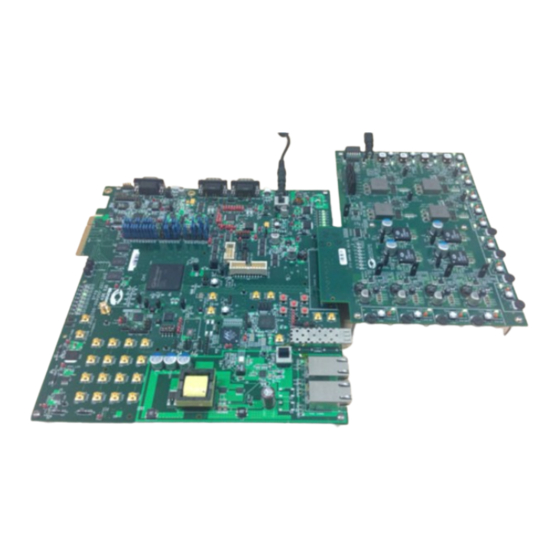
Figure 1 • SF2 DMPM Daughter Board to SF2 Development Kit Through Their Respective FMC Connectors
September 2013
© 2013 Microsemi Corporation
®
2 Digital Mixed-Signal Power Management Daughter Card Kit builds on the
2
C communication, which can be evaluated using the included USB-I
2
C
1
Advertisement

Related Manuals for Microsemi SmartFusion2


Summary of Contents for Microsemi SmartFusion2
- Page 1 2 Digital Mixed-Signal Power Management Daughter Card Kit builds on the SmartFusion DMPM kit by utilizing SmartFusion2 FPGA’s ability to manage up to 64 channels of both analog and digital point-of-loads. The SF2-DMPM Daughter Board provides a bench top demonstration and development platform for Microsemi’s SmartFusion2 MPM reference design, which incorporates eight digital regulators (controlled and...
- Page 2 12 V, 6 A AC Power Adapter FlashPro4 Programmer USB A to MicroB Cable USB MicroA to A Cable USB A to Mini-B Cable PCI Edge Card Ribbon Cable Figure 2 • SF2-DMPM Daughter Board with the SmartFusion2 Development Kit Board...
-
Page 3: Installation
Run the installer and follow the installation wizard instructions. By default, the MPM installs into the C:\Microsemi\SF2_MPM_RefDesign_v6.1 folder and this is the recommended location for it. In particular, avoid installing it in a folder that is very deeply nested or has a very long path name. Otherwise, some tools may encounter problems accessing files with names longer than 259 characters*. - Page 4 SmartFusion2 Development Kit Setup The following jumper settings are required on the SmartFusion2 Dev-Kit to route the signals required for the DMPM board to the FMC connector. Due to the number of jumpers needed, we have provided pictures of the jumpers as well as the list of pins.
- Page 5 SmartFusion2 Development Kit Setup Table 3 • List of Jumpers Needed on the SF2-DEV-KIT J174 pins 2 and 3 jumpered J172 pins 2 and 3 jumpered J184 pins 2 and 3 jumpered J175 pins 2 and 3 jumpered J179 pins 2 and 3 jumpered...
- Page 6 Using the MPM Figure 5 • SF2-DMPM-DB l C Jumpers JP23 should have pins 1 and 2 jumpered and J24 should be jumpered to provide 3.3 V and 2.5 V supplies to the SF2- DMPM-DB board from the FMC connector. J22 should have 7 x 3 jumpers installed as shown in Figure 5 above, to link the eight DPOLs to PMBUS1.
- Page 7 Reset the SmartFusion2 Development board by pressing SW9 RESET Note: The power up order is important and it is advised to reset the system using SW9 on the SmartFusion2 Development Kit after powering up. *See the Microsoft MSDN article for more on path length...
- Page 8 Using the MPM The MPM Reference Design Demo Without the MPM GUI Once the MPM reference design has been programmed to the target hardware, the demo can be viewed even without the MPM GUI by using SW3 on the Dev-Kit to initiate power-up and power-down sequences and observing the current state of the MPM on the Dev-Kit LEDs.
- Page 9 Table 4 • MPM Status Description Status Description Stopped Power-off sequencing is successful and the MPM is idle. None of the following are active: channel threshold monitoring, output flag generation, and open or closed trimming. The channel voltages can be read in any state.
- Page 10 Using the MPM If you press SW3 to initiate power-up sequencing, the MPM state changes to Starting and you can see the various regulator enabled LEDs on the SF2-DMPM-DB turning on in sequence. If the status does not change to Started and the power-on sequence restarts, you can adjust the voltage of the individual APOL channels via the associated potentiometers to complete the sequencing.
- Page 11 Use the included standard USB A/B cable to connect the USB-ISS to your PC. Install the drivers that are bundled with the MPM GUI in the C:\Microsemi\SF2_MPM_RefDesign_v6.1\Devantech_USB-ISS_drivers folder. After installing the drivers, and plugging the USB-ISS module into a spare USB port, find which COM port it has been assigned to.
- Page 12 Using the MPM If you want to change the COM port number—just right click on it, select properties > advanced > Port Settings > COMport number from the available list. The COM port default settings are sufficient. Figure 13 • Device Manager...
- Page 13 Running the Demo Design With the MPM GUI Note the COM port assigned to the USB-ISS communications module. Run the MPM GUI, select Data > PC > TestI2C Dongle. Select the USB-ISS COM port from the Communications > Port drop-down list. Select Test Dongle from the Activity >...
- Page 14 Using the MPM The default I C slave address for the MPM is 100 (decimal). All menu options under Data > I2C launch the MPM I2C Communications dialog with different default settings. Refer to Figure 15 for an example: Data > I2C > Monitor Values ON/OFF.
-
Page 15: Documentation Resources
® The SmartFusion2 Development Kit is supported by Libero System-on-Chip (SoC) software v11.0 and later. SoftConsole software IDE and FlashPro software tools can be used for software design and debug. SmartFusion2 is also supported by ® Keil™ and IAR Systems software, which can be installed separately. Refer to the SmartFusion2 Development Kit User’s... - Page 16 Microsemi Corporate Headquarters One Enterprise, Aliso Viejo CA 92656 USA © 2013 Microsemi Corporation. All rights reserved. Microsemi and the Microsemi logo are trademarks of Within the USA: +1 (949) 380-6100 Microsemi Corporation. All other trademarks and service marks are the property of their respective owners.
Need help?
Do you have a question about the SmartFusion2 and is the answer not in the manual?
Questions and answers