MIR MiR250 User Manual
Hide thumbs
Also See for MiR250:
- User manual (249 pages) ,
- Manual (195 pages) ,
- Installer/integrator manual (170 pages)
Table of Contents
Advertisement
Advertisement
Table of Contents

Related Manuals for MIR MiR250


Summary of Contents for MIR MiR250
- Page 1 MiR250 User Guide Date: 09/2023 Version: 2.1 (en) Robot hardware version: 2.1...
-
Page 2: Copyright And Disclaimer
Copyright and disclaimer Copyright and disclaimer Mobile Industrial Robots A/S (MiR) makes no warranties, expressed or implied, in respect of this document or its contents. In addition, the contents of this document are subject to change without prior notice. Every precaution has been taken in the preparation of this document. -
Page 3: Table Of Contents
4. Getting started 4.1 In the box 4.2 Unpacking MiR250 5. Usage 5.1 Powering up the robot 5.2 Shutting down the robot 5.3 Connecting to the robot interface MiR250 User Guide (en) 09/2023 - v.2.1 ©Copyright 2020–2023: Mobile Industrial Robots A/S. - Page 4 9.2 Maintenance tasks for operators 10. Storage 10.1 Preparing the robot for storage 10.2 Storage time 11. Battery and charging 11.1 Connecting the battery 11.2 Disconnecting the battery MiR250 User Guide (en) 09/2023 - v.2.1 ©Copyright 2020–2023: Mobile Industrial Robots A/S.
- Page 5 17.2 Packing the robot for transportation 17.3 Transporting the battery 18. Disposal 19. Payload distribution 19.1 Side view 19.2 Front view 19.3 Top view 20. Declaration of conformity example 21. Glossary MiR250 User Guide (en) 09/2023 - v.2.1 ©Copyright 2020–2023: Mobile Industrial Robots A/S.
-
Page 6: About This Document
1. About this document 1. About this document This user guide explains how to set up and start operating your MiR250 robot. This guide also contains information regarding the external and internal components of MiR250 along with instructions for proper maintenance of the robot. You will also find information regarding safety and specifications needed to commission a safe MiR250 robot application. - Page 7 Best practice guides provide helpful information you can use when commissioning or operating your robot. REST API references for MiR robots, MiR hooks, and MiR Fleet. HTTP requests can be used to control robots, hooks, and MiR Fleet. MiR Network and Wi-Fi guide specifies the performance requirements of your network and how you must configure it for MiR robots and MiR Fleet to operate successfully.
-
Page 8: Version History
1. About this document Resources MiR Log Analytics and MiR Insights are tools you can use to analyze how well your robots or fleet are performing. MiR Log Analytics is a free tool that lets you analyze recorded performance from error logs, and MiR Insights requires a paid license, but runs continuously alongside MiR Fleet to give real-time data on several metrics. - Page 9 Added warning to ensure all personnel wear safety shoes. Affects section: General safety precautions. Added warning regarding clearing missions and re-added section Error handling section. Affects section: Error handling MiR250 User Guide (en) 09/2023 - v.2.1 ©Copyright 2020–2023: Mobile Industrial Robots A/S.
- Page 10 Added sections: Specifications and Space requirements. Changed structure and order of content Updated copyright. Updated reference to robot or MiR Fleet reference guide to interface guide. MiR250 User Guide (en) 09/2023 - v.2.1 ©Copyright 2020–2023: Mobile Industrial Robots A/S. Updated style.
- Page 11 Added information about laser scanner range. Affects section: Obstacle detection. Added information about camera vertical angle. Affects section: Obstacle detection. Added information about wheel wear down tolerance. Affects section: Maintenance. General improvements throughout the manual. MiR250 User Guide (en) 09/2023 - v.2.1 ©Copyright 2020–2023: Mobile Industrial Robots A/S.
- Page 12 Robot HW: 1.0 Updated section: Operating hazard zones. General improvements throughout the manual. Date: 2020-07-01 Robot HW: 1.0 General improvements throughout the manual. Date: 2020-06-26 Robot HW: 1.0 First edition MiR250 User Guide (en) 09/2023 - v.2.1 ©Copyright 2020–2023: Mobile Industrial Robots A/S.
-
Page 13: Product Presentation
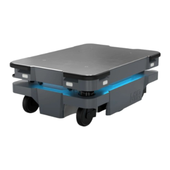
2. Product presentation 2. Product presentation MiR250 is an autonomous mobile robot that can transport loads up to 250 kg indoors within production facilities, warehouses, and other industrial locations where access to the public is restricted. Users operate MiR250 via a web-based user interface—see "Connecting to the robot interface"... -
Page 14: Specifications
If used with custom modules, all obligations of a manufacturer apply to the individual who performs the modifications. All modifications must be in accordance with the machinery directive. MiR250 is designed for and all risks are considered when used with one of the following types of top modules: MiR Shelf Carrier 250 to transport MiR supported shelves... - Page 15 We recommend either avoiding these materials, covering them with opaque and matte material the robot can detect, or ensuring the robot does not operate in areas with these materials. MiR250 User Guide (en) 09/2023 - v.2.1 ©Copyright 2020–2023: Mobile Industrial Robots A/S.
-
Page 16: Required Space
You can find the guide and calculator on Support Portal. Figure 2.1 The required space when the robot drives straight Figure 2.2 The required space when the robot takes a 90° turn MiR250 User Guide (en) 09/2023 - v.2.1 ©Copyright 2020–2023: Mobile Industrial Robots A/S. - Page 17 Figure 2.3 The required space when the robot drives through a doorway Figure 2.4 The required space when two robots pass each other Figure 2.5 The required space when the robot pivots MiR250 User Guide (en) 09/2023 - v.2.1 ©Copyright 2020–2023: Mobile Industrial Robots A/S.
-
Page 18: Compatible Products
MiR Charge 48V enable MiR robots to recharge their batteries. Together with MiR Fleet, charging of robots can be fully automated, ensuring that robots never run out of power during missions. MiR250 User Guide (en) 09/2023 - v.2.1 ©Copyright 2020–2023: Mobile Industrial Robots A/S. -
Page 19: External Parts
"Light indicators and speaker" on page 58 3D depth camera: two pcs., Caster wheel with foot guard: both in the front four pcs., one in each corner MiR250 User Guide (en) 09/2023 - v.2.1 ©Copyright 2020–2023: Mobile Industrial Robots A/S. -
Page 20: Internal Parts
Right top compartment—see "Top compartments" on page 24 2.6 Internal parts Most internal parts of MiR250 are accessed through covers that open to different compartments—see "Accessing the internal parts" on page 97. CAUTION Removing covers from the robot exposes parts connected to the power supply, which can result in a short circuit that will damage the robot and could injure personnel. - Page 21 Table 2.2 Identification of internal parts in Figure 2.7 Pos. Description Pos. Description Robot computer Motor controller carrier board Loudspeaker Charging pads under robot and broom 3D cameras MiR250 User Guide (en) 09/2023 - v.2.1 ©Copyright 2020–2023: Mobile Industrial Robots A/S.
- Page 22 Table 2.3 Identification of internal parts in Figure 2.8 Pos. Description Pos. Description Battery Battery connector Battery lever Cable charging interface Ethernet port Battery lever lock Safety PLC Power board Identification label MiR250 User Guide (en) 09/2023 - v.2.1 ©Copyright 2020–2023: Mobile Industrial Robots A/S.
- Page 23 Table 2.4 Identification of internal parts in Figure 2.9 Pos. Description Pos. Description Safe Stop 1 (SS1) contactor Safe Torque Off (STO) contactor Safe Torque Off (STO) contactor Bogie and drivetrain MiR250 User Guide (en) 09/2023 - v.2.1 ©Copyright 2020–2023: Mobile Industrial Robots A/S.
- Page 24 Figure 2.10 Pos. Description Pos. Description Switch Safe Stop 1 (SS1) contactor Bogie and drivetrain Top compartments For more information on electrical interfaces, see "Electrical interfaces" on page 144. MiR250 User Guide (en) 09/2023 - v.2.1 ©Copyright 2020–2023: Mobile Industrial Robots A/S.
-
Page 25: System Overview
The lines between components indicate a significant connection either for communication or power. For more detailed schematics, see the wiring diagram for MiR250 on MiR Support Portal. MiR250 User Guide (en) 09/2023 - v.2.1 ©Copyright 2020–2023: Mobile Industrial Robots A/S. -
Page 26: Warranty
2. Product presentation Figure 2.12 Overview of the internal components and how they are connected in MiR250 2.8 Warranty Mobile Industrial Robots offers a standard warranty on all products. Contact your distributor to see the terms and extent of product coverage. -
Page 27: Safety
Pay particular attention to the safety instructions and warnings. NOTICE Mobile Industrial Robots disclaims any and all liability if MiR250 or its accessories are damaged, changed, or modified in any way. Mobile Industrial Robots cannot be held responsible for any damages caused to MiR250, accessories, or any other equipment due to programming errors or malfunctioning of MiR250. -
Page 28: General Safety Precautions
All personnel must be informed of the side Protective fields of the robot and be instructed to wear safety shoes near an operating robot—see "Field switching and Personnel detection" on page 74. MiR250 User Guide (en) 09/2023 - v.2.1 ©Copyright 2020–2023: Mobile Industrial Robots A/S. - Page 29 This equipment is not intended for use in residential environments and may not provide adequate protection to radio reception in such environments. Do not use the robot in residential environments. MiR250 User Guide (en) 09/2023 - v.2.1 ©Copyright 2020–2023: Mobile Industrial Robots A/S.
- Page 30 Emergency stop function in emergency situations. Ensure that all personnel are instructed to stay clear of operating hazard zones when the robot is in the zone. MiR250 User Guide (en) 09/2023 - v.2.1 ©Copyright 2020–2023: Mobile Industrial Robots A/S.
-
Page 31: Warning Label
3. Safety 3.3 Warning label MiR250 is supplied with a warning label that specifies that it is strictly prohibited to ride on the robot. The label must be placed on the robot or top module so that it is clearly visible. -
Page 32: Residual Risks
Using the robot together with an external radio module that in any way results in simultaneously active radio transmitters The following list gives examples of custom modules that are foreseeable misuse of MiR250: Top modules (including the payload) that increase the physical dimensions of MiR250... - Page 33 Other significant hazards may be present in a specific robot installation. Failure to identify hazards may result in injury to personnel or damage to equipment. Identify all hazards specific to your robot installation during commissioning. MiR250 User Guide (en) 09/2023 - v.2.1 ©Copyright 2020–2023: Mobile Industrial Robots A/S.
-
Page 34: Getting Started
4. Getting started 4. Getting started To get the robot started, see the guide MiR250 Quick Start delivered with the robot, or follow these steps: Unpack MiR250—see "Unpacking MiR250" on the next page. Connect the battery—see "Connecting the battery" on page 120. -
Page 35: Unpacking Mir250
This is necessary as the robot drives out of the box on a ramp. Cut the protective straps surrounding the box. MiR250 User Guide (en) 09/2023 - v.2.1 ©Copyright 2020–2023: Mobile Industrial Robots A/S. - Page 36 4. Getting started Remove the lid from the box. Take the box with the Emergency stop box, antennas, and printed documents out of the box. MiR250 User Guide (en) 09/2023 - v.2.1 ©Copyright 2020–2023: Mobile Industrial Robots A/S.
- Page 37 Place the lid of the box so that you can use it as a ramp. Align the lid so that it is flush with the base of the box. MiR250 User Guide (en) 09/2023 - v.2.1 ©Copyright 2020–2023: Mobile Industrial Robots A/S.
- Page 38 Use a T45 screwdriver to unscrew the mounting screw, and tighten it to 15 Nm when remounting it with the Emergency stop box. Screw on the two antennas, one on each top compartment. MiR250 User Guide (en) 09/2023 - v.2.1 ©Copyright 2020–2023: Mobile Industrial Robots A/S.
-
Page 39: Usage
5. Usage 5. Usage The following sections describe how the robot is operated and customized. MiR250 User Guide (en) 09/2023 - v.2.1 ©Copyright 2020–2023: Mobile Industrial Robots A/S. -
Page 40: Powering Up The Robot
When the initialization process ends, the robot goes into Protective stop. Press the Resume button to clear the Protective stop. The robot is now ready for operation. MiR250 User Guide (en) 09/2023 - v.2.1 ©Copyright 2020–2023: Mobile Industrial Robots A/S. -
Page 41: Shutting Down The Robot
5. Usage If you are not able to power up the robot upon delivery, see MiR 48V Battery Technical Guide to troubleshoot the issue. You can find this guide on MiR Support Portal. 5.2 Shutting down the robot To shut down MiR250, follow these steps: Ensure that the robot is not moving or executing an action. -
Page 42: Connecting To The Robot Interface
You can connect to the robot using an Ethernet cable or an access point. If you are located in North America, EU, or a part of EAC, you can purchase a MiR Access Point from MiR. Outside these areas, you need to use your own access point that is approved for use in your region. If you choose to use an access point, you must ensure that the robot is disconnected from the wireless network before attaching the access point to remain compliant—see... - Page 43 Locate the RJ45 Ethernet port in the rear compartment to the right of the battery fast- swap assembly. Connect your device directly to the robot using an Ethernet cable, or connect an access point to the Ethernet port for a wireless connection. MiR250 User Guide (en) 09/2023 - v.2.1 ©Copyright 2020–2023: Mobile Industrial Robots A/S.
-
Page 44: Connecting The Robot To A Wi-Fi Network
To comply with the robot's certification, you must use an Ethernet cable to avoid simultaneously active radio transmitters while setting up the connection to the local Wi-Fi network. MiR250 User Guide (en) 09/2023 - v.2.1 ©Copyright 2020–2023: Mobile Industrial Robots A/S. - Page 45 Select the network you want the robot to be connected to, and fill out the displayed fields—see the guide How to connect a MiR robot to a Wi-Fi network for more information about the Wi-Fi settings. You can find this guide on MiR Support Portal.
-
Page 46: Control Panel
To disconnect the robot from a Wi-Fi network, select Disconnect. 5.5 Control panel MiR250 has a control panel in the rear-left corner of the robot. Figure 5.1 The MiR250 control panel MiR250 User Guide (en) 09/2023 - v.2.1 ©Copyright 2020–2023: Mobile Industrial Robots A/S. - Page 47 Blinking blue: The robot is waiting for a user action. For example, press the button to clear a Protective stop or acknowledge the change of operating mode. Power button Pressing this button for three seconds turns the robot on or shuts it off. MiR250 User Guide (en) 09/2023 - v.2.1 ©Copyright 2020–2023: Mobile Industrial Robots A/S.
-
Page 48: Preventing Unauthorized Use
Keep passwords to connect to the robot interface and the robot components strictly confidential. Assign each robot user with their own user in the interface and make sure they each have a unique username and password. MiR250 User Guide (en) 09/2023 - v.2.1 ©Copyright 2020–2023: Mobile Industrial Robots A/S. -
Page 49: Operating The Robot
To control the robot manually, you must connect to the robot interface—see "Connecting to the robot interface" on page 42. MiR250 User Guide (en) 09/2023 - v.2.1 ©Copyright 2020–2023: Mobile Industrial Robots A/S. - Page 50 Be aware that you can make the robot collide with obstacles even if you do not mute the Protective fields. If you mute the Protective fields the robot will not stop at all for detected obstacles—see "Muted Protective fields" on page 79. MiR250 User Guide (en) 09/2023 - v.2.1 ©Copyright 2020–2023: Mobile Industrial Robots A/S.
- Page 51 In the robot interface, select Manual control under the joystick tab. The Resume button on the robot starts blinking. On the robot, press the Resume button. The status lights turn blue, indicating that the robot is in Manual mode. MiR250 User Guide (en) 09/2023 - v.2.1 ©Copyright 2020–2023: Mobile Industrial Robots A/S.
- Page 52 To send the robot to a selected location, open the active map, either in a dashboard or the map editor, and select Send robot to target followed by the location and orientation you want the robot to drive to. MiR250 User Guide (en) 09/2023 - v.2.1 ©Copyright 2020–2023: Mobile Industrial Robots A/S.
-
Page 53: Moving The Robot By Hand
If the robot is stuck, push or pull gently on the top bumpers or the pull handles to move the robot. Do not push or pull the robot sideways. MiR250 User Guide (en) 09/2023 - v.2.1 ©Copyright 2020–2023: Mobile Industrial Robots A/S. -
Page 54: Types Of Stop
Figure 5.3 When pulling the robot, use either the front pull handle or the rear pull handle 5.9 Types of stop There are four different stopped states: MiR250 User Guide (en) 09/2023 - v.2.1 ©Copyright 2020–2023: Mobile Industrial Robots A/S. - Page 55 After turning the Operating mode key to switch operating modes, the robot enters Protective stop, and the Resume button flashes. Press the Resume button to bring the robot out of Protective stop. MiR250 User Guide (en) 09/2023 - v.2.1 ©Copyright 2020–2023: Mobile Industrial Robots A/S.
- Page 56 Emergency stop, it will immediately resume an operating state after you press the flashing Resume button. Figure 5.4 MiR250 has one Emergency stop button that must be connected through the electrical interface MiR250 User Guide (en) 09/2023 - v.2.1 ©Copyright 2020–2023: Mobile Industrial Robots A/S.
-
Page 57: Manual Brake Release Switch
5.10 Manual brake release switch The Manual brake release switch is located below the control panel and releases the mechanical brakes on MiR250. You release the robot's mechanical brakes by turning the Manual brake release switch clockwise. MiR250 User Guide (en) 09/2023 - v.2.1 ©Copyright 2020–2023: Mobile Industrial Robots A/S. -
Page 58: Light Indicators And Speaker
Status lights The LED light bands on all four sides of the robot use colors and light motion patterns to signal the current status of the robot. MiR250 User Guide (en) 09/2023 - v.2.1 ©Copyright 2020–2023: Mobile Industrial Robots A/S. - Page 59 Protective fields are muted. Figure 5.7 Light indicators on MiR250 Table 5.2 Identification of light indicators in Figure 5.7 Pos. Description Pos. Description Signal lights Status lights MiR250 User Guide (en) 09/2023 - v.2.1 ©Copyright 2020–2023: Mobile Industrial Robots A/S.
- Page 60 When the robot's battery reaches a critically low level of power (0-1%), the ends of the status lights flash red. Signal lights Signal lights are used to indicate the robot’s immediate motion plans by signaling forwards- backwards-braking and left-right turns. MiR250 User Guide (en) 09/2023 - v.2.1 ©Copyright 2020–2023: Mobile Industrial Robots A/S.
- Page 61 In Setup > Sounds, you can upload new sounds to the robot or edit the volume and length of the default sounds. Sounds can be used in missions and zones to alert or to attract people's attention. For more information about how to set up sounds, see MiR Commissioning Guide. You can find this guide on MiR Support Portal.
-
Page 62: Error Handling
The robot enters an error state when it can not solve a problem on its own. Errors include: Hardware faults Failed localization Failure to reach destination Unexpected events in the system MiR250 User Guide (en) 09/2023 - v.2.1 ©Copyright 2020–2023: Mobile Industrial Robots A/S. - Page 63 For more information about commissioning your robot to fulfill these guidelines, and for setting up missions and error handling, see MiR Robot Interface Guide and MiR Commissioning Guide. You can find these guides on MiR Support Portal.
- Page 64 For further troubleshooting, see the MiR troubleshooting guides and the document Error codes and solutions. You can find these guides on MiR Support Portal. MiR250 User Guide (en) 09/2023 - v.2.1 ©Copyright 2020–2023: Mobile Industrial Robots A/S.
-
Page 65: Safety-Related Functions And Interfaces
"Safety functions overview" on the next page. Several safety functions have been designed and implemented in MiR250. Some safety functions are intended for integration with a connected top module. You must use the Auxiliary safety functions and Auxiliary emergency stop interfaces to use these functions. Using these interfaces requires proper design and validation in accordance with ISO 13849-1 and ISO 13849-2... -
Page 66: Safety Functions Overview
The following terms are used in the table: PFHd: The Probability of Failure on Demand per Hour PL: Performance Level as defined in EN ISO 13849-1:2015 Architecture: As defined in EN ISO 13849-1:2015 MiR250 User Guide (en) 09/2023 - v.2.1 ©Copyright 2020–2023: Mobile Industrial Robots A/S. - Page 67 Emergecny stop device, the resulting functional safety is determined by the overall architecture and the sum of all PFHds. This includes the PFHd provided in the table. MiR250 User Guide (en) 09/2023 - v.2.1 ©Copyright 2020–2023: Mobile Industrial Robots A/S.
- Page 68 If you modify the SICK configuration file or apply another SICK configuration files, the PFHd and PL no longer apply. You must determine the new functional safety of the new configuration. MiR250 User Guide (en) 09/2023 - v.2.1 ©Copyright 2020–2023: Mobile Industrial Robots A/S.
- Page 69 The robot will stop within the active Protective field if the payload, CoM, mass inertia moment, and friction coefficient are within specifications. MiR250 User Guide (en) 09/2023 - v.2.1 ©Copyright 2020–2023: Mobile Industrial Robots A/S.
- Page 70 PFHds. This includes the PFHd provided in the table. MiR250 User Guide (en) 09/2023 - v.2.1 ©Copyright 2020–2023: Mobile Industrial Robots A/S.
- Page 71 PFHds. This includes the PFHd provided in the table. MiR250 User Guide (en) 09/2023 - v.2.1 ©Copyright 2020–2023: Mobile Industrial Robots A/S.
- Page 72 "Manual brake release switch" on page 57. Reaction: Category 0 stop (IEC 60204) and Architecture: mechanical spring-applied brakes engage. Category 3 The robot enters Protective stop. Reset function: N/A MiR250 User Guide (en) 09/2023 - v.2.1 ©Copyright 2020–2023: Mobile Industrial Robots A/S.
-
Page 73: Safety-Related Functions
6. Safety-related functions and interfaces 6.2 Safety-related functions The following functions are implemented in MiR250 and are not dependent on a top module. Emergency stop The Emergency stop function ensures that activation of the external Emergency stop box will trigger the robot into Emergency stop. The Emergency stop circuit goes through the Auxiliary emergency stop interface and connects to the Emergency stop box. - Page 74 70 mm within the active Protective field. The Field switching function makes the robot switch between predefined Protective fields according to the speed. The speed is determined from the robot’s motor encoders. MiR250 User Guide (en) 09/2023 - v.2.1 ©Copyright 2020–2023: Mobile Industrial Robots A/S.
- Page 75 Scanners measure distances to diffuse reflections, which means that a tolerance is added to the Protective fields to secure a safe detection of persons crossing the Protective fields. The tolerance distance is 65 mm. MiR250 User Guide (en) 09/2023 - v.2.1 ©Copyright 2020–2023: Mobile Industrial Robots A/S.
- Page 76 0.90 to 1.30 m/s 1 245 mm 210 mm 110 mm 1.30 to 1.70 m/s 1 915 mm 210 mm 110 mm 1.70 to 2.10 m/s 2 855 mm 210 mm 110 mm MiR250 User Guide (en) 09/2023 - v.2.1 ©Copyright 2020–2023: Mobile Industrial Robots A/S.
- Page 77 15 deg/s. The cases in Table 6.3 correspond to the fields shown in Figure 6.3. MiR250 User Guide (en) 09/2023 - v.2.1 ©Copyright 2020–2023: Mobile Industrial Robots A/S.
- Page 78 345 mm 210 mm 105 mm 0.50 to 0.90 m/s 655 mm 210 mm 105 mm 0.90 to 1.30 m/s 1 095 mm 210 mm 105 mm Figure 6.3 The Protective field contours when the robot drives backward MiR250 User Guide (en) 09/2023 - v.2.1 ©Copyright 2020–2023: Mobile Industrial Robots A/S.
- Page 79 Protective fields. This muting is by default enabled in the template missions for docking to known markers such as charging stations or pallet racks, or it can manually be configured for any customized mission. MiR250 User Guide (en) 09/2023 - v.2.1 ©Copyright 2020–2023: Mobile Industrial Robots A/S.
- Page 80 There are two ways you can mute the Protective fields using the robot interface. You can add the Mute protective fields action to a mission: Enable Mute protective fields under System > Settings > Features. MiR250 User Guide (en) 09/2023 - v.2.1 ©Copyright 2020–2023: Mobile Industrial Robots A/S.
- Page 81 Add the action Mute protective fields from the Safety system menu. Edit the action parameters so the Protective fields are muted. MiR250 cannot mute specific Protective fields; you can either mute all or none of the fields. Otherwise, the robot reports an error.
- Page 82 The Protective fields will remain muted during any Relative move action that comes right after the docking action. The Protective fields will also remain muted if you engage the Manual brake release—see "Manual brake release switch" on page 57. MiR250 User Guide (en) 09/2023 - v.2.1 ©Copyright 2020–2023: Mobile Industrial Robots A/S.
-
Page 83: Safety-Related Interfaces For Top Modules
Signal to enter Protective stop If both pins deliver 24 V to the robot, it can If both of the pins deliver 0 V, the robot operate. enters Protective stop. MiR250 User Guide (en) 09/2023 - v.2.1 ©Copyright 2020–2023: Mobile Industrial Robots A/S. - Page 84 0 V signal to the top module becomes 24 V. through the Auxiliary safety function interface. Pins 5 in interfaces A and B of the Auxiliary safety functions are used for the Locomotion function. MiR250 User Guide (en) 09/2023 - v.2.1 ©Copyright 2020–2023: Mobile Industrial Robots A/S.
- Page 85 The System emergency stop function can be used if the top module has its own Emergency stop circuit. Use this function to make it so both MiR250 and the top module are brought into Emergency stop when either system is triggered.
- Page 86 The interface uses two input pins where the robot drives at a reduced speed if either input is 0 V. MiR250 User Guide (en) 09/2023 - v.2.1 ©Copyright 2020–2023: Mobile Industrial Robots A/S.
- Page 87 The robot drives at its default speed only 0.3 m/s. when both inputs are 24 V. Pins 4 in interfaces A and B of the Auxiliary safety functions are used for the Reduced speed function. MiR250 User Guide (en) 09/2023 - v.2.1 ©Copyright 2020–2023: Mobile Industrial Robots A/S.
-
Page 88: User Training And Responsibilities
7.1 User responsibilities There are three main user types that interact with MiR250. All other persons in the vicinity of the robot application are considered indirect users and must know how to act when they are close to the robot. For example, they must be aware that visibly-marked operating hazard zones must be respected. -
Page 89: User Training
Include all operating tasks. Appropriate training records must be kept, and retraining must be supplied when new equipment is introduced, existing equipment is modified, or operating conditions are changed. MiR250 User Guide (en) 09/2023 - v.2.1 ©Copyright 2020–2023: Mobile Industrial Robots A/S. - Page 90 Bronze level training at least. You can also apply for Specialist Classroom Training, which provides hands-on practice that builds on Bronze and Silver level training. MiR250 User Guide (en) 09/2023 - v.2.1 ©Copyright 2020–2023: Mobile Industrial Robots A/S.
- Page 91 Disconnect and connect the battery. connection Remove the battery. Handle the battery outside of the robot safely. Operating instructions Send the robot to positions on the map and queue missions. MiR250 User Guide (en) 09/2023 - v.2.1 ©Copyright 2020–2023: Mobile Industrial Robots A/S.
- Page 92 Escape routes and React correctly and quickly in an Emergency situation in case emergency procedure of any dangerous scenarios described in this manual or other unexpected scenarios. MiR250 User Guide (en) 09/2023 - v.2.1 ©Copyright 2020–2023: Mobile Industrial Robots A/S.
- Page 93 Protective fields are muted, and how to behave to ensure safety. Interact confidently with the robot in scenarios where the safety functions ensure safety. MiR250 User Guide (en) 09/2023 - v.2.1 ©Copyright 2020–2023: Mobile Industrial Robots A/S.
- Page 94 "Weekly cleaning tasks for all users " on page 105. Training of operators Operators must be trained in all of the same content as direct users and in the additional content in the following tables. MiR250 User Guide (en) 09/2023 - v.2.1 ©Copyright 2020–2023: Mobile Industrial Robots A/S.
- Page 95 "Maintenance tasks for operators" on page 107. parts Internal parts Access the internal parts by removing covers. Identify the robot's internal parts and know their purpose. MiR250 User Guide (en) 09/2023 - v.2.1 ©Copyright 2020–2023: Mobile Industrial Robots A/S.
- Page 96 Robots on MiR Fleet Add and remove robots to and from MiR Fleet. Troubleshoot synchronization issues. Update the software version of robots. Missions on MiR Fleet Schedule missions. Review mission statuses. MiR250 User Guide (en) 09/2023 - v.2.1 ©Copyright 2020–2023: Mobile Industrial Robots A/S.
-
Page 97: Accessing The Internal Parts
8. Accessing the internal parts 8. Accessing the internal parts Most internal parts of MiR250 are accessed through covers that open to different compartments. See a video of the process on the MiR TechComm videos channel on vimeo.com. CAUTION Removing covers from the robot exposes parts connected to the power supply, which can result in a short circuit that will damage the robot and could injure personnel. - Page 98 Loosen the bottom corners one at the time by pulling out each corner. Loosen the top corners one at the time by pulling each corner down, and then out. MiR250 User Guide (en) 09/2023 - v.2.1 ©Copyright 2020–2023: Mobile Industrial Robots A/S.
-
Page 99: Rear Compartment
Pull off the cover. 8.2 Rear compartment To open the rear compartment, follow these steps: Push the two white buttons on the rear cover at the same time. MiR250 User Guide (en) 09/2023 - v.2.1 ©Copyright 2020–2023: Mobile Industrial Robots A/S. - Page 100 Loosen the bottom corners one at the time by pulling out each corner. Loosen the top corners one at the time by pulling each corner down, and then out. MiR250 User Guide (en) 09/2023 - v.2.1 ©Copyright 2020–2023: Mobile Industrial Robots A/S.
-
Page 101: Side Compartments
To open a side compartment, follow these steps: Remove the front cover and rear cover—see "Front compartment" on page 97 "Rear compartment" on page 99. Turn the two screws counterclockwise. Use a T30 bit. MiR250 User Guide (en) 09/2023 - v.2.1 ©Copyright 2020–2023: Mobile Industrial Robots A/S. - Page 102 8. Accessing the internal parts Loosen the bottom corners one at the time by pulling out each corner. Pull off the cover. MiR250 User Guide (en) 09/2023 - v.2.1 ©Copyright 2020–2023: Mobile Industrial Robots A/S.
-
Page 103: Top Compartments
Unscrew and remove the antenna from the top cover. Unscrew the nut from the antenna connector, and push the antenna cable free of the cover. Use a 10 mm wrench. MiR250 User Guide (en) 09/2023 - v.2.1 ©Copyright 2020–2023: Mobile Industrial Robots A/S. - Page 104 8. Accessing the internal parts Unscrew the four screws. Use a T8 bit. Pull off the cover. MiR250 User Guide (en) 09/2023 - v.2.1 ©Copyright 2020–2023: Mobile Industrial Robots A/S.
-
Page 105: Maintenance
9.1 Weekly cleaning tasks for all users Always disconnect the battery before performing maintenance tasks to prevent unexpected start- up—see "Disconnecting the battery" on page 123. MiR250 User Guide (en) 09/2023 - v.2.1 ©Copyright 2020–2023: Mobile Industrial Robots A/S. - Page 106 Check if the safety markings around operating hazard zones are the floor intact and visible. Information Check if the safety stickers, identification label, and nameplate on stickers the robot are still intact and visible. MiR250 User Guide (en) 09/2023 - v.2.1 ©Copyright 2020–2023: Mobile Industrial Robots A/S.
-
Page 107: Maintenance Tasks For Operators
Always disconnect the battery before performing maintenance tasks to prevent unexpected start- up—see "Disconnecting the battery" on page 123. MiR250 User Guide (en) 09/2023 - v.2.1 ©Copyright 2020–2023: Mobile Industrial Robots A/S. - Page 108 SICK configuration or if Modifications to the the warning The SICK Safety safety configuration also PLC is running a non- invalidate the CE mark of the standard configuration is robot. shown. MiR250 User Guide (en) 09/2023 - v.2.1 ©Copyright 2020–2023: Mobile Industrial Robots A/S.
- Page 109 Check that all visual and Loudspeaker plays low or signal lights auditory warnings function. distorted sounds. Adjust or replace as needed. See the guide Troubleshoot MiR250 sound not working. MiR250 User Guide (en) 09/2023 - v.2.1 ©Copyright 2020–2023: Mobile Industrial Robots A/S.
- Page 110 To test the cameras, see the guide How to test if the 3D cameras are working on MiR robots. To calibrate, see the guide How to calibrate a D435 3D camera. MiR250 User Guide (en) 09/2023 - v.2.1 ©Copyright 2020–2023: Mobile Industrial Robots A/S.
- Page 111 Push down the bring the robot into Emergency red button, and check that the stop. Emergency stop reset button lights up and that the status lights turn red. MiR250 User Guide (en) 09/2023 - v.2.1 ©Copyright 2020–2023: Mobile Industrial Robots A/S.
- Page 112 Replace in pairs. See the guide How to replace the drive wheels on MiR250. The robot's IMU must be calibrated after replacement of the wheels—see the guide How to calibrate the IMU. MiR250 User Guide (en) 09/2023 - v.2.1 ©Copyright 2020–2023: Mobile Industrial Robots A/S.
- Page 113 122 mm. Replace all four caster wheels together. See the guide How to replace the caster wheels on MiR250. MiR250 User Guide (en) 09/2023 - v.2.1 ©Copyright 2020–2023: Mobile Industrial Robots A/S.
- Page 114 STO and Replace to ensure the reliability The robot begins reporting dynamic brake of the robot's safety functions. contactor errors. contactors MiR250 User Guide (en) 09/2023 - v.2.1 ©Copyright 2020–2023: Mobile Industrial Robots A/S.
- Page 115 Replace to ensure the reliability The robot does not react to release switch of the robot's safety functions. pressed buttons reliably or and control reports errors or false button panel states. MiR250 User Guide (en) 09/2023 - v.2.1 ©Copyright 2020–2023: Mobile Industrial Robots A/S.
-
Page 116: Storage
The storage time of the robot and battery depends on the battery's state of charge, the storage conditions, and the battery version. For more information about storage time, see MiR 48V Battery Technical Guide. You can find this guide on MiR Support Portal. - Page 117 To properly troubleshoot any battery issues and for information about the exact time periods and battery voltages that trigger the transitions between states, see MiR 48V Battery Technical Guide. You can find this guide on MiR Support Portal. MiR250 User Guide (en) 09/2023 - v.2.1 ©Copyright 2020–2023: Mobile Industrial Robots A/S.
-
Page 118: Battery And Charging
The robot is powered by a fast swap lithium-ion battery that can be charged inside the robot with a MiR cable charger or a MiR Charge 48V charging station. Instructions for charging depend on the charger type and are described in the guides included with each charger. - Page 119 Never smoke or allow an open spark or flame in the vicinity of the robot's battery. Do not use the battery for anything other than MiR250. MiR250 User Guide (en) 09/2023 - v.2.1 ©Copyright 2020–2023: Mobile Industrial Robots A/S.
-
Page 120: Connecting The Battery
Pull the battery lock pin out while pushing the battery lever up. The battery lock pin will click into place and lock the battery connector once the battery lever has been pushed all the way up. MiR250 User Guide (en) 09/2023 - v.2.1 ©Copyright 2020–2023: Mobile Industrial Robots A/S. - Page 121 Reattach the rear cover by tilting it slightly so that the bottom points forward while inserting it into the two attachment sockets. Press the two white buttons while attaching the cover to the robot. MiR250 User Guide (en) 09/2023 - v.2.1 ©Copyright 2020–2023: Mobile Industrial Robots A/S.
- Page 122 11. Battery and charging Click the cover in place one corner at the time. MiR250 User Guide (en) 09/2023 - v.2.1 ©Copyright 2020–2023: Mobile Industrial Robots A/S.
-
Page 123: Disconnecting The Battery
11. Battery and charging 11.2 Disconnecting the battery MiR250 User Guide (en) 09/2023 - v.2.1 ©Copyright 2020–2023: Mobile Industrial Robots A/S. - Page 124 Pull the battery pin out while pulling the battery lever down. The battery lock pin will automatically click into place and lock the battery connector once the battery lever has been pulled all the way down. MiR250 User Guide (en) 09/2023 - v.2.1 ©Copyright 2020–2023: Mobile Industrial Robots A/S.
-
Page 125: Enabling Fast Swap
To enable the fast swap-option on the robot, follow these steps: Disconnect the battery—see "Disconnecting the battery" on page 123. Unscrew the two small screws mounting the status light bracket to the battery plate. Use a T20 bit. MiR250 User Guide (en) 09/2023 - v.2.1 ©Copyright 2020–2023: Mobile Industrial Robots A/S. - Page 126 Unscrew the two bolts and washers keeping the fast-swap levers raised. Use a 10 mm hex bit for the bolts and a 10 mm hex wrench to keep the nuts in place. MiR250 User Guide (en) 09/2023 - v.2.1 ©Copyright 2020–2023: Mobile Industrial Robots A/S.
-
Page 127: Swapping Out The Lithium-Ion Battery
11.4 Swapping out the lithium-ion battery To be able to remove the battery, you must first enable the fast swap-option in your robot—see "Enabling fast swap " on page 125. MiR250 User Guide (en) 09/2023 - v.2.1 ©Copyright 2020–2023: Mobile Industrial Robots A/S. - Page 128 Disconnect the battery—see "Disconnecting the battery" on page 123. Pull out the battery. You can now replace the battery. Do these steps in reverse when putting in the battery. MiR250 User Guide (en) 09/2023 - v.2.1 ©Copyright 2020–2023: Mobile Industrial Robots A/S.
-
Page 129: Operating Hazard Zones
For more information about zones, see MiR Robot Interface Guide. For examples of operating hazard zones, see MiR Commissioning Guide. You can find these guides on MiR Support Portal. MiR250 User Guide (en) 09/2023 - v.2.1 ©Copyright 2020–2023: Mobile Industrial Robots A/S. -
Page 130: Commissioning Overview
Only persons assigned with the commissioning task should be present during commissioning. MiR Commissioning Guide contains a site acceptance checklist with the core tasks that are part of commissioning the MiR robot. - Page 131 13. Commissioning overview Figure 13.1 Flow diagram of the commissioning process MiR250 User Guide (en) 09/2023 - v.2.1 ©Copyright 2020–2023: Mobile Industrial Robots A/S.
-
Page 132: Brake Test
Protective fields, see MiR Commissioning Guide. WARNING The Protective fields are configured to comply with the safety standards of MiR250. Modifications may prevent the robot from stopping in time to avoid collision with personnel and equipment. Any modifications of the SICK configuration requires a new CE certification of the robot and compliance to all safety standards listed in the specification of the application and in other way declared. - Page 133 Floor surface A lower friction between the wheels and floor increases the braking friction distance. The lower the frictional coefficient, the longer the Protective fields must be. MiR250 User Guide (en) 09/2023 - v.2.1 ©Copyright 2020–2023: Mobile Industrial Robots A/S.
-
Page 134: Brake Test Method
Number of custom joysticks: Should be equal to the number of Protective field monitoring cases. If you are using the standard SICK configuration, you will need seven—see "Safety- related functions and interfaces" on page 65. MiR250 User Guide (en) 09/2023 - v.2.1 ©Copyright 2020–2023: Mobile Industrial Robots A/S. - Page 135 Custom joystick speed: Should be specified 0.05 m/s below the upper limit of the monitoring case speed interval. If the 0.05 m/s margin is not used, MiR cannot guarantee that the robot will not overshoot the speed interval threshold and activate the Protective fields for the next monitoring case.
- Page 136 Repeat step 5 and 6 until you have the desired number of joysticks with the required Custom driving speed settings on your dashboard. Method The following two sections describe how to perform a linear brake test and pivot brake test. MiR250 User Guide (en) 09/2023 - v.2.1 ©Copyright 2020–2023: Mobile Industrial Robots A/S.
- Page 137 Repeat steps 2–3 a total of five times for the selected joystick speed. Repeat steps 2–4 for each joystick speed. MiR250 User Guide (en) 09/2023 - v.2.1 ©Copyright 2020–2023: Mobile Industrial Robots A/S.
- Page 138 Reverse driving speed (m/s) -0.1 -0.3 Test 1 Result d (mm) Test 2 Result d (mm) Test 3 Result d (mm) Test 4 Result d (mm) Test 5 MiR250 User Guide (en) 09/2023 - v.2.1 ©Copyright 2020–2023: Mobile Industrial Robots A/S.
- Page 139 65 mm if personnel wear safety shoes). Determine the distance S for object placement relative to the side of the robot. Figure 14.2 Illustration of W and S MiR250 User Guide (en) 09/2023 - v.2.1 ©Copyright 2020–2023: Mobile Industrial Robots A/S.
- Page 140 Likewise, the test is considered failed when the distance p is less than the pass criterion value. “P” for Pass or “F” for Fail should be recorded for each test in the test matrix. MiR250 User Guide (en) 09/2023 - v.2.1 ©Copyright 2020–2023: Mobile Industrial Robots A/S.
- Page 141 Left Right Test 1 Result p (mm) Test 2 Result p (mm) Test 3 Result p (mm) Test 4 Result p (mm) Test 5 Result p (mm) MiR250 User Guide (en) 09/2023 - v.2.1 ©Copyright 2020–2023: Mobile Industrial Robots A/S.
-
Page 142: Mounting A Top Module
If a top module prevents you from connecting the Emergency stop button delivered with your robot, make sure to install a new button on the top module, and to perform a risk assessment according to standard ISO 12100. MiR250 User Guide (en) 09/2023 - v.2.1 ©Copyright 2020–2023: Mobile Industrial Robots A/S. - Page 143 Perform a risk assessment according to standard ISO 12100 when mounting a top module. CAUTION MiR250 may tip over if weight and payload specifications are not met, risking damage to equipment or injury to nearby personnel. Stay within the specifications for weight and the total payload’s center of gravity—...
-
Page 144: Electrical Interfaces
This section describes the general purpose interfaces located in the left side compartment on top of MiR250. Emergency stop For more information on how to use the Emergency stop interface, see "Emergency stop" on page 73. MiR250 User Guide (en) 09/2023 - v.2.1 ©Copyright 2020–2023: Mobile Industrial Robots A/S. - Page 145 Type: Ground Standard function: Return for lamp signal. Signal name: Test output 1 Type: Output Standard function: Safety output 1. Should be connected through Emergency stop buttons to pin 4. MiR250 User Guide (en) 09/2023 - v.2.1 ©Copyright 2020–2023: Mobile Industrial Robots A/S.
- Page 146 Standard function: Safety input 3. When receiving 24 V will restart the Emergency stop. Signal name: RST_LAMP_24_V Type: Output Standard function: 24 V output for powering the lamp on the Emergency stop box. MiR250 User Guide (en) 09/2023 - v.2.1 ©Copyright 2020–2023: Mobile Industrial Robots A/S.
- Page 147 Never connect power and ground signals to the chassis, and never stack the 24 V and 48 V power supplies. MiR250 User Guide (en) 09/2023 - v.2.1 ©Copyright 2020–2023: Mobile Industrial Robots A/S.
- Page 148 If your device has a higher capacitance, you must integrate your own softstarter that keeps the current under 2 A for the first 100 ms, and thereafter under 10 A. MiR250 User Guide (en) 09/2023 - v.2.1 ©Copyright 2020–2023: Mobile Industrial Robots A/S.
- Page 149 2 A for the first 100 ms, and thereafter under 10 A. Signal name: GND Type: Ground Standard function: Power ground. MiR250 User Guide (en) 09/2023 - v.2.1 ©Copyright 2020–2023: Mobile Industrial Robots A/S.
- Page 150 Protective stop. Signal name: Isolated GND Type: Ground Standard function: Must be used with pin 5 to be galvanically isolated from the rest of the robot. Unassigned MiR250 User Guide (en) 09/2023 - v.2.1 ©Copyright 2020–2023: Mobile Industrial Robots A/S.
- Page 151 Various protocols can be supported, for example Modbus. For more information on how to use Modbus, see the guide How to use Modbus with MiR robots. You can find this guide on MiR Support Portal. Table 16.3 Description of the pins in the Ethernet interface Pin no.
-
Page 152: Right Side Interfaces
The shelf feature uses a different kind of communication that is specific to the MiR top modules. MiR250 User Guide (en) 09/2023 - v.2.1 ©Copyright 2020–2023: Mobile Industrial Robots A/S. - Page 153 Figure 16.5 Example of I2 registered as high by the robot Output pins must be connected to RTN pins, and input pins must be connected to 24 V pins. MiR250 User Guide (en) 09/2023 - v.2.1 ©Copyright 2020–2023: Mobile Industrial Robots A/S.
- Page 154 Pin no. Description Signal name: OUT1 Type: Output Standard function: Output 1. Maximum 1 A at 24 V. Signal name: GND Type: Ground Standard function: Protected return. MiR250 User Guide (en) 09/2023 - v.2.1 ©Copyright 2020–2023: Mobile Industrial Robots A/S.
- Page 155 Standard function: Protected return. Signal name: OUT4 Type: Output Standard function: Output 4. Maximum 1 A at 24 V. Signal name: GND Type: Ground Standard function: Protected return. MiR250 User Guide (en) 09/2023 - v.2.1 ©Copyright 2020–2023: Mobile Industrial Robots A/S.
- Page 156 Type: Input Standard function: Input 2. Signal name: 24V Type: Output Standard function: 24 V output. 2 A maximum. Signal name: IN3 Type: Input Standard function: Input 3. MiR250 User Guide (en) 09/2023 - v.2.1 ©Copyright 2020–2023: Mobile Industrial Robots A/S.
- Page 157 Auxiliary Safety Functions A and B The Auxiliary safety functions interfaces are designed to support Emergency and Protective stops and other safety functions—see "Safety-related interfaces for top modules" on page 83. MiR250 User Guide (en) 09/2023 - v.2.1 ©Copyright 2020–2023: Mobile Industrial Robots A/S.
- Page 158 Standard function: When inactive, the robot enters Protective stop. If this pin and the other Safeguarded stop pin are unequally set for a period greater than three seconds, the robot must be restarted. MiR250 User Guide (en) 09/2023 - v.2.1 ©Copyright 2020–2023: Mobile Industrial Robots A/S.
- Page 159 Table 16.7 Description of the pins in the Auxiliary safety function interface B Pin no. Description Signal name: Test output 2 Type: Output Standard function: 24 V out test signal. Sends test pulses (not on constantly). MiR250 User Guide (en) 09/2023 - v.2.1 ©Copyright 2020–2023: Mobile Industrial Robots A/S.
- Page 160 Signal name: Shared E-Stop out 2 Type: Output Standard function: Is active when the robot is standing still. Signal name: SAFE_RETURN Standard function: Safe return for output signals. MiR250 User Guide (en) 09/2023 - v.2.1 ©Copyright 2020–2023: Mobile Industrial Robots A/S.
-
Page 161: Connector List
Auxiliary safety Single wire Phoenix Contact 1851274 functions - short connector, female, connector pitch 3.81 mm, 6- Antenna Cable connector, AMPHENOL RF RSMA1111A1- RP-SMA, male, gold 3GT50G-1A-50 MiR250 User Guide (en) 09/2023 - v.2.1 ©Copyright 2020–2023: Mobile Industrial Robots A/S. - Page 162 16. Electrical interfaces Figure 16.8 Connector dimensions for the Power connector MiR250 User Guide (en) 09/2023 - v.2.1 ©Copyright 2020–2023: Mobile Industrial Robots A/S.
-
Page 163: Transportation
To lift MiR250, follow these steps: Remove the four M8 mounting bolts in the top plate of the robot. Use a T45 bit. Tighten the bolts to 15 Nm when remounting them. MiR250 User Guide (en) 09/2023 - v.2.1 ©Copyright 2020–2023: Mobile Industrial Robots A/S. - Page 164 The eye bolts should be oriented in parallel to the opposite diagonal bolt to ensure stable lifting. Use an appropriate lifting device to lift the robot. The lifting device should be capable of lifting at least 400 kg. MiR250 User Guide (en) 09/2023 - v.2.1 ©Copyright 2020–2023: Mobile Industrial Robots A/S.
-
Page 165: Packing The Robot For Transportation
Pack and transport the robot in an upright position. Packing and transporting the robot in any other position voids the warranty. You can find our warranty policy on MiR Support Portal. MiR250 User Guide (en) 09/2023 - v.2.1 ©Copyright 2020–2023: Mobile Industrial Robots A/S. -
Page 166: Transporting The Battery
Do not expose the battery to direct sunlight. Do not expose the battery to temperatures above 35° C. Do not expose the battery to air humidity above 85%. MiR250 User Guide (en) 09/2023 - v.2.1 ©Copyright 2020–2023: Mobile Industrial Robots A/S. - Page 167 Never smoke or allow an open spark or flame in the vicinity of the robot's battery. Do not use the battery for anything other than MiR250. MiR250 User Guide (en) 09/2023 - v.2.1 ©Copyright 2020–2023: Mobile Industrial Robots A/S.
-
Page 168: Disposal
A recycling label indicates that the battery needs to be recycled and not disposed as municipal waste—see Figure 18.1. Contact your distributor to get specific information about their take back service. Figure 18.1 Battery disposal symbols MiR250 User Guide (en) 09/2023 - v.2.1 ©Copyright 2020–2023: Mobile Industrial Robots A/S. -
Page 169: Payload Distribution
WARNING Load falling or robot overturning if the load on MiR250 is not positioned or fastened correctly can cause damage to equipment and injury to personnel. Ensure that the load is positioned according to the specifications and is fastened correctly. -
Page 170: Side View
19. Payload distribution 19.1 Side view Figure 19.1 The center of mass (CoM) of payloads at 1.2 m/s with no incline MiR250 User Guide (en) 09/2023 - v.2.1 ©Copyright 2020–2023: Mobile Industrial Robots A/S. - Page 171 19. Payload distribution Figure 19.2 The center of mass (CoM) of payloads seen from the side at 2.0 m/s with no incline MiR250 User Guide (en) 09/2023 - v.2.1 ©Copyright 2020–2023: Mobile Industrial Robots A/S.
-
Page 172: Front View
19. Payload distribution 19.2 Front view Figure 19.3 The center of mass (CoM) of payloads seen from the front at 1.2 m/s with no incline MiR250 User Guide (en) 09/2023 - v.2.1 ©Copyright 2020–2023: Mobile Industrial Robots A/S. - Page 173 19. Payload distribution Figure 19.4 The center of mass (CoM) of payloads seen from the front at 2.0 m/s with no incline MiR250 User Guide (en) 09/2023 - v.2.1 ©Copyright 2020–2023: Mobile Industrial Robots A/S.
-
Page 174: Top View
19. Payload distribution 19.3 Top view Figure 19.5 The center of mass (CoM) of payloads seen from the top at 1.2 m/s with no incline MiR250 User Guide (en) 09/2023 - v.2.1 ©Copyright 2020–2023: Mobile Industrial Robots A/S. - Page 175 19. Payload distribution Figure 19.6 The center of mass (CoM) of payloads seen from the top MiR250 User Guide (en) 09/2023 - v.2.1 ©Copyright 2020–2023: Mobile Industrial Robots A/S.
-
Page 176: Declaration Of Conformity Example
20. Declaration of conformity example 20. Declaration of conformity example MiR250 User Guide (en) 09/2023 - v.2.1 ©Copyright 2020–2023: Mobile Industrial Robots A/S. -
Page 177: Glossary
MiR250; and ensuring the safety of nearby personnel when a MiR robot is accelerating, braking, and maneuvering. - Page 178 Identification label The identification label is the label that is mounted to the product in production. The label is used to identify the components in your MiR application. It identifies the product model, the hardware version, and the product serial number.
- Page 179 Marker type A marker type is a description of a shelf that MiR robots can dock to. You must have a marker type for each type and size of shelf you want your robot to be able to transport.
- Page 180 21. Glossary MiR application A MiR application is either a single MiR product or a combination of MiR products that is able to execute certain tasks. A MiR application is often a MiR base robot combined with a MiR top module.
- Page 181 Operator Operators have thorough knowledge of MiR250 and of the safety precautions presented in the User guide of MiR250. Operators have the following main tasks: servicing and maintainingthe robot, and creating and changing missions and map positions in the robot interface.
- Page 182 These must be included on the map and are used by the robot to localize itself. X-Y coordinates The robot's map is based on a Cartesian coordinate system. Every point on the map can be defined as an X-Y coordinate. MiR250 User Guide (en) 09/2023 - v.2.1 ©Copyright 2020–2023: Mobile Industrial Robots A/S.
Need help?
Do you have a question about the MiR250 and is the answer not in the manual?
Questions and answers