MIR MiR250 Dynamic Installer/Integrator Manual
Hide thumbs
Also See for MiR250 Dynamic:
- User manual (249 pages) ,
- Manual (195 pages) ,
- Quick start manual (62 pages)
Table of Contents
Advertisement
Quick Links
Advertisement
Table of Contents

Subscribe to Our Youtube Channel
Related Manuals for MIR MiR250 Dynamic


Summary of Contents for MIR MiR250 Dynamic
- Page 1 MiR250 Dynamic Integrator Manual Date: 09/2023 Version: 2.1 (en) Robot hardware version: 2.0 For the full documentation package and for translated guides for your robot, go to: https://www.mobile-industrial-robots.com/product-documents/mir250-dynamic-hw-20-sw-2-...
-
Page 2: Copyright And Disclaimer
Copyright and disclaimer Copyright and disclaimer Mobile Industrial Robots A/S (MiR) makes no warranties, expressed or implied, in respect of this document or its contents. In addition, the contents of this document are subject to change without prior notice. Every precaution has been taken in the preparation of this document. -
Page 3: Table Of Contents
4.5 Shutting down the robot 4.6 Connecting to the robot interface 4.7 Connecting the robot to a Wi-Fi network 4.8 Enabling dynamic footprint and SICK configuration MiR250 Dynamic Integrator Manual (en) 09/2023 - v.2.1 ©Copyright 2020–2023: Mobile Industrial Robots A/S. - Page 4 10.2 Front view 10.3 Top view 11. Electrical interfaces 11.1 Left side interfaces 11.2 Right side interfaces 11.3 Connector list 12. Specifications 13. Maintenance 13.1 Before performing maintenance MiR250 Dynamic Integrator Manual (en) 09/2023 - v.2.1 ©Copyright 2020–2023: Mobile Industrial Robots A/S.
- Page 5 14.3 Error codes and solutions 15. Transportation 15.1 Lifting MiR250 Dynamic 15.2 Packing the robot for transportation 15.3 Transporting the battery 16. Disposal 17. Commissioning overview 18. Glossary MiR250 Dynamic Integrator Manual (en) 09/2023 - v.2.1 ©Copyright 2020–2023: Mobile Industrial Robots A/S.
-
Page 6: About This Document
Integrator Manuals are available in multiple languages. These guides are intended for PCM (partly completed machinery) robots. Quick starts describe how you start operating MiR robots quickly. It comes in print in the box with the robots. Quick starts are available in multiple languages. - Page 7 Best practice guides provide helpful information you can use when commissioning or operating your robot. REST API references for MiR robots, MiR hooks, and MiR Fleet. HTTP requests can be used to control robots, hooks, and MiR Fleet. MiR Network and Wi-Fi guide specifies the performance requirements of your network and how you must configure it for MiR robots and MiR Fleet to operate successfully.
-
Page 8: Version History
1. About this document Resources MiR Log Analytics and MiR Insights are tools you can use to analyze how well your robots or fleet are performing. MiR Log Analytics is a free tool that lets you analyze recorded performance from error logs, and MiR Insights requires a paid license, but runs continuously alongside MiR Fleet to give real-time data on several metrics. - Page 9 Added information about storage of robot. Added section: Storage Restructured and moved sections. Affects sections: Cybersecurity, Commissioning checklist, Work environment requirements Updates with new rendered images. Date: 2021-09-17 Robot HW: 1.0 First edition. MiR250 Dynamic Integrator Manual (en) 09/2023 - v.2.1 ©Copyright 2020–2023: Mobile Industrial Robots A/S.
-
Page 10: Product Presentation
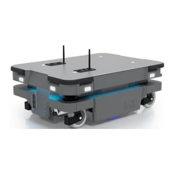
2. Product presentation 2. Product presentation MiR250 Dynamic is a component which is designed to be used as a generic base when designing an autonomous mobile robot (AMR) for a specific application. The structure and electrical interfaces allow a wide variety of top applications to be designed and integrated so that it forms a complete AMR. - Page 11 "Top compartments" on page 18 Right top compartment—see "Top compartments" on page 18 Control panel MiR250 Dynamic has a control panel in the rear-left corner of the robot. MiR250 Dynamic Integrator Manual (en) 09/2023 - v.2.1 ©Copyright 2020–2023: Mobile Industrial Robots A/S.
- Page 12 Lets the robot continue operating after the Manual stop button was pressed or after the operating mode changes. Lets the robot start operating after powering up. MiR250 Dynamic Integrator Manual (en) 09/2023 - v.2.1 ©Copyright 2020–2023: Mobile Industrial Robots A/S.
- Page 13 Manual brake release switch The Manual brake release switch is located below the control panel and releases the mechanical brakes on MiR250 Dynamic. You release the robot's mechanical brakes by turning the Manual brake release switch clockwise. MiR250 Dynamic Integrator Manual (en) 09/2023 - v.2.1 ©Copyright 2020–2023: Mobile Industrial Robots A/S.
- Page 14 Once you engage the automatic brake system, the connection to the CAN bus nodes is re- established, and the robot can update its location on the map automatically. The robot cannot operate while the mechanical brakes are released manually. MiR250 Dynamic Integrator Manual (en) 09/2023 - v.2.1 ©Copyright 2020–2023: Mobile Industrial Robots A/S.
-
Page 15: Internal Parts
2. Product presentation 2.2 Internal parts Most internal parts of MiR250 Dynamic are accessed through covers that open to different compartments—see "Accessing the internal parts" on page 127. CAUTION Removing covers from the robot exposes parts connected to the power supply, which can result in a short circuit that will damage the robot and could injure personnel. - Page 16 Rear compartment Figure 2.5 Internal parts of the rear compartment Table 2.4 Identification of internal parts in Figure 2.5 Pos. Description Pos. Description Battery Battery connector MiR250 Dynamic Integrator Manual (en) 09/2023 - v.2.1 ©Copyright 2020–2023: Mobile Industrial Robots A/S.
- Page 17 The unique nameplate of your robot is on the right side compartment cover. Make sure you do not swap the cover with covers from other robots. Figure 2.6 Internal parts of the left side compartment MiR250 Dynamic Integrator Manual (en) 09/2023 - v.2.1 ©Copyright 2020–2023: Mobile Industrial Robots A/S.
- Page 18 Pos. Description Pos. Description Switch Safe Stop 1 (SS1) contactor Bogie and drivetrain Top compartments For more information on electrical interfaces, see "Electrical interfaces" on page 105. MiR250 Dynamic Integrator Manual (en) 09/2023 - v.2.1 ©Copyright 2020–2023: Mobile Industrial Robots A/S.
-
Page 19: Light Indicators And Speaker
NOTICE Warning sounds and indicator lights must be adjusted to the site during commissioning—see MiR Commissioning Guide. You can find his guide on MiR Support Portal. MiR250 Dynamic Integrator Manual (en) 09/2023 - v.2.1 ©Copyright 2020–2023: Mobile Industrial Robots A/S. - Page 20 Figure 2.9 Light indicators on MiR250 Dynamic Table 2.8 Identification of light indicators in Figure 2.9 Pos. Description Pos. Description Signal lights Status lights MiR250 Dynamic Integrator Manual (en) 09/2023 - v.2.1 ©Copyright 2020–2023: Mobile Industrial Robots A/S.
- Page 21 When the robot's battery reaches a critically low level of power (0-1%), the ends of the status lights flash red. Signal lights Signal lights are used to indicate the robot’s immediate motion plans by signaling forwards- backwards-braking and left-right turns. MiR250 Dynamic Integrator Manual (en) 09/2023 - v.2.1 ©Copyright 2020–2023: Mobile Industrial Robots A/S.
- Page 22 In Setup > Sounds, you can upload new sounds to the robot or edit the volume and length of the default sounds. Sounds can be used in missions and zones to alert or to attract people's attention. For more information about how to set up sounds, see MiR Commissioning Guide. You can find this guide on MiR Support Portal.
- Page 23 Do not disable the sound in the safety system. This will also cause the robot to not comply with safety standards. MiR250 Dynamic Integrator Manual (en) 09/2023 - v.2.1 ©Copyright 2020–2023: Mobile Industrial Robots A/S.
-
Page 24: Safety
MiR250 Dynamic. MiR250 Dynamic is partly completed machinery, and there are steps you need to take before it can be put into operation. This manual does not cover instructions for designing, installing, or operating a complete robot system, and it does not cover local legalization. -
Page 25: Safety Message Types
3. Safety Updating the nameplate if modifications of MiR250 Dynamic are violating the data on the existing nameplate Creating a Declaration of Conformity (only applicable in the EU) Special attention must be given to the following risks with reference to the Essential Health and Safety Requirement (EHSR) from the Machinery Directive 2006/42/EC, Annex I: EHSR 1.3.7 risks related to moving parts. -
Page 26: General Safety Precautions
The robot may drive over the feet of personnel, causing injury. All personnel must be informed of the side Protective fields of the robot and be instructed to wear safety shoes near an operating robot. MiR250 Dynamic Integrator Manual (en) 09/2023 - v.2.1 ©Copyright 2020–2023: Mobile Industrial Robots A/S. - Page 27 This equipment is not intended for use in residential environments and may not provide adequate protection to radio reception in such environments. Do not use the robot in residential environments. MiR250 Dynamic Integrator Manual (en) 09/2023 - v.2.1 ©Copyright 2020–2023: Mobile Industrial Robots A/S.
- Page 28 Emergency stop function in emergency situations. Ensure that all personnel are instructed to stay clear of operating hazard zones when the robot is in the zone. MiR250 Dynamic Integrator Manual (en) 09/2023 - v.2.1 ©Copyright 2020–2023: Mobile Industrial Robots A/S.
-
Page 29: Intended Use
"Foreseeable misuse" below. 3.5 Foreseeable misuse Any use of MiR250 Dynamic deviating from the intended use is deemed as misuse. This includes, but is not limited to: Using the robot to transport people Using the robot on inclines outside the robot's specifications... -
Page 30: In Case Of Fire
MiR Support Portal. 3.7 Warning label MiR250 Dynamic is supplied with a warning label that specifies that it is strictly prohibited to ride on the robot. The label must be placed on the robot or top module so that it is clearly visible. -
Page 31: Residual Risks
Mobile Industrial Robots has identified the following potential hazards that integrators must inform personnel about and take all precautions to avoid when working with MiR250 Dynamic: You risk being run over, drawn in, trapped, or struck if you stand in the path of the robot or walk towards the robot or its intended path while it is in motion. -
Page 32: Unboxing
4. Unboxing 4. Unboxing This section describes how to unbox MiR250 Dynamic. To be able to use MiR250 Dynamic hardware version 2.0, the robot must be running software version 2.14.2 or higher. 4.1 In the box The MiR250 Dynamic robot... - Page 33 4. Unboxing Cut the protective straps surrounding the box. Remove the lid from the box. MiR250 Dynamic Integrator Manual (en) 09/2023 - v.2.1 ©Copyright 2020–2023: Mobile Industrial Robots A/S.
- Page 34 4. Unboxing Take the box with the Emergency stop box, antennas, and printed documents out of the box. Remove the pallet collars and the protective foam blocks. MiR250 Dynamic Integrator Manual (en) 09/2023 - v.2.1 ©Copyright 2020–2023: Mobile Industrial Robots A/S.
- Page 35 Use a T45 screwdriver to unscrew the mounting screw, and tighten it to 15 Nm when remounting it with the Emergency stop box. MiR250 Dynamic Integrator Manual (en) 09/2023 - v.2.1 ©Copyright 2020–2023: Mobile Industrial Robots A/S.
-
Page 36: Connecting The Battery
Screw on the two antennas, one on each top compartment. 4.3 Connecting the battery To connect the battery to the robot, you need to open the rear compartment—see "Accessing the internal parts" on page 127. MiR250 Dynamic Integrator Manual (en) 09/2023 - v.2.1 ©Copyright 2020–2023: Mobile Industrial Robots A/S. - Page 37 Pull the battery lock pin out while pushing the battery lever up. The battery lock pin will click into place and lock the battery connector once the battery lever has been pushed all the way up. MiR250 Dynamic Integrator Manual (en) 09/2023 - v.2.1 ©Copyright 2020–2023: Mobile Industrial Robots A/S.
- Page 38 Reattach the rear cover by tilting it slightly so that the bottom points forward while inserting it into the two attachment sockets. Press the two white buttons while attaching the cover to the robot. MiR250 Dynamic Integrator Manual (en) 09/2023 - v.2.1 ©Copyright 2020–2023: Mobile Industrial Robots A/S.
-
Page 39: Powering Up The Robot
Press the Power button for three seconds to turn on the robot. The status lights waver orange, and the robot starts the software initialization process. MiR250 Dynamic Integrator Manual (en) 09/2023 - v.2.1 ©Copyright 2020–2023: Mobile Industrial Robots A/S. - Page 40 Press the Resume button to clear the Protective stop. The robot is now ready for operation. If you are not able to power up the robot upon delivery, see MiR 48V Battery Technical Guide to troubleshoot the issue. You can find this guide on MiR Support Portal.
-
Page 41: Shutting Down The Robot
Press the Power button for three seconds. Wait for the robot to finish the shutdown process. The status lights waver orange, and the Power button blinks red. MiR250 Dynamic Integrator Manual (en) 09/2023 - v.2.1 ©Copyright 2020–2023: Mobile Industrial Robots A/S. -
Page 42: Connecting To The Robot Interface
You can connect to the robot using an Ethernet cable or an access point. If you are located in North America, EU, or a part of EAC, you can purchase a MiR Access Point from MiR. Outside these areas, you need to use your own access point that is approved for use in your region. If you choose to use an access point, you must ensure that the robot is disconnected from the wireless network before attaching the access point to remain compliant—see... - Page 43 If you are using an access point, connect your device to the access point. The MiR Access Point Wi-Fi has the following format: MiR_3042XXXXX. Use the password shipped with the access point to connect. MiR250 Dynamic Integrator Manual (en) 09/2023 - v.2.1 ©Copyright 2020–2023: Mobile Industrial Robots A/S.
-
Page 44: Connecting The Robot To A Wi-Fi Network
To comply with the robot's certification, you must use an Ethernet cable to avoid simultaneously active radio transmitters while setting up the connection to the local Wi-Fi network. MiR250 Dynamic Integrator Manual (en) 09/2023 - v.2.1 ©Copyright 2020–2023: Mobile Industrial Robots A/S. - Page 45 Select the network you want the robot to be connected to, and fill out the displayed fields—see the guide How to connect a MiR robot to a Wi-Fi network for more information about the Wi-Fi settings. You can find this guide on MiR Support Portal.
-
Page 46: Enabling Dynamic Footprint And Sick Configuration
Protective stop. This modifies the Personnel detection safety function—see "Field switching and Personnel detection" on page 82—such that it is no longer considered reliable. This increases the robot's braking MiR250 Dynamic Integrator Manual (en) 09/2023 - v.2.1 ©Copyright 2020–2023: Mobile Industrial Robots A/S. - Page 47 5.2 of ISO 3691-4:2020 must be performed to ensure compliance with the applicable standards. MiR expressly disclaims liability for any and all damages or injuries caused as a result of customers' failure to install, operate, and maintain the robot in strict compliance with the Integrator manual, train personnel as needed for the application, apply additional risk reduction as needed for the application, follow and implement the recommendations in these guidelines.
- Page 48 SICK configuration on MiR250, MiR500, MiR600, MiR1000, and MiR1350. You can find this guide on MiR Support Portal. Contact MiR Technical Support for the password to modify the SICK safety system. MiR250 Dynamic Integrator Manual (en) 09/2023 - v.2.1 ©Copyright 2020–2023: Mobile Industrial Robots A/S.
-
Page 49: Moving The Robot By Hand
If the robot is stuck, push or pull gently on the top bumpers or the pull handles to move the robot. Do not push or pull the robot sideways. MiR250 Dynamic Integrator Manual (en) 09/2023 - v.2.1 ©Copyright 2020–2023: Mobile Industrial Robots A/S. - Page 50 Figure 4.2 When pushing the robot, only push on the corner bumpers or top cover Figure 4.3 When pulling the robot, use either the front pull handle or the rear pull handle MiR250 Dynamic Integrator Manual (en) 09/2023 - v.2.1 ©Copyright 2020–2023: Mobile Industrial Robots A/S.
-
Page 51: Checking The Robot
"Storage" on page 54. MiR250 Dynamic Integrator Manual (en) 09/2023 - v.2.1 ©Copyright 2020–2023: Mobile Industrial Robots A/S. - Page 52 You can see the software version your robot is running in the bottom left corner of the robot interface. MiR250 Dynamic Integrator Manual (en) 09/2023 - v.2.1 ©Copyright 2020–2023: Mobile Industrial Robots A/S.
- Page 53 Check that all hardware components work as intended under Monitoring > Hardware health. All elements on the page must have the OK status and a green dot on the left. For more information, see "Error handling" on page 147. MiR250 Dynamic Integrator Manual (en) 09/2023 - v.2.1 ©Copyright 2020–2023: Mobile Industrial Robots A/S.
-
Page 54: Storage
The storage time of the robot and battery depends on the battery's state of charge, the storage conditions, and the battery version. For more information about storage time, see MiR 48V Battery Technical Guide. You can find this guide on MiR Support Portal. - Page 55 To properly troubleshoot any battery issues and for information about the exact time periods and battery voltages that trigger the transitions between states, see MiR 48V Battery Technical Guide. You can find this guide on MiR Support Portal. MiR250 Dynamic Integrator Manual (en) 09/2023 - v.2.1 ©Copyright 2020–2023: Mobile Industrial Robots A/S.
-
Page 56: Battery And Charging
Using a charging device different from the one supplied by the manufacturer can cause a fire and thereby burn injuries to nearby personnel and damage to the robot and equipment. Only use an original MiR charger. MiR250 Dynamic Integrator Manual (en) 09/2023 - v.2.1 ©Copyright 2020–2023: Mobile Industrial Robots A/S. - Page 57 Never smoke or allow an open spark or flame in the vicinity of the robot's battery. Do not use the battery for anything other than MiR250 Dynamic. MiR250 Dynamic Integrator Manual (en) 09/2023 - v.2.1 ©Copyright 2020–2023: Mobile Industrial Robots A/S.
-
Page 58: Enabling Fast Swap
Disconnect the battery—see "Disconnecting the battery" on page 61. Unscrew the two small screws mounting the status light bracket to the battery plate. Use a T20 bit. MiR250 Dynamic Integrator Manual (en) 09/2023 - v.2.1 ©Copyright 2020–2023: Mobile Industrial Robots A/S. - Page 59 Unscrew the two bolts and washers keeping the fast-swap levers raised. Use a 10 mm hex bit for the bolts and a 10 mm hex wrench to keep the nuts in place. MiR250 Dynamic Integrator Manual (en) 09/2023 - v.2.1 ©Copyright 2020–2023: Mobile Industrial Robots A/S.
- Page 60 6. Battery and charging Pull the status light bracket down and fasten the two levers to the battery lever using the same two bolts, washers, and nuts. MiR250 Dynamic Integrator Manual (en) 09/2023 - v.2.1 ©Copyright 2020–2023: Mobile Industrial Robots A/S.
-
Page 61: Disconnecting The Battery
6. Battery and charging 6.2 Disconnecting the battery MiR250 Dynamic Integrator Manual (en) 09/2023 - v.2.1 ©Copyright 2020–2023: Mobile Industrial Robots A/S. - Page 62 Pull the battery pin out while pulling the battery lever down. The battery lock pin will automatically click into place and lock the battery connector once the battery lever has been pulled all the way down. MiR250 Dynamic Integrator Manual (en) 09/2023 - v.2.1 ©Copyright 2020–2023: Mobile Industrial Robots A/S.
- Page 63 6. Battery and charging If you have enabled fast swap—"Enabling fast swap " on page 58—you can remove the battery by pulling the battery handle. MiR250 Dynamic Integrator Manual (en) 09/2023 - v.2.1 ©Copyright 2020–2023: Mobile Industrial Robots A/S.
-
Page 64: Usage
The following sections describe how the robot is operated and customized. 7.1 Work environment requirements It is the responsibility of the commissioner to ensure that the environment is suitable for MiR robots. You can find the environment and space requirements under the specifications for... - Page 65 If you intend for the robot to use elevators to travel between floors, verify that the combined weight of the robot, including load, battery, and top module does not exceed the limits of the elevator. MiR250 Dynamic Integrator Manual (en) 09/2023 - v.2.1 ©Copyright 2020–2023: Mobile Industrial Robots A/S.
-
Page 66: Operating The Robot
7. Usage Evacuation plan In MiR Fleet, it is possible to set up evacuation of robots from one or more zones in case of an emergency situation. Evacuation zones should be created and Evacuation positions should be added to the map—see the guide How to set up evacuation zones and fire alarms in MiR Fleet for more information. - Page 67 On the robot, press the Resume button. The status lights turn blue, indicating that the robot is in Manual mode. MiR250 Dynamic Integrator Manual (en) 09/2023 - v.2.1 ©Copyright 2020–2023: Mobile Industrial Robots A/S.
- Page 68 To send the robot to a selected location, open the active map, either in a dashboard or the map editor, and select Send robot to target followed by the location and orientation you want the robot to drive to. MiR250 Dynamic Integrator Manual (en) 09/2023 - v.2.1 ©Copyright 2020–2023: Mobile Industrial Robots A/S.
-
Page 69: Types Of Stop
Protective stop, internal safety contactors are switched so the robot's top module and all moving parts of the robot do not receive power. You can hear the safety contactors emit audible clicks when they are switched. MiR250 Dynamic Integrator Manual (en) 09/2023 - v.2.1 ©Copyright 2020–2023: Mobile Industrial Robots A/S. - Page 70 Resume button begins flashing blue after you have released the Emergency stop button. If the robot is in Emergency stop, it will immediately resume an operating state after you press the flashing Resume button. MiR250 Dynamic Integrator Manual (en) 09/2023 - v.2.1 ©Copyright 2020–2023: Mobile Industrial Robots A/S.
- Page 71 7. Usage Figure 7.1 MiR250 Dynamic has one Emergency stop button that must be connected through the electrical interface CAUTION Emergency stop buttons are not designed for frequent use. If a button has been used too many times, it may fail to stop the robot in an emergency situation, and nearby personnel may be injured by electrical hazards or collision with moving parts.
- Page 72 7. Usage Figure 7.2 The Manual stop button is the left-most button on the control panel MiR250 Dynamic Integrator Manual (en) 09/2023 - v.2.1 ©Copyright 2020–2023: Mobile Industrial Robots A/S.
-
Page 73: Safety-Related Functions And Interfaces
The robot computer displays the information in the robot interface (in Monitoring > Hardware health) and indicates if the robot is in Emergency or Protective stop with the status lights. MiR250 Dynamic Integrator Manual (en) 09/2023 - v.2.1 ©Copyright 2020–2023: Mobile Industrial Robots A/S. -
Page 74: Safety Functions Overview
The following terms are used in the table: PFHd: The Probability of Failure on Demand per Hour PL: Performance Level as defined in EN ISO 13849-1:2015 Architecture: As defined in EN ISO 13849-1:2015 MiR250 Dynamic Integrator Manual (en) 09/2023 - v.2.1 ©Copyright 2020–2023: Mobile Industrial Robots A/S. - Page 75 Emergecny stop device, the resulting functional safety is determined by the overall architecture and the sum of all PFHds. This includes the PFHd provided in the table. MiR250 Dynamic Integrator Manual (en) 09/2023 - v.2.1 ©Copyright 2020–2023: Mobile Industrial Robots A/S.
- Page 76 If you modify the SICK configuration file or apply another SICK configuration files, the PFHd and PL no longer apply. You must determine the new functional safety of the new configuration. This also applies if you apply MiR250 Dynamic SICK configuration. MiR250 Dynamic Integrator Manual (en) 09/2023 - v.2.1 ©Copyright 2020–2023: Mobile Industrial Robots A/S.
- Page 77 If you modify the SICK configuration file or apply another SICK configuration files, the PFHd and PL no longer apply. You must determine the new functional safety of the new configuration. This also applies if you apply MiR250 Dynamic SICK configuration. MiR250 Dynamic Integrator Manual (en) 09/2023 - v.2.1 ©Copyright 2020–2023: Mobile Industrial Robots A/S.
- Page 78 PFHds. This includes the PFHd provided in the table. MiR250 Dynamic Integrator Manual (en) 09/2023 - v.2.1 ©Copyright 2020–2023: Mobile Industrial Robots A/S.
- Page 79 PFHds. This includes the PFHd provided in the table. MiR250 Dynamic Integrator Manual (en) 09/2023 - v.2.1 ©Copyright 2020–2023: Mobile Industrial Robots A/S.
- Page 80 "Manual brake release switch" on page 13. Reaction: Category 0 stop (IEC 60204) and Architecture: mechanical spring-applied brakes engage. Category 3 The robot enters Protective stop. Reset function: N/A MiR250 Dynamic Integrator Manual (en) 09/2023 - v.2.1 ©Copyright 2020–2023: Mobile Industrial Robots A/S.
-
Page 81: Safety-Related Functions
8. Safety-related functions and interfaces 8.2 Safety-related functions The following functions are implemented in MiR250 Dynamic and are not dependent on a top module. Emergency stop The Emergency stop function ensures that activation of the external Emergency stop box will trigger the robot into Emergency stop. - Page 82 Personnel detection function is no longer considered reliable and the Protective fields listed in "Field switching and Personnel detection" above no longer applies to the robot. MiR250 Dynamic Integrator Manual (en) 09/2023 - v.2.1 ©Copyright 2020–2023: Mobile Industrial Robots A/S.
- Page 83 Scanners measure distances to diffuse reflections, which means that a tolerance is added to the Protective fields to secure a safe detection of persons crossing the Protective fields. The tolerance distance is 65 mm. MiR250 Dynamic Integrator Manual (en) 09/2023 - v.2.1 ©Copyright 2020–2023: Mobile Industrial Robots A/S.
- Page 84 0.90 to 1.30 m/s 1 245 mm 210 mm 110 mm 1.30 to 1.70 m/s 1 915 mm 210 mm 110 mm 1.70 to 2.10 m/s 2 855 mm 210 mm 110 mm MiR250 Dynamic Integrator Manual (en) 09/2023 - v.2.1 ©Copyright 2020–2023: Mobile Industrial Robots A/S.
- Page 85 The Protective fields for driving backward are the same as the fields for driving forward. The cases in Table 8.3 correspond to the fields shown in Figure 8.3. MiR250 Dynamic Integrator Manual (en) 09/2023 - v.2.1 ©Copyright 2020–2023: Mobile Industrial Robots A/S.
- Page 86 210 mm 105 mm 0.50 to 0.90 m/s 655 mm 210 mm 105 mm 0.90 to 1.30 m/s 1 095 mm 210 mm 105 mm Figure 8.3 The Protective field contours when the robot drives backward MiR250 Dynamic Integrator Manual (en) 09/2023 - v.2.1 ©Copyright 2020–2023: Mobile Industrial Robots A/S.
- Page 87 Protective fields. This muting is by default enabled in the template missions for docking to known markers such as charging stations or pallet racks, or it can manually be configured for any customized mission. MiR250 Dynamic Integrator Manual (en) 09/2023 - v.2.1 ©Copyright 2020–2023: Mobile Industrial Robots A/S.
- Page 88 There are two ways you can mute the Protective fields using the robot interface. You can add the Mute protective fields action to a mission: Enable Mute protective fields under System > Settings > Features. MiR250 Dynamic Integrator Manual (en) 09/2023 - v.2.1 ©Copyright 2020–2023: Mobile Industrial Robots A/S.
- Page 89 Add the action Mute protective fields from the Safety system menu. Edit the action parameters so the Protective fields are muted. MiR250 Dynamic cannot mute specific Protective fields; you can either mute all or none of the fields. Otherwise, the robot reports an error.
- Page 90 The Protective fields will remain muted during any Relative move action that comes right after the docking action. The Protective fields will also remain muted if you engage the Manual brake release—see "Manual brake release switch" on page 13. MiR250 Dynamic Integrator Manual (en) 09/2023 - v.2.1 ©Copyright 2020–2023: Mobile Industrial Robots A/S.
-
Page 91: Safety-Related Interfaces For Top Modules
Signal to enter Protective stop If both pins deliver 24 V to the robot, it can If both of the pins deliver 0 V, the robot operate. enters Protective stop. MiR250 Dynamic Integrator Manual (en) 09/2023 - v.2.1 ©Copyright 2020–2023: Mobile Industrial Robots A/S. - Page 92 0 V signal to the top module becomes 24 V. through the Auxiliary safety function interface. Pins 5 in interfaces A and B of the Auxiliary safety functions are used for the Locomotion function. MiR250 Dynamic Integrator Manual (en) 09/2023 - v.2.1 ©Copyright 2020–2023: Mobile Industrial Robots A/S.
- Page 93 The System emergency stop function can be used if the top module has its own Emergency stop circuit. Use this function to make it so both MiR250 Dynamic and the top module are brought into Emergency stop when either system is triggered.
- Page 94 Default speed If both pins are 0 V, the robot drives at The robot drives at its default speed only 0.3 m/s. when both inputs are 24 V. MiR250 Dynamic Integrator Manual (en) 09/2023 - v.2.1 ©Copyright 2020–2023: Mobile Industrial Robots A/S.
- Page 95 8. Safety-related functions and interfaces Pins 4 in interfaces A and B of the Auxiliary safety functions are used for the Reduced speed function. MiR250 Dynamic Integrator Manual (en) 09/2023 - v.2.1 ©Copyright 2020–2023: Mobile Industrial Robots A/S.
-
Page 96: Mounting A Top Module
ISO 12100. MiR250 Dynamic Integrator Manual (en) 09/2023 - v.2.1 ©Copyright 2020–2023: Mobile Industrial Robots A/S. - Page 97 Stay within the specifications for weight and the total payload’s center of gravity— "Payload distribution" on page 98. MiR250 Dynamic Integrator Manual (en) 09/2023 - v.2.1 ©Copyright 2020–2023: Mobile Industrial Robots A/S.
-
Page 98: Payload Distribution
WARNING Load falling or robot overturning if the load on MiR250 Dynamic is not positioned or fastened correctly can cause damage to equipment and injury to personnel. Ensure that the load is positioned according to the specifications and is fastened correctly. -
Page 99: Side View
10. Payload distribution 10.1 Side view Figure 10.1 The center of mass (CoM) of payloads at 1.2 m/s with no incline MiR250 Dynamic Integrator Manual (en) 09/2023 - v.2.1 ©Copyright 2020–2023: Mobile Industrial Robots A/S. - Page 100 10. Payload distribution Figure 10.2 The center of mass (CoM) of payloads seen from the side at 2.0 m/s with no incline MiR250 Dynamic Integrator Manual (en) 09/2023 - v.2.1 ©Copyright 2020–2023: Mobile Industrial Robots A/S.
-
Page 101: Front View
10. Payload distribution 10.2 Front view Figure 10.3 The center of mass (CoM) of payloads seen from the front at 1.2 m/s with no incline MiR250 Dynamic Integrator Manual (en) 09/2023 - v.2.1 ©Copyright 2020–2023: Mobile Industrial Robots A/S. - Page 102 10. Payload distribution Figure 10.4 The center of mass (CoM) of payloads seen from the front at 2.0 m/s with no incline MiR250 Dynamic Integrator Manual (en) 09/2023 - v.2.1 ©Copyright 2020–2023: Mobile Industrial Robots A/S.
-
Page 103: Top View
10. Payload distribution 10.3 Top view Figure 10.5 The center of mass (CoM) of payloads seen from the top at 1.2 m/s with no incline MiR250 Dynamic Integrator Manual (en) 09/2023 - v.2.1 ©Copyright 2020–2023: Mobile Industrial Robots A/S. - Page 104 10. Payload distribution Figure 10.6 The center of mass (CoM) of payloads seen from the top MiR250 Dynamic Integrator Manual (en) 09/2023 - v.2.1 ©Copyright 2020–2023: Mobile Industrial Robots A/S.
-
Page 105: Electrical Interfaces
This section describes the general purpose interfaces located in the left side compartment on top of MiR250 Dynamic. Emergency stop For more information on how to use the Emergency stop interface, see "Emergency stop" on page 81. MiR250 Dynamic Integrator Manual (en) 09/2023 - v.2.1 ©Copyright 2020–2023: Mobile Industrial Robots A/S. - Page 106 Standard function: Return for lamp signal. Signal name: Test output 1 Type: Output Standard function: Safety output 1. Should be connected through Emergency stop buttons to pin 4. MiR250 Dynamic Integrator Manual (en) 09/2023 - v.2.1 ©Copyright 2020–2023: Mobile Industrial Robots A/S.
- Page 107 Standard function: Safety input 3. When receiving 24 V will restart the Emergency stop. Signal name: RST_LAMP_24_V Type: Output Standard function: 24 V output for powering the lamp on the Emergency stop box. MiR250 Dynamic Integrator Manual (en) 09/2023 - v.2.1 ©Copyright 2020–2023: Mobile Industrial Robots A/S.
- Page 108 Never connect power and ground signals to the chassis, and never stack the 24 V and 48 V power supplies. MiR250 Dynamic Integrator Manual (en) 09/2023 - v.2.1 ©Copyright 2020–2023: Mobile Industrial Robots A/S.
- Page 109 If your device has a higher capacitance, you must integrate your own softstarter that keeps the current under 2 A for the first 100 ms, and thereafter under 10 A. MiR250 Dynamic Integrator Manual (en) 09/2023 - v.2.1 ©Copyright 2020–2023: Mobile Industrial Robots A/S.
- Page 110 2 A for the first 100 ms, and thereafter under 10 A. Signal name: GND Type: Ground Standard function: Power ground. MiR250 Dynamic Integrator Manual (en) 09/2023 - v.2.1 ©Copyright 2020–2023: Mobile Industrial Robots A/S.
- Page 111 Protective stop. Signal name: Isolated GND Type: Ground Standard function: Must be used with pin 5 to be galvanically isolated from the rest of the robot. Unassigned MiR250 Dynamic Integrator Manual (en) 09/2023 - v.2.1 ©Copyright 2020–2023: Mobile Industrial Robots A/S.
- Page 112 Various protocols can be supported, for example Modbus. For more information on how to use Modbus, see the guide How to use Modbus with MiR robots. You can find this guide on MiR Support Portal. Table 11.3 Description of the pins in the Ethernet interface Pin no.
-
Page 113: Right Side Interfaces
The shelf feature uses a different kind of communication that is specific to the MiR top modules. MiR250 Dynamic Integrator Manual (en) 09/2023 - v.2.1 ©Copyright 2020–2023: Mobile Industrial Robots A/S. - Page 114 Figure 11.5 Example of I2 registered as high by the robot Output pins must be connected to RTN pins, and input pins must be connected to 24 V pins. MiR250 Dynamic Integrator Manual (en) 09/2023 - v.2.1 ©Copyright 2020–2023: Mobile Industrial Robots A/S.
- Page 115 Pin no. Description Signal name: OUT1 Type: Output Standard function: Output 1. Maximum 1 A at 24 V. Signal name: GND Type: Ground Standard function: Protected return. MiR250 Dynamic Integrator Manual (en) 09/2023 - v.2.1 ©Copyright 2020–2023: Mobile Industrial Robots A/S.
- Page 116 Standard function: Protected return. Signal name: OUT4 Type: Output Standard function: Output 4. Maximum 1 A at 24 V. Signal name: GND Type: Ground Standard function: Protected return. MiR250 Dynamic Integrator Manual (en) 09/2023 - v.2.1 ©Copyright 2020–2023: Mobile Industrial Robots A/S.
- Page 117 Standard function: Input 2. Signal name: 24V Type: Output Standard function: 24 V output. 2 A maximum. Signal name: IN3 Type: Input Standard function: Input 3. MiR250 Dynamic Integrator Manual (en) 09/2023 - v.2.1 ©Copyright 2020–2023: Mobile Industrial Robots A/S.
- Page 118 Auxiliary Safety Functions A and B The Auxiliary safety functions interfaces are designed to support Emergency and Protective stops and other safety functions—see "Safety-related interfaces for top modules" on page 91. MiR250 Dynamic Integrator Manual (en) 09/2023 - v.2.1 ©Copyright 2020–2023: Mobile Industrial Robots A/S.
- Page 119 Standard function: When inactive, the robot enters Protective stop. If this pin and the other Safeguarded stop pin are unequally set for a period greater than three seconds, the robot must be restarted. MiR250 Dynamic Integrator Manual (en) 09/2023 - v.2.1 ©Copyright 2020–2023: Mobile Industrial Robots A/S.
- Page 120 Table 11.7 Description of the pins in the Auxiliary safety function interface B Pin no. Description Signal name: Test output 2 Type: Output Standard function: 24 V out test signal. Sends test pulses (not on constantly). MiR250 Dynamic Integrator Manual (en) 09/2023 - v.2.1 ©Copyright 2020–2023: Mobile Industrial Robots A/S.
- Page 121 Signal name: Shared E-Stop out 2 Type: Output Standard function: Is active when the robot is standing still. Signal name: SAFE_RETURN Standard function: Safe return for output signals. MiR250 Dynamic Integrator Manual (en) 09/2023 - v.2.1 ©Copyright 2020–2023: Mobile Industrial Robots A/S.
-
Page 122: Connector List
Auxiliary safety Single wire Phoenix Contact 1851274 functions - short connector, female, connector pitch 3.81 mm, 6- Antenna Cable connector, AMPHENOL RF RSMA1111A1- RP-SMA, male, gold 3GT50G-1A-50 MiR250 Dynamic Integrator Manual (en) 09/2023 - v.2.1 ©Copyright 2020–2023: Mobile Industrial Robots A/S. - Page 123 11. Electrical interfaces Figure 11.8 Connector dimensions for the Power connector MiR250 Dynamic Integrator Manual (en) 09/2023 - v.2.1 ©Copyright 2020–2023: Mobile Industrial Robots A/S.
-
Page 124: Specifications
MiR 48V Battery Battery type Lithium-ion Battery weight 14 kg Battery dimensions 495×210×75 mm Environment Maximum incline/decline 5% at 0.5 m/s Maximum traversable gap 20 mm Maximum traversable step 20 mm MiR250 Dynamic Integrator Manual (en) 09/2023 - v.2.1 ©Copyright 2020–2023: Mobile Industrial Robots A/S. - Page 125 We recommend either avoiding these materials, covering them with opaque and matte material the robot can detect, or ensuring the robot does not operate in areas with these materials. MiR250 Dynamic Integrator Manual (en) 09/2023 - v.2.1 ©Copyright 2020–2023: Mobile Industrial Robots A/S.
-
Page 126: Maintenance
Disconnect the battery—see "Disconnecting the battery" on page 61. If the maintenance can not be performed with battery disconnected ensure that MiR250 Dynamic is set in Locked mode. MiR250 Dynamic Integrator Manual (en) 09/2023 - v.2.1 ©Copyright 2020–2023: Mobile Industrial Robots A/S. -
Page 127: Accessing The Internal Parts
13. Maintenance 13.2 Accessing the internal parts Most internal parts of MiR250 Dynamic are accessed through covers that open to different compartments. See a video of the process on the MiR TechComm videos channel on vimeo.com. CAUTION Removing covers from the robot exposes parts connected to the power supply, which can result in a short circuit that will damage the robot and could injure personnel. - Page 128 Loosen the bottom corners one at the time by pulling out each corner. Loosen the top corners one at the time by pulling each corner down, and then out. MiR250 Dynamic Integrator Manual (en) 09/2023 - v.2.1 ©Copyright 2020–2023: Mobile Industrial Robots A/S.
- Page 129 Pull off the cover. Rear compartment To open the rear compartment, follow these steps: Push the two white buttons on the rear cover at the same time. MiR250 Dynamic Integrator Manual (en) 09/2023 - v.2.1 ©Copyright 2020–2023: Mobile Industrial Robots A/S.
- Page 130 Loosen the bottom corners one at the time by pulling out each corner. Loosen the top corners one at the time by pulling each corner down, and then out. MiR250 Dynamic Integrator Manual (en) 09/2023 - v.2.1 ©Copyright 2020–2023: Mobile Industrial Robots A/S.
- Page 131 To open a side compartment, follow these steps: Remove the front cover and rear cover—see "Front compartment" on page 127 "Rear compartment" on page 129. Turn the two screws counterclockwise. Use a T30 bit. MiR250 Dynamic Integrator Manual (en) 09/2023 - v.2.1 ©Copyright 2020–2023: Mobile Industrial Robots A/S.
- Page 132 13. Maintenance Loosen the bottom corners one at the time by pulling out each corner. Pull off the cover. MiR250 Dynamic Integrator Manual (en) 09/2023 - v.2.1 ©Copyright 2020–2023: Mobile Industrial Robots A/S.
- Page 133 Unscrew and remove the antenna from the top cover. Unscrew the nut from the antenna connector, and push the antenna cable free of the cover. Use a 10 mm wrench. MiR250 Dynamic Integrator Manual (en) 09/2023 - v.2.1 ©Copyright 2020–2023: Mobile Industrial Robots A/S.
-
Page 134: Periodic Checks
Unscrew the four screws. Use a T8 bit. Pull off the cover. 13.3 Periodic checks The following maintenance schedules give an overview of regular cleaning and parts replacement procedures. MiR250 Dynamic Integrator Manual (en) 09/2023 - v.2.1 ©Copyright 2020–2023: Mobile Industrial Robots A/S. - Page 135 Regular weekly checks and maintenance tasks Once a week, carry out the maintenance tasks in Table 13.1. MiR250 Dynamic Integrator Manual (en) 09/2023 - v.2.1 ©Copyright 2020–2023: Mobile Industrial Robots A/S.
- Page 136 Check if the safety markings around operating hazard zones are the floor intact and visible. Information Check if the safety stickers, identification label, and nameplate on stickers the robot are still intact and visible. MiR250 Dynamic Integrator Manual (en) 09/2023 - v.2.1 ©Copyright 2020–2023: Mobile Industrial Robots A/S.
- Page 137 Robot reports contamination scanners on MiR250. errors. If only the optics cover is damaged, you can replace the cover alone. See SICK's documentation for nanoScan3 for instructions. MiR250 Dynamic Integrator Manual (en) 09/2023 - v.2.1 ©Copyright 2020–2023: Mobile Industrial Robots A/S.
- Page 138 If you replace the cover with the robot's nameplate, make sure to mount a new copy of the nameplate to the replacement cover. MiR250 Dynamic Integrator Manual (en) 09/2023 - v.2.1 ©Copyright 2020–2023: Mobile Industrial Robots A/S.
- Page 139 To test the cameras, see the guide How to test if the 3D cameras are working on MiR robots. To calibrate, see the guide How to calibrate a D435 3D camera. MiR250 Dynamic Integrator Manual (en) 09/2023 - v.2.1 ©Copyright 2020–2023: Mobile Industrial Robots A/S.
- Page 140 Push down the bring the robot into Emergency red button, and check that the stop. Emergency stop reset button lights up and that the status lights turn red. MiR250 Dynamic Integrator Manual (en) 09/2023 - v.2.1 ©Copyright 2020–2023: Mobile Industrial Robots A/S.
- Page 141 How to replace the drive wheels on MiR250. The robot's IMU must be calibrated after replacement of the wheels—see the guide How to calibrate the IMU. MiR250 Dynamic Integrator Manual (en) 09/2023 - v.2.1 ©Copyright 2020–2023: Mobile Industrial Robots A/S.
- Page 142 122 mm. Replace all four caster wheels together. See the guide How to replace the caster wheels on MiR250. MiR250 Dynamic Integrator Manual (en) 09/2023 - v.2.1 ©Copyright 2020–2023: Mobile Industrial Robots A/S.
- Page 143 STO and Replace to ensure the reliability The robot begins reporting dynamic brake of the robot's safety functions. contactor errors. contactors MiR250 Dynamic Integrator Manual (en) 09/2023 - v.2.1 ©Copyright 2020–2023: Mobile Industrial Robots A/S.
- Page 144 For storage of the battery, see "Storage" on page 54. For disposal of the battery, see "Disposal" on page 160. MiR250 Dynamic Integrator Manual (en) 09/2023 - v.2.1 ©Copyright 2020–2023: Mobile Industrial Robots A/S.
-
Page 145: Updating Software
When updating a MiR250 Dynamic, keep the following points in mind: Never turn off MiR250 Dynamic during the update process. If your robot has a MiR hook mounted to it, make sure to update the hook software before updating the robot software. - Page 146 13. Maintenance For more information on how to create, roll back, and delete backups, see MiR Robot Interface Guide. You can find this guide on MiR Support Portal. MiR250 Dynamic Integrator Manual (en) 09/2023 - v.2.1 ©Copyright 2020–2023: Mobile Industrial Robots A/S.
-
Page 147: Error Handling
Use Try/Catch actions to make the robot react in a specific way if it fails to execute certain actions. MiR250 Dynamic Integrator Manual (en) 09/2023 - v.2.1 ©Copyright 2020–2023: Mobile Industrial Robots A/S. -
Page 148: Hardware Errors
For more information about commissioning your robot to fulfill these guidelines, and for setting up missions and error handling, see MiR Robot Interface Guide and MiR Commissioning Guide. You can find these guides on MiR Support Portal. -
Page 149: Error Codes And Solutions
You can find these guides on MiR Support Portal. 14.3 Error codes and solutions Use the MiR troubleshooting guide to resolve many of the errors the robot reports. You can find these guides on MiR Support Portal. Table 14.1 Common error codes the robot reports... - Page 150 Unsupported SICK Requires errors in the safety system, we cannot program version. interaction. troubleshoot programs with custom modifications. Refer to the solution in error "1003" above. MiR250 Dynamic Integrator Manual (en) 09/2023 - v.2.1 ©Copyright 2020–2023: Mobile Industrial Robots A/S.
- Page 151 Consider adding a Try/Catch action to provide the robot with an alternative action if the attempted action failed. This will prevent the error from appearing in future cases. MiR250 Dynamic Integrator Manual (en) 09/2023 - v.2.1 ©Copyright 2020–2023: Mobile Industrial Robots A/S.
- Page 152 Consider adding a Try/Catch action to provide the robot with an alternative action if the attempted action failed. This will prevent the error from appearing in future cases. MiR250 Dynamic Integrator Manual (en) 09/2023 - v.2.1 ©Copyright 2020–2023: Mobile Industrial Robots A/S.
- Page 153 This often occurs if the active map does not include enough landmarks or includes dynamic obstacles that are no longer there. MiR250 Dynamic Integrator Manual (en) 09/2023 - v.2.1 ©Copyright 2020–2023: Mobile Industrial Robots A/S.
- Page 154 Technical Support for analysis. For a full list of MiR error codes, see Error codes and solutions on MiR Support Portal. MiR250 Dynamic Integrator Manual (en) 09/2023 - v.2.1 ©Copyright 2020–2023: Mobile Industrial Robots A/S.
-
Page 155: Transportation
Remove the four M8 mounting bolts in the top plate of the robot. Use a T45 bit. Tighten the bolts to 15 Nm when remounting them. MiR250 Dynamic Integrator Manual (en) 09/2023 - v.2.1 ©Copyright 2020–2023: Mobile Industrial Robots A/S. - Page 156 The eye bolts should be oriented in parallel to the opposite diagonal bolt to ensure stable lifting. Use an appropriate lifting device to lift the robot. The lifting device should be capable of lifting at least 400 kg. MiR250 Dynamic Integrator Manual (en) 09/2023 - v.2.1 ©Copyright 2020–2023: Mobile Industrial Robots A/S.
-
Page 157: Packing The Robot For Transportation
Protective foam blocks: Side blocks and the top layer Protective corner braces To pack the robot, repeat the steps in "Unpacking MiR250 Dynamic" on page 32 in the reverse order. MiR250 Dynamic Integrator Manual (en) 09/2023 - v.2.1 ©Copyright 2020–2023: Mobile Industrial Robots A/S. -
Page 158: Transporting The Battery
Do not expose the battery to direct sunlight. Do not expose the battery to temperatures above 35° C. Do not expose the battery to air humidity above 85%. MiR250 Dynamic Integrator Manual (en) 09/2023 - v.2.1 ©Copyright 2020–2023: Mobile Industrial Robots A/S. - Page 159 Never smoke or allow an open spark or flame in the vicinity of the robot's battery. Do not use the battery for anything other than MiR250 Dynamic. MiR250 Dynamic Integrator Manual (en) 09/2023 - v.2.1 ©Copyright 2020–2023: Mobile Industrial Robots A/S.
-
Page 160: Disposal
A recycling label indicates that the battery needs to be recycled and not disposed as municipal waste—see Figure 16.1. Contact your distributor to get specific information about their take back service. Figure 16.1 Battery disposal symbols MiR250 Dynamic Integrator Manual (en) 09/2023 - v.2.1 ©Copyright 2020–2023: Mobile Industrial Robots A/S. -
Page 161: Commissioning Overview
Only persons assigned with the commissioning task should be present during commissioning. MiR Commissioning Guide contains a site acceptance checklist with the core tasks that are part of commissioning the MiR robot. - Page 162 17. Commissioning overview Figure 17.1 Flow diagram of the commissioning process MiR250 Dynamic Integrator Manual (en) 09/2023 - v.2.1 ©Copyright 2020–2023: Mobile Industrial Robots A/S.
-
Page 163: Glossary
Emergency stop. To do this, you must release the Emergency stop button and then press the Resume button. MiR250 Dynamic Integrator Manual (en) 09/2023 - v.2.1 ©Copyright 2020–2023: Mobile Industrial Robots A/S. - Page 164 MiR250 Dynamic; and ensuring the safety of nearby personnel when a MiR robot is accelerating, braking, and maneuvering. Typically, an Integrator commissions a system on behalf of a system manufacturer (e.g.
- Page 165 Marker type A marker type is a description of a shelf that MiR robots can dock to. You must have a marker type for each type and size of shelf you want your robot to be able to transport.
- Page 166 18. Glossary MiR robot interface The MiR robot interface is the web-based interface that enables you to control your MiR robot. It is accessed by connecting to the same network as the robot and entering the robot's IP address in a browser.
- Page 167 Operator Operators have thorough knowledge of MiR250 Dynamic and of the safety precautions presented in the User guide of MiR250 Dynamic. Operators have the following main tasks: servicing and maintainingthe robot, and creating and changing missions and map positions in the robot interface.
- Page 168 These must be included on the map and are used by the robot to localize itself. X-Y coordinates The robot's map is based on a Cartesian coordinate system. Every point on the map can be defined as an X-Y coordinate. MiR250 Dynamic Integrator Manual (en) 09/2023 - v.2.1 ©Copyright 2020–2023: Mobile Industrial Robots A/S.
- Page 169 18. Glossary MiR250 Dynamic Integrator Manual (en) 09/2023 - v.2.1 ©Copyright 2020–2023: Mobile Industrial Robots A/S.
- Page 170 18. Glossary Doc. no.: 301005 MiR250 Dynamic Integrator Manual (en) 09/2023 - v.2.1 ©Copyright 2020–2023: Mobile Industrial Robots A/S.
Need help?
Do you have a question about the MiR250 Dynamic and is the answer not in the manual?
Questions and answers