MIR MIR250 User Manual
Hide thumbs
Also See for MIR250:
- User manual (249 pages) ,
- Manual (195 pages) ,
- Installer/integrator manual (170 pages)
Table of Contents
Advertisement
Quick Links
Advertisement
Table of Contents

Related Manuals for MIR MIR250


Summary of Contents for MIR MIR250
- Page 1 User Guide (en) Date: 07/2020 Revision: v.1.2...
- Page 2 Copyright © 2020 by Mobile Industrial Robots A/S. Contact the manufacturer: Mobile Industrial Robots A/S Emil Neckelmanns Vej 15F DK-5220 Odense SØ the MiR website Phone: +45 20 377 577 Email: support@mir-robots.com CVR: 35251235 MiR250 User Guide (en) 07/2020 - v.1.2 ©Copyright 2020: Mobile Industrial Robots A/S.
-
Page 3: Table Of Contents
4.1 Safety message types 4.2 General safety precautions 4.3 Intended use 4.4 Users 4.5 Foreseeable misuse 4.6 Warning label 4.7 Residual risks 5. Getting started 5.1 In the box MiR250 User Guide (en) 07/2020 - v.1.2 ©Copyright 2020: Mobile Industrial Robots A/S. - Page 4 8. Navigation and control system 8.1 System overview 8.2 User input 8.3 Global planner 8.4 Local planner 8.5 Obstacle detection 8.6 Localization 8.7 Motor controller and motors MiR250 User Guide (en) 07/2020 - v.1.2 ©Copyright 2020: Mobile Industrial Robots A/S.
- Page 5 10.4 Creating markers and positions 10.5 Creating a mission 10.6 Creating a footprint 10.7 Operating hazard zones 10.8 Brake test 10.9 Creating user groups and users 10.10 Creating dashboards MiR250 User Guide (en) 07/2020 - v.1.2 ©Copyright 2020: Mobile Industrial Robots A/S.
- Page 6 14.1 Original packaging 14.2 Packing the robot for transportation 14.3 Battery 15. Disposal of robot 16. Payload specifications 16.1 Side view 16.2 Front view 16.3 Top view MiR250 User Guide (en) 07/2020 - v.1.2 ©Copyright 2020: Mobile Industrial Robots A/S.
- Page 7 17. Interface specifications 17.1 Left side interfaces 17.2 Right side interfaces 17.3 Connector list 18. Error handling 18.1 Software errors 18.2 Hardware errors MiR250 User Guide (en) 07/2020 - v.1.2 ©Copyright 2020: Mobile Industrial Robots A/S.
-
Page 8: About This Document
1. About this document 1. About this document This user guide explains how to set up and start operating your MiR250 and provides examples of simple missions you can expand to your purposes. This guide also contains information regarding the external and internal components of MiR250 along with a guide for proper maintenance of the robot. -
Page 9: Version History
This table shows current and previous versions of this document. Revision Release date Description 2020-06-26 First edition 2020-07-01 Minor corrections throughout manual. 2020-07-08 Minor correction throughout manual. Changes in Operating hazard zones on page 135. MiR250 User Guide (en) 07/2020 - v.1.2 ©Copyright 2020: Mobile Industrial Robots A/S. -
Page 10: Product Presentation
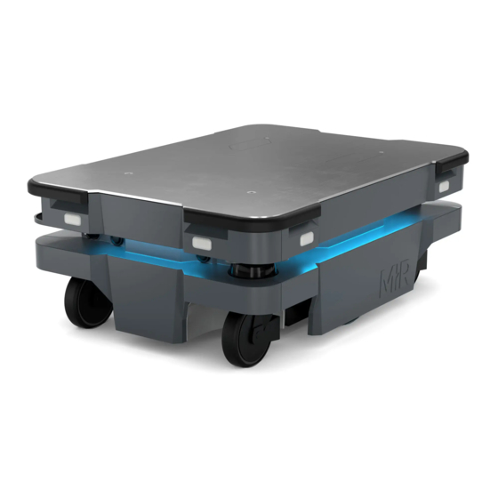
2. Product presentation 2. Product presentation MiR250 is an autonomous mobile robot that can transport loads up to 250 kg indoors within production facilities, warehouses, and other industrial locations where access to the public is restricted. Users operate MiR250 via a web-based user interface, which is accessed via a browser on a PC, smartphone, or tablet. -
Page 11: Main Features Of Mir250
Creating the Try/Catch mission page 155. • Automatic deceleration for objects The built-in sensors ensure that the robot is slowed down when obstacles are detected in front of it. MiR250 User Guide (en) 07/2020 - v.1.2 ©Copyright 2020: Mobile Industrial Robots A/S. -
Page 12: Top Modules
The following top modules are available for MiR250: • MiR 250 Shelf Carrier A top application that allows MiR250 to tow shelves. To read more about the top modules, go to the MiR website. MiR250 User Guide (en) 07/2020 - v.1.2 ©Copyright 2020: Mobile Industrial Robots A/S. -
Page 13: External Parts
2. Product presentation 2.3 External parts This section presents the parts of MiR250 that are visible on the outside. Pos. Description Pos. Description Corner bumper: four pcs, one Front cover: opens to front on each corner compartment—see Internal parts on page 20... - Page 14 Right top compartment: Access to Safe I/Os and GPIO interface. Antenna RP-SMA connector is available on the top side of the hatch—see Internal parts on page 20 MiR250 User Guide (en) 07/2020 - v.1.2 ©Copyright 2020: Mobile Industrial Robots A/S.
- Page 15 MiR250 is delivered with an identification label mounted to the product. The identification label identifies the product, the product serial number, and the hardware version of the product. The identification label of MiR250 is located behind the rear cover next to the battery. Figure 2.1. Example of a MiR250 identification label. Nameplate Every MiR application is delivered with a nameplate that must be mounted to the robot.
- Page 16 Puts the robot in Autonomous mode. • Middle position: Locked Locks the robot. The robot blocks the wheels; you cannot start a mission or drive the robot manually. MiR250 User Guide (en) 07/2020 - v.1.2 ©Copyright 2020: Mobile Industrial Robots A/S.
- Page 17 Operating modes on page 19. The control panel buttons The following table identifies the three buttons on the control panel. Pos. Description Pos. Description Manual stop Resume Power MiR250 User Guide (en) 07/2020 - v.1.2 ©Copyright 2020: Mobile Industrial Robots A/S.
- Page 18 Manual brake release switch The manual brake release switch is located below the control panel and releases the mechanical brakes on MiR250. You release the brakes by turning the Manual brake release switch clockwise. MiR250 User Guide (en) 07/2020 - v.1.2 ©Copyright 2020: Mobile Industrial Robots A/S.
- Page 19 Manual mode. For information about activating this mode—see Driving the robot in Manual mode on page 49. MiR250 User Guide (en) 07/2020 - v.1.2 ©Copyright 2020: Mobile Industrial Robots A/S.
-
Page 20: Internal Parts
In autonomous mode, the joystick is disabled in the robot interface. 2.4 Internal parts Most internal parts of MiR250 are accessed through covers that open to different compartments: •... - Page 21 PLC. The battery and Battery disconnect lever can be accessed without the use of tools. The other components in the rear compartment are only accessible via use of tools. MiR250 User Guide (en) 07/2020 - v.1.2 ©Copyright 2020: Mobile Industrial Robots A/S.
- Page 22 Battery Cable charging interface Power board for motor Safety PLC controller, robot computer, and safety PLC Side compartments The side compartments contain the bogies and drive wheels. MiR250 User Guide (en) 07/2020 - v.1.2 ©Copyright 2020: Mobile Industrial Robots A/S.
- Page 23 Bogie and drivetrain consisting of Safe Torque Off (STO) contactor motor, gearbox, encoder, brake, drive wheel, and assembly parts The right side compartment contains the following components: MiR250 User Guide (en) 07/2020 - v.1.2 ©Copyright 2020: Mobile Industrial Robots A/S.
- Page 24 Top compartments The two top compartments contain electrical interfaces that can be connected to top modules. To open a top compartment, see Accessing the internal parts on page 26. MiR250 User Guide (en) 07/2020 - v.1.2 ©Copyright 2020: Mobile Industrial Robots A/S.
- Page 25 Interface specifications on page 192. Pos. Description Pos. Description Emergency stop Auxiliary power connector Ethernet General purpose I/Os Auxiliary safety functions I/Os MiR250 User Guide (en) 07/2020 - v.1.2 ©Copyright 2020: Mobile Industrial Robots A/S.
-
Page 26: Accessing The Internal Parts
3. Accessing the internal parts 3. Accessing the internal parts Most internal parts of MiR250 are accessed through covers that open to different compartments: • Front compartment • Rear compartment • Side compartments • Top compartments CAUTION Removing covers from the robot exposes parts connected to the power supply, risking damage to the robot from a short circuit and electrical shock to personnel. -
Page 27: Rear Compartment
Pull the front cover off of the robot. 3.2 Rear compartment Follow these steps to open the rear compartment: Push the two white buttons at the same time. MiR250 User Guide (en) 07/2020 - v.1.2 ©Copyright 2020: Mobile Industrial Robots A/S. - Page 28 3. Accessing the internal parts Loosen the cover by wiggling both sides. Pull off the cover. MiR250 User Guide (en) 07/2020 - v.1.2 ©Copyright 2020: Mobile Industrial Robots A/S.
-
Page 29: Side Compartments
If you need to remove a cover completely, the antenna cable needs to be detached from the cover first. When reattaching the covers, make sure that the antenna cables are not damaged. MiR250 User Guide (en) 07/2020 - v.1.2 ©Copyright 2020: Mobile Industrial Robots A/S. - Page 30 3. Accessing the internal parts Figure 3.1. The top compartments of MiR250. MiR250 User Guide (en) 07/2020 - v.1.2 ©Copyright 2020: Mobile Industrial Robots A/S.
-
Page 31: Safety
Alerts against unsafe practices. Carefully read the message that follows to prevent minor or moderate injury. NOTICE Indicates important information, including situations that can result in damage to equipment or property. MiR250 User Guide (en) 07/2020 - v.1.2 ©Copyright 2020: Mobile Industrial Robots A/S. -
Page 32: General Safety Precautions
WARNING MiR250 may drive over the feet of personnel, causing injury. • All personnel must be informed of the side protective fields of MiR250 and be instructed to wear safety shoes near an operating robot. WARNING Contact with live electrical parts can cause electric shock. - Page 33 Mark descending staircases and holes as forbidden zones on maps. • Keep the maps up to date. • Inform personnel that the robot cannot detect descending staircases and holes in the floor in time to stop. MiR250 User Guide (en) 07/2020 - v.1.2 ©Copyright 2020: Mobile Industrial Robots A/S.
- Page 34 Modifications or manipulations of the battery may lead to considerable safety risks and are therefore prohibited. • Do not use the battery on anything other than MiR250. MiR250 User Guide (en) 07/2020 - v.1.2 ©Copyright 2020: Mobile Industrial Robots A/S.
-
Page 35: Intended Use
MiR250 is equipped with safety-related features that are purposely designed for collaborative operation where the robot operates without a safety enclosure or together with people. MiR250 is intended to be used with top modules supported by MiR or custom modules that: • Do not have any moving parts. -
Page 36: Users
4. Safety MiR250 is designed for and all risks are considered when used with one of the following types of top modules: • MiR Shelf Carrier 250 to transport wheeled carts. MiR250 can be used as a partly complete machine as defined in the EU machinery directive, with top modules that do not meet the above limitations. -
Page 37: Foreseeable Misuse
Loading and unloading from a paused robot. All other persons in the vicinity of MiR250 are considered indirect users and must know how to act when they are close to the robot. For example, they must be aware that visibly marked operating hazard zones must be respected. -
Page 38: Warning Label
• You risk being run over, drawn in, trapped, or struck if you stand in the path of MiR250 or walk towards MiR250 or its intended path while it is in motion. - Page 39 4. Safety NOTICE Other significant hazards may be present in a specific robot installation and must be identified during commissioning. MiR250 User Guide (en) 07/2020 - v.1.2 ©Copyright 2020: Mobile Industrial Robots A/S.
-
Page 40: Getting Started
5. Getting started 5. Getting started This section describes how to get started with MiR250. To be able to use MiR250, your robot must be running software version 2.9.0 or higher. NOTICE Read Safety on page 31 before powering up MiR250. -
Page 41: Unpacking Mir250
5. Getting started The box contains: • The MiR250 robot • A MiR250 document folder containing a USB flash drive and the following printed documents: • MiR250 Quick Start • CE declaration of Conformity • Getting the robot online •... - Page 42 Cut the protective straps surrounding the box. Remove the lid from the box. Take the folder with the printed documents and the USB flash drive out of the box. MiR250 User Guide (en) 07/2020 - v.1.2 ©Copyright 2020: Mobile Industrial Robots A/S.
- Page 43 Place the lid of the box so that you can use it as a ramp. Align the lid so that it is flush with the base of the box. MiR250 User Guide (en) 07/2020 - v.1.2 ©Copyright 2020: Mobile Industrial Robots A/S.
-
Page 44: Connecting The Battery And Powering Up
Turn the battery lever lock clockwise to unlock the battery lever. Pull up the lever to connect the battery connector to the battery. Then turn the battery lever lock counterclockwise to secure the battery lever. MiR250 User Guide (en) 07/2020 - v.1.2 ©Copyright 2020: Mobile Industrial Robots A/S. - Page 45 Click the cover in place. Powering up Follow these steps to power up the robot: MiR250 User Guide (en) 07/2020 - v.1.2 ©Copyright 2020: Mobile Industrial Robots A/S.
- Page 46 Press the Power button for three seconds to turn on the robot. The status lights waver yellow, and the robot starts the software initialization process. When the initialization process ends, the robot goes into Protective stop. MiR250 User Guide (en) 07/2020 - v.1.2 ©Copyright 2020: Mobile Industrial Robots A/S.
-
Page 47: Connecting To The Robot Interface
Follow these steps to connect to the robot interface: Using your pc, tablet, or phone, connect to the WiFi access point of the robot. The access point name has the following format: MiR20XXXXXXX MiR250 User Guide (en) 07/2020 - v.1.2 ©Copyright 2020: Mobile Industrial Robots A/S. - Page 48 In a browser, go to the address mir.com and sign in. Switch to Manual mode, and drive the robot down the ramp—see Driving the robot in Manual mode on the next page. MiR250 User Guide (en) 07/2020 - v.1.2 ©Copyright 2020: Mobile Industrial Robots A/S.
-
Page 49: Driving The Robot In Manual Mode
In the robot interface, select Manual control. The Resume button on the robot starts blinking. In the robot interface, select the joystick icon. The joystick control appears. MiR250 User Guide (en) 07/2020 - v.1.2 ©Copyright 2020: Mobile Industrial Robots A/S. - Page 50 Drive the robot off the ramp using the joystick. Place your foot in front of the ramp while the robot drives on it to keep the ramp from slipping. MiR250 User Guide (en) 07/2020 - v.1.2 ©Copyright 2020: Mobile Industrial Robots A/S.
-
Page 51: Moving The Robot By Hand
Release the brakes by turning the Manual brake release switch located below the control panel clockwise. To move the robot by hand, either push or pull it. When pushing the robot, only push on the top plate. MiR250 User Guide (en) 07/2020 - v.1.2 ©Copyright 2020: Mobile Industrial Robots A/S. - Page 52 When handling the robot, do not push or pull the robot sideways, and do not use the covers for pushing or pulling. Only use the designated pull handles or the top plate. MiR250 User Guide (en) 07/2020 - v.1.2 ©Copyright 2020: Mobile Industrial Robots A/S.
-
Page 53: Checking The Hardware Status
Hardware health in MiR Robot Reference Guide on the MiR website. 5.8 Mounting the nameplate Before using MiR250, you must mount its unique nameplate to it. The nameplate contains information specific to your MiR application—see Nameplate on page 15. MiR250 User Guide (en) 07/2020 - v.1.2 ©Copyright 2020: Mobile Industrial Robots A/S. - Page 54 Locate the rear cover—see External parts on page 13. Clean the area marked in the image below with a degreasing agent. Mount the nameplate on the cleaned area. MiR250 User Guide (en) 07/2020 - v.1.2 ©Copyright 2020: Mobile Industrial Robots A/S.
-
Page 55: Shutting Down The Robot
Ensure that the robot is not moving or executing an action. Press the Power button for three seconds. The robot starts the shutdown process. The status lights waver yellow, and the Power button blinks red. MiR250 User Guide (en) 07/2020 - v.1.2 ©Copyright 2020: Mobile Industrial Robots A/S. - Page 56 When you shut down the robot for transportation, service, or repair, the battery must be disconnected—see Enabling fast swap and swapping out the lithium-ion battery on page 58. MiR250 User Guide (en) 07/2020 - v.1.2 ©Copyright 2020: Mobile Industrial Robots A/S.
-
Page 57: Battery And Charging
6.1 Charging the robot This section describes how to charge MiR250 using a MiR cable charger. A MiR cable charger is not part of the MiR250 standard delivery. Contact your distributor for more information. The robot is delivered fully charged. -
Page 58: Enabling Fast Swap And Swapping Out The Lithium-Ion Battery
6.2 Enabling fast swap and swapping out the lithium-ion battery MiR250 is supplied with a fast swap removable lithium-ion battery. The battery can be charged both inside and outside of the robot with a MiR cable charger. The robot is delivered with one lithium-ion battery. Contact your distributor if you need more batteries. - Page 59 6. Battery and charging Unscrew this screw with a T20 Torx screwdriver. Unscrew this screw with a 10 mm hex key. MiR250 User Guide (en) 07/2020 - v.1.2 ©Copyright 2020: Mobile Industrial Robots A/S.
- Page 60 6. Battery and charging Fasten the two levers to the lever controlling the connector. MiR250 User Guide (en) 07/2020 - v.1.2 ©Copyright 2020: Mobile Industrial Robots A/S.
- Page 61 Swapping out the lithium-ion battery Follow these steps to swap out the battery: Turn the battery lever lock clockwise to unlock the battery lever. Press down on the battery lever. MiR250 User Guide (en) 07/2020 - v.1.2 ©Copyright 2020: Mobile Industrial Robots A/S.
-
Page 62: Battery Storage
To preserve the battery, disconnect the battery from the robot before storing the robot. 6.4 Battery disposal Return unserviceable batteries to relevant facilities in accordance with local statutory regulations. MiR250 User Guide (en) 07/2020 - v.1.2 ©Copyright 2020: Mobile Industrial Robots A/S. - Page 63 The chemical symbols for the respective hazardous substances are Cd= Cadmium, Hg = Mercury, Pb = Lead. Figure 6.1. Battery disposal symbols. MiR250 User Guide (en) 07/2020 - v.1.2 ©Copyright 2020: Mobile Industrial Robots A/S.
-
Page 64: Security
• Create dedicated user accounts under the relevant user group for each person accessing MiR250, and ensure that the users change the password on their first sign-in. It is not recommended to have several users share the same account. •... - Page 65 In this way, you are not required to update to the latest software to apply the security patches. You can use any lower software version and just install the security patches to that software instead. MiR250 User Guide (en) 07/2020 - v.1.2 ©Copyright 2020: Mobile Industrial Robots A/S.
-
Page 66: Navigation And Control System
Once the robot reaches the goal position, the brakes are engaged to stop the robot. Each part of the process is described in greater detail in the following sections. MiR250 User Guide (en) 07/2020 - v.1.2 ©Copyright 2020: Mobile Industrial Robots A/S. - Page 67 The robot executes the steps in the navigation loop until it reaches the goal position and stops by engaging the brakes. MiR250 User Guide (en) 07/2020 - v.1.2 ©Copyright 2020: Mobile Industrial Robots A/S.
-
Page 68: User Input
8.3 Global planner The global planner is an algorithm in the robot computer that generates a path to the goal position. This path is known as the global path. MiR250 User Guide (en) 07/2020 - v.1.2 ©Copyright 2020: Mobile Industrial Robots A/S. - Page 69 Figure 8.4. The dotted line from the start position of the robot to the goal position is the global path generated by the robot computer. MiR250 User Guide (en) 07/2020 - v.1.2 ©Copyright 2020: Mobile Industrial Robots A/S.
-
Page 70: Local Planner
In this case, it will likely choose the path indicated with a green arrow. MiR250 User Guide (en) 07/2020 - v.1.2 ©Copyright 2020: Mobile Industrial Robots A/S. -
Page 71: Obstacle Detection
The 3D cameras • The proximity sensors The following illustrations show how the robot sees the surrounding environment and how it is portrayed in the robot interface. MiR250 User Guide (en) 07/2020 - v.1.2 ©Copyright 2020: Mobile Industrial Robots A/S. - Page 72 Each safety laser scanner has a 270° field of view, overlapping and thus providing a full 360° visual protection around the robot. When in motion, the safety laser scanners continuously scan the surroundings to detect objects. MiR250 User Guide (en) 07/2020 - v.1.2 ©Copyright 2020: Mobile Industrial Robots A/S.
- Page 73 Horizontally in an angle of 114° and 250 mm to the first view of ground. The 3D cameras are only used for navigation. They are not part of the robot's safety system. MiR250 User Guide (en) 07/2020 - v.1.2 ©Copyright 2020: Mobile Industrial Robots A/S.
- Page 74 Figure 8.8. The two 3D cameras can see objects up to 1800 mm above floor height at a distance of 1200 mm in front of the robot and have a horizontal field of view of 114°. MiR250 User Guide (en) 07/2020 - v.1.2 ©Copyright 2020: Mobile Industrial Robots A/S.
- Page 75 The proximity sensors have the following limitations: • They do not have a long range and are mainly used to detect obstacles missed by the laser scanners and cameras. MiR250 User Guide (en) 07/2020 - v.1.2 ©Copyright 2020: Mobile Industrial Robots A/S.
-
Page 76: Localization
IMU data. This means it is important that the initial position of the robot is correct. MiR250 User Guide (en) 07/2020 - v.1.2 ©Copyright 2020: Mobile Industrial Robots A/S. - Page 77 There must be unique and distinguishable static landmarks on the map that are easily recognizable. A landmark is a permanent structure that the robot can use to orient itself, such as corners, doorways, columns, and shelves. MiR250 User Guide (en) 07/2020 - v.1.2 ©Copyright 2020: Mobile Industrial Robots A/S.
- Page 78 The robot must be able to detect the static landmarks that are marked on the map to be able to approximate its current position. Cannot detect any landmarks Can detect enough landmakrs MiR250 User Guide (en) 07/2020 - v.1.2 ©Copyright 2020: Mobile Industrial Robots A/S.
-
Page 79: Motor Controller And Motors
When this happens, the power that was used to drive the robot forward is now reversed to stop the rotation of the drive wheels MiR250 User Guide (en) 07/2020 - v.1.2 ©Copyright 2020: Mobile Industrial Robots A/S. - Page 80 The mechanical brakes are only used to stop the robot when in motion in emergency situations triggered by the safety system. The mechanical brakes are automatically released again when the robot receives a new order requiring it to move. MiR250 User Guide (en) 07/2020 - v.1.2 ©Copyright 2020: Mobile Industrial Robots A/S.
-
Page 81: Safety System
The robot's safety system is responsible for stopping or slowing down the robot and its top module in situations where personnel are at risk of injury. MiR250 is equipped with a range of built-in safety-related functions as well as safety-related electrical interfaces designed for integration with a top module. Each safety function and interface is designed according to the standard ISO 13849-1. - Page 82 You can hear the safety contactors emit audible clicks when they are switched. MiR250 User Guide (en) 07/2020 - v.1.2 ©Copyright 2020: Mobile Industrial Robots A/S.
- Page 83 If the robot is in Emergency stop, it will immediately resume an operating state after you press the flashing Resume button. MiR250 has one Emergency stop button and an option to connect additional Emergency stop buttons through the electrical interface.
- Page 84 This function consists of a circuit that goes through the Auxiliary safety function interface that connects to the top module. This circuit can be used to bring the robot into Protective stop until it is signaled otherwise. MiR250 User Guide (en) 07/2020 - v.1.2 ©Copyright 2020: Mobile Industrial Robots A/S.
- Page 85 The reduced speed function can be connected to a top module, enabling it to make the robot reduce its speed to 0.3 m/s. This is for example used by MiR lifts to ensure that the robot does not drive fast when the lift is raised.
-
Page 86: Collision Avoidance
The collision avoidance function prevents the robot from colliding with personnel or obstacles by stopping it before it collides with any detected obstacles. It does this using the safety laser scanners. MiR250 User Guide (en) 07/2020 - v.1.2 ©Copyright 2020: Mobile Industrial Robots A/S. - Page 87 The faster the robot moves, the larger the scanners' field set. The speed of the robot is determined based on the encoder data. The field sets on each side of MiR250 are 210 mm at all speeds. MiR250 User Guide (en) 07/2020 - v.1.2 ©Copyright 2020: Mobile Industrial Robots A/S.
- Page 88 Do not modify the safety system without a competent third party to evaluate the safety of the design and performance of the robot after the modification are applied. MiR250 User Guide (en) 07/2020 - v.1.2 ©Copyright 2020: Mobile Industrial Robots A/S.
- Page 89 Forward at max. speed Figure 9.3. The illustration shows the field set contours when driving forward. The range of the field set changes with the robot's speed. MiR250 User Guide (en) 07/2020 - v.1.2 ©Copyright 2020: Mobile Industrial Robots A/S.
- Page 90 Scanners measure distances to diffuse reflections, which means that a tolerance is added to the protective field sets to secure a safe detection of persons crossing the protective field sets. The tolerance distance is 65 mm. MiR250 User Guide (en) 07/2020 - v.1.2 ©Copyright 2020: Mobile Industrial Robots A/S.
-
Page 91: Overspeed Avoidance
If the robot is driving faster than the predefined safety limit, it is immediately brought into a Protective stop. This ensures that the robot cannot drive if its speed cannot be controlled. MiR250 User Guide (en) 07/2020 - v.1.2 ©Copyright 2020: Mobile Industrial Robots A/S. -
Page 92: Stability
If the circuit or an Emergency stop button is installed incorrectly so the input signals are not the same, the robot enters Protective stop until the circuit is fixed. MiR250 User Guide (en) 07/2020 - v.1.2 ©Copyright 2020: Mobile Industrial Robots A/S. -
Page 93: Safeguarded Stop
If the pins are unequally set for more than three seconds, the safety PLC registers this as an error in the system and needs to be reset before the robot can operate again. To do this, you must restart the robot. MiR250 User Guide (en) 07/2020 - v.1.2 ©Copyright 2020: Mobile Industrial Robots A/S. -
Page 94: Locomotion
For example by engaging the brakes in any actuators that may result in injury to personnel. MiR250 User Guide (en) 07/2020 - v.1.2 ©Copyright 2020: Mobile Industrial Robots A/S. -
Page 95: Shared Emergency Stop
These signals can be used if the top module has its own Emergency stop system and you want both the robot and the top module to enter Emergency stop when either system is triggered. MiR250 User Guide (en) 07/2020 - v.1.2 ©Copyright 2020: Mobile Industrial Robots A/S. -
Page 96: Reduced Speed
This can for example be used in cases where the top module can register whether the load it is carrying is not securely placed or the module is currently under operation. MiR250 User Guide (en) 07/2020 - v.1.2 ©Copyright 2020: Mobile Industrial Robots A/S. -
Page 97: Robot Computer
Status lights An LED light band on all four sides of the robot uses colors and light motion patterns to signal the current status of the robot. MiR250 User Guide (en) 07/2020 - v.1.2 ©Copyright 2020: Mobile Industrial Robots A/S. - Page 98 Front lights are white and rear lights are red. Right and left turns are indicated by blinking. Pos. Description Pos. Description Status lights Signal lights MiR250 User Guide (en) 07/2020 - v.1.2 ©Copyright 2020: Mobile Industrial Robots A/S.
- Page 99 The signal lights work similarly to lights used on cars; white at the front, red at the back, and indicating a left or right turn by blinking. MiR250 User Guide (en) 07/2020 - v.1.2 ©Copyright 2020: Mobile Industrial Robots A/S.
- Page 100 Changing the safety system can cause the robot to not comply with safety standards. NOTICE It is the responsibility of the commissioner to ensure that the warning sounds are audible in the robot's work environment. MiR250 User Guide (en) 07/2020 - v.1.2 ©Copyright 2020: Mobile Industrial Robots A/S.
-
Page 101: Commissioning
Surfaces The floor surface of the work environment must be dry. MiR250 functions on many different types of surfaces, but some materials can affect the performance and safety of the robot, such as very thick carpets or slippery floors. - Page 102 Temperature and humidity Temperatures outside of the approved temperature range can affect the performance and durability of the robot—see specifications on the MiR website. This is especially relevant for the robot's battery—see Battery storage on page 62.
-
Page 103: Risk Assessment
10.2 Risk assessment To achieve a safe installation, it is necessary to make a risk assessment of MiR250 in the environment it will be used in. This is the responsibility of the commissioner. The risk assessment must cover not only MiR250 itself, but also take into account potential load transfer stations, work cells, and the work environment. -
Page 104: Creating And Configuring A Map
• Training required for personnel. MiR has taken worst case scenarios into account in the design of MiR250. 10.3 Creating and configuring a map The map is visible in the robot interface and is the basis for the robot's ability to navigate its surroundings safely and efficiently. - Page 105 To create a new map using the robot's mapping function, follow these steps: Sign in to the robot interface, and go to Setup > Maps. Select Create map. MiR250 User Guide (en) 07/2020 - v.1.2 ©Copyright 2020: Mobile Industrial Robots A/S.
- Page 106 In Setup > Maps, you can import sites. Wait until the white square appears (3-5 seconds). This is a blank map. MiR250 User Guide (en) 07/2020 - v.1.2 ©Copyright 2020: Mobile Industrial Robots A/S.
- Page 107 Select the three dots in the top left corner and start mapping by selecting Record and overwrite. In the In the upper right corner, select the joystick icon. Select Manual control. MiR250 User Guide (en) 07/2020 - v.1.2 ©Copyright 2020: Mobile Industrial Robots A/S.
- Page 108 X-Y axis because the robot uses the X-Y axis to plan its routes. Drag the map to rotate it. On desktop computers, holding the Shift key when dragging the map rotates the map in increments of 11.25 degrees. MiR250 User Guide (en) 07/2020 - v.1.2 ©Copyright 2020: Mobile Industrial Robots A/S.
- Page 109 Clean the map by drawing walls and floors and by erasing dynamic obstacles. In the drop down menu, go to the walls layer by selecting Walls. MiR250 User Guide (en) 07/2020 - v.1.2 ©Copyright 2020: Mobile Industrial Robots A/S.
- Page 110 Select the erase tool . Use the tool to erase all unwanted objects on the map. The erase tool will only erase walls when you are on the walls layer. Select Stop erasing uploaded or recorded data MiR250 User Guide (en) 07/2020 - v.1.2 ©Copyright 2020: Mobile Industrial Robots A/S.
- Page 111 Because you are on the floors layer, the new floor will not have an effect on objects on the walls layer. Draw the floor area on the map. Select Finish current shape to finish a floor. MiR250 User Guide (en) 07/2020 - v.1.2 ©Copyright 2020: Mobile Industrial Robots A/S.
- Page 112 Adding zones to the map Adding zones to the map helps organize robot traffic. There are several different zones that can optimize the preferred paths and driving behavior of the robot. MiR250 User Guide (en) 07/2020 - v.1.2 ©Copyright 2020: Mobile Industrial Robots A/S.
- Page 113 System > Settings > Planner > Maximum allowed speed—see System settings on page 143. • Sound and light zones The robot blinks and/or makes a sound to catch attention. MiR250 User Guide (en) 07/2020 - v.1.2 ©Copyright 2020: Mobile Industrial Robots A/S.
- Page 114 • Limit-robots zones Only applies when robots are controlled by MiR Fleet. The zone is used to keep an area clear of robots by setting a limit for the number of robots allowed in the zone at the same time. Additional robots will wait outside the zone for fleet permission to enter.
- Page 115 Issue: The robot will stop if a person steps out in front of it. In a transient work flow area, the robot will stop and reassess its paths many times a day, thereby wasting valuable time. MiR250 User Guide (en) 07/2020 - v.1.2 ©Copyright 2020: Mobile Industrial Robots A/S.
- Page 116 The robot will always stop if a person steps out in front of it. MiR250 User Guide (en) 07/2020 - v.1.2 ©Copyright 2020: Mobile Industrial Robots A/S.
- Page 117 Issue: The robot will only see shelves as dots on the map and believe that it can make a global plan underneath the shelves. MiR250 User Guide (en) 07/2020 - v.1.2 ©Copyright 2020: Mobile Industrial Robots A/S.
-
Page 118: Creating Markers And Positions
Localization on page 76. MiR250 User Guide (en) 07/2020 - v.1.2 ©Copyright 2020: Mobile Industrial Robots A/S. - Page 119 The entry position is automatically created approximately one meter in front of the marker and can be moved in the map editor. There are three standard marker types that all MiR robots can use: V, L, and VL-markers. V-marker is a small, V-shaped marker.
- Page 120 The final orientation of the robot is indicated by the arrow on the position image. There are different types of positions depending on whether the robot is part of a fleet or drives with top modules, but the standard position that is available in all MiR applications is Robot position.
- Page 121 VL-marker . Place your physical marker where you want the robot to dock. Manually drive the robot to the marker so the robot is facing the marker. MiR250 User Guide (en) 07/2020 - v.1.2 ©Copyright 2020: Mobile Industrial Robots A/S.
- Page 122 Edit for the active map. Within the editor, select Markers in the Object-type drop down menu, and then select Draw new marker in the editor tools. MiR250 User Guide (en) 07/2020 - v.1.2 ©Copyright 2020: Mobile Industrial Robots A/S.
- Page 123 Try moving the robot closer, and ensure that the front safety laser scanner is positioned in front of the VL-marker. Select to create the marker. The marker is now visible on the map. MiR250 User Guide (en) 07/2020 - v.1.2 ©Copyright 2020: Mobile Industrial Robots A/S.
- Page 124 These are valued in meters and are based on the centerpoint of the robot towards the marker. Creating a position The following steps describe how to create a position on a map. In this example, we are creating a robot position . MiR250 User Guide (en) 07/2020 - v.1.2 ©Copyright 2020: Mobile Industrial Robots A/S.
- Page 125 Name the position. Under Type, you can select which type of position you want to make. In this example we are making a robot position. Select OK. You have now created a robot position. MiR250 User Guide (en) 07/2020 - v.1.2 ©Copyright 2020: Mobile Industrial Robots A/S.
-
Page 126: Creating A Mission
You can always edit a position or send a robot to the position by clicking on it in the map. 10.5 Creating a mission MiR robots function through missions that you create. A mission is made up of actions, such as: move actions, logic actions, docking actions, and sounds, which can be put together to form a mission with as many actions as needed. - Page 127 You can find more information about mission groups in Mission groups on page 129. Mission section also comes with a set of template missions that you can use and/or modify. MiR250 User Guide (en) 07/2020 - v.1.2 ©Copyright 2020: Mobile Industrial Robots A/S.
- Page 128 If you are using more than one site, select which site you want the mission to belong to. Select Create mission to create a new mission that you can add actions to. MiR250 User Guide (en) 07/2020 - v.1.2 ©Copyright 2020: Mobile Industrial Robots A/S.
- Page 129 One mission can contain actions from several groups. When you save the new mission, it will be placed in the selected group and can be used as a separate mission or as an embedded mission in other missions. MiR250 User Guide (en) 07/2020 - v.1.2 ©Copyright 2020: Mobile Industrial Robots A/S.
-
Page 130: Creating A Footprint
For a more thorough guide to creating footprints, contact your distributor to see the guide How to change the robot footprint. MiR250 User Guide (en) 07/2020 - v.1.2 ©Copyright 2020: Mobile Industrial Robots A/S. - Page 131 10. Commissioning Follow these steps to create your own footprint: MiR250 User Guide (en) 07/2020 - v.1.2 ©Copyright 2020: Mobile Industrial Robots A/S.
- Page 132 The values displayed along the lines are the distances between points in meters. The maximum footprint is 3x3 m, and the maximum footprint height is 1.8 m. MiR250 User Guide (en) 07/2020 - v.1.2 ©Copyright 2020: Mobile Industrial Robots A/S.
- Page 133 When you are done, select Save to save the footprint. You can use the footprint in various missions or set the footprint as the default footprint of the robot. MiR250 User Guide (en) 07/2020 - v.1.2 ©Copyright 2020: Mobile Industrial Robots A/S.
- Page 134 If you want to edit the default footprint of the robot, for example if the top application is larger than the robot, go to System > Settings > Planner, and select a new footprint under Robot footprint. MiR250 User Guide (en) 07/2020 - v.1.2 ©Copyright 2020: Mobile Industrial Robots A/S.
-
Page 135: Operating Hazard Zones
The muting starts when the robot reaches the entry position approximately one meter from the marker. To indicate this to people nearby, MiR250 slows down and starts blinking yellow, using the eight signal lights on the corners of the robot. -
Page 136: Brake Test
It is the responsibility of the commissioner to perform an adequate test of the robot's braking capability. The braking distance of MiR250 is particularly dependent upon four factors: The speed of the robot The payload of the robot MiR250 User Guide (en) 07/2020 - v.1.2 ©Copyright 2020: Mobile Industrial Robots A/S. -
Page 137: Creating User Groups And Users
The decline of the surface the robot drives on Because of this, it is not possible to predetermine the exact braking distance of MiR robots. The distance has to be determined in the environment and under the driving conditions the robot will be operating in. - Page 138 Figure 10.7. You can select the specific parts of the robot interface that the user group has access to. MiR250 User Guide (en) 07/2020 - v.1.2 ©Copyright 2020: Mobile Industrial Robots A/S.
- Page 139 Table 10.1 describes which features should be accessible to which users—see Users on page 36. Feature User group Controlling the robot manually Operator Creating maps and positions Commissioner Creating and editing missions Operator Adjusting warning sounds Commissioner MiR250 User Guide (en) 07/2020 - v.1.2 ©Copyright 2020: Mobile Industrial Robots A/S.
-
Page 140: Creating Dashboards
Direct user Changing system settings Commissioner Table 10.1. The table identifies which users MiR recommends should be able to edit which features. 10.10 Creating dashboards To make the user experience as easy and simple as possible, you can build a unique dashboard for each user. -
Page 141: Updating Mir250 Software
Robot Reference Guide. 10.11 Updating MiR250 software MiR continuously updates the software the robots use, either to fix issues, to improve existing features, or to introduce new features. Each software release is issued with a release note explaining the content of the update and its target audience. -
Page 142: Creating Backups
Figure 10.9. You can create backups of the current software version and setup you are running on your robot. When the state displays Success, you have created a backup of your system. Follow the steps below to revert to a previous system: MiR250 User Guide (en) 07/2020 - v.1.2 ©Copyright 2020: Mobile Industrial Robots A/S. -
Page 143: System Settings
You have now reverted your robot back to the saved version. 10.13 System settings This section describes some of the commonly used system settings of MiR250 that the commissioner must be aware of. Only the basic system settings are explained in this section,see MiR Robot Reference Guide for more information. - Page 144 Table 10.1. Under System > Settings, there are several menus where you can edit your robot's settings. Planner In the Planner section, you set the basic parameters for driving the robot. MiR250 User Guide (en) 07/2020 - v.1.2 ©Copyright 2020: Mobile Industrial Robots A/S.
- Page 145 Path deviation defines the maximum distance in meters that the robot is allowed to deviate from the path planner in the map before it makes a new path. MiR250 User Guide (en) 07/2020 - v.1.2 ©Copyright 2020: Mobile Industrial Robots A/S.
- Page 146 Docking In the Docking section, you can change the parameters regarding docking to and from markers. MiR250 User Guide (en) 07/2020 - v.1.2 ©Copyright 2020: Mobile Industrial Robots A/S.
- Page 147 To see the advanced docking settings, select Show advanced settings. Safety system In the Safety system section, you can change the safety settings of the robot. MiR250 User Guide (en) 07/2020 - v.1.2 ©Copyright 2020: Mobile Industrial Robots A/S.
- Page 148 Always have the robot play an audible warning sound when driving with muted protective fields. Features In the features setting, you can disable and enable robot features. MiR250 User Guide (en) 07/2020 - v.1.2 ©Copyright 2020: Mobile Industrial Robots A/S.
- Page 149 Modbus enables modbus. I/O modules adds actions for communicating with modules. Select True if the robot uses I/O modules. MiR250 User Guide (en) 07/2020 - v.1.2 ©Copyright 2020: Mobile Industrial Robots A/S.
-
Page 150: Usage
To create the Prompt user mission, it is assumed that you have completed the following: • Created two robot positions named as described in Creating markers and positions on page 118. • Defined a user group named Users. MiR250 User Guide (en) 07/2020 - v.1.2 ©Copyright 2020: Mobile Industrial Robots A/S. - Page 151 Go to Setup > Missions. Select Create Mission. Name the mission Prompt user. Select the group and site you want it to belong to. Select Create mission. MiR250 User Guide (en) 07/2020 - v.1.2 ©Copyright 2020: Mobile Industrial Robots A/S.
- Page 152 When you have set the parameters, select Validate and close. MiR250 User Guide (en) 07/2020 - v.1.2 ©Copyright 2020: Mobile Industrial Robots A/S.
- Page 153 Timeout: Set the timeout to 10 minutes. In the Prompt user action, drag a Move to action into the box and a Move to action into the box. MiR250 User Guide (en) 07/2020 - v.1.2 ©Copyright 2020: Mobile Industrial Robots A/S.
- Page 154 11. Usage In the first Move to action, under Position, select p1. MiR250 User Guide (en) 07/2020 - v.1.2 ©Copyright 2020: Mobile Industrial Robots A/S.
-
Page 155: Creating The Try/Catch Mission
This prevents the robot from going into an error state and stopping in the middle of a mission by MiR250 User Guide (en) 07/2020 - v.1.2 ©Copyright 2020: Mobile Industrial Robots A/S. - Page 156 To create the mission, follow the steps below: Go to Setup > Missions. Select Create Mission. Name the mission Try/Catch. Select the group and site you want it to belong to. Select Create mission. MiR250 User Guide (en) 07/2020 - v.1.2 ©Copyright 2020: Mobile Industrial Robots A/S.
- Page 157 Logic menu that also includes the Prompt user action . Be sure to select the Prompt user mission . • In the Sound/Light menu, select Play sound. MiR250 User Guide (en) 07/2020 - v.1.2 ©Copyright 2020: Mobile Industrial Robots A/S.
- Page 158 When you have set the parameters, select Validate and close. Drag the Prompt user mission into the box under Try/Catch. MiR250 User Guide (en) 07/2020 - v.1.2 ©Copyright 2020: Mobile Industrial Robots A/S.
- Page 159 11. Usage Drag the Play sound action under the Catch box under Try/Catch. MiR250 User Guide (en) 07/2020 - v.1.2 ©Copyright 2020: Mobile Industrial Robots A/S.
- Page 160 • Duration: Set the duration to two minutes. The mission should look like this: Select Save to save the mission. MiR250 User Guide (en) 07/2020 - v.1.2 ©Copyright 2020: Mobile Industrial Robots A/S.
-
Page 161: Creating The Variable Footprint Mission
Go to Setup > Missions. Select Create Mission. Name the mission Variable footprint. Select the group and site you want it to belong to. Select Create mission. MiR250 User Guide (en) 07/2020 - v.1.2 ©Copyright 2020: Mobile Industrial Robots A/S. - Page 162 When you have set the parameters, select Validate and close. MiR250 User Guide (en) 07/2020 - v.1.2 ©Copyright 2020: Mobile Industrial Robots A/S.
- Page 163 The following steps describe how to create a variable: Under Footprint, select Variables Select Create variable in the upper-right corner. Name the variable Use default footprint or narrow footprint?. Select OK. MiR250 User Guide (en) 07/2020 - v.1.2 ©Copyright 2020: Mobile Industrial Robots A/S.
-
Page 164: Creating The 80 Cm Doorway Mission
Created a map. To drive through narrow doorways, it is very important that the map is accurate and thoroughly cleaned, and that the robot is localized accurately—see Creating and configuring a map on page 104. MiR250 User Guide (en) 07/2020 - v.1.2 ©Copyright 2020: Mobile Industrial Robots A/S. - Page 165 Made the area around the doorway an operating hazard zone as the robot will be driving through the doorway with muted personnel detection means—see Operating hazard zones on page 135. MiR250 User Guide (en) 07/2020 - v.1.2 ©Copyright 2020: Mobile Industrial Robots A/S.
- Page 166 True. • Enabled the use of dynamic footprints. Go to System > Settings > Planner > Show advanced settings, and set Use dynamic footprint to True. MiR250 User Guide (en) 07/2020 - v.1.2 ©Copyright 2020: Mobile Industrial Robots A/S.
- Page 167 MiR250 User Guide (en) 07/2020 - v.1.2 ©Copyright 2020: Mobile Industrial Robots A/S.
- Page 168 Go to Setup > Missions. Select Create Mission. Name the mission 80 cm doorway. Select the group and site you want it to belong to. Select Create mission. MiR250 User Guide (en) 07/2020 - v.1.2 ©Copyright 2020: Mobile Industrial Robots A/S.
- Page 169 When you have set the parameters, select Validate and close. In the Move action, under Position, select MiR250 User Guide (en) 07/2020 - v.1.2 ©Copyright 2020: Mobile Industrial Robots A/S.
- Page 170 • Sound: Select Beep. • Volume: Enter the value 60. This is 48 dB approximately. • Front: Select Muted. • Rear: Select Muted. • Sides: Select Muted. MiR250 User Guide (en) 07/2020 - v.1.2 ©Copyright 2020: Mobile Industrial Robots A/S.
-
Page 171: Testing A Mission
Run the mission to test that the robot executes the mission correctly. NOTICE Always test missions without payload to minimize potential hazards. To run the mission, follow these steps: MiR250 User Guide (en) 07/2020 - v.1.2 ©Copyright 2020: Mobile Industrial Robots A/S. - Page 172 The mission is now added to the mission queue. Select Continue to start the mission. Watch the robot execute the mission, and verify that it performs as expected. MiR250 User Guide (en) 07/2020 - v.1.2 ©Copyright 2020: Mobile Industrial Robots A/S.
-
Page 173: Applications
For instructions on how to mount top modules and accessories, contact your distributor. 12.1 Mounting a top module MiR250 has four M8 holes for mounting top modules as shown in Figure 12.1. The tightening torque is 18 Nm. Figure 12.1. Mounting holes on the top of MiR250. - Page 174 Risk assessment on page 103 CAUTION MiR250 may tip over if weight and payload specifications are not met, risking damage to equipment or injury to nearby personnel. • Stay within the specifications for weight and the total payload’s center of gravity—see...
-
Page 175: Maintenance
Once a week, carry out the following maintenance tasks: Parts Maintenance tasks Robot top plate and Clean the robot on the outside with a damp cloth. covers Do not use compressed air. MiR250 User Guide (en) 07/2020 - v.1.2 ©Copyright 2020: Mobile Industrial Robots A/S. -
Page 176: Regular Checks And Replacements
Before starting replacement tasks that involve removal of the top plate or side covers or accessing the rear compartment: • Shut down the robot—see Shutting down the robot on page 55. • Disconnect the battery—see Packing for transportation on page 181. MiR250 User Guide (en) 07/2020 - v.1.2 ©Copyright 2020: Mobile Industrial Robots A/S. - Page 177 If you replace the coverwith the robot's nameplate, make sure to mount a new copy of the nameplate to the replacement cover. MiR250 User Guide (en) 07/2020 - v.1.2 ©Copyright 2020: Mobile Industrial Robots A/S.
- Page 178 NOTICE The robot must be calibrated after replacement of the scanners. Control panel Check that all buttons on the Every three to four months. control panel function. MiR250 User Guide (en) 07/2020 - v.1.2 ©Copyright 2020: Mobile Industrial Robots A/S.
- Page 179 Check if the safety stickers, ID Check every six months, and and nameplate label, and nameplate on the replace as needed. robot are still intact and visible. MiR250 User Guide (en) 07/2020 - v.1.2 ©Copyright 2020: Mobile Industrial Robots A/S.
-
Page 180: Battery Maintenance
For storage of the battery, see Battery storage on page 62. For disposal of the battery, see Battery disposal on page 62. MiR250 User Guide (en) 07/2020 - v.1.2 ©Copyright 2020: Mobile Industrial Robots A/S. -
Page 181: Packing For Transportation
The walls of the box • Protective foam blocks: Side blocks and the top layer • Protective corner braces. The braces prevent the robot from being damaged by the transport straps MiR250 User Guide (en) 07/2020 - v.1.2 ©Copyright 2020: Mobile Industrial Robots A/S. -
Page 182: Packing The Robot For Transportation
Follow these steps to pack the robot for transportation: Turn the battery lock clockwise to release it. Press down on the battery lever to disconnect the battery. MiR250 User Guide (en) 07/2020 - v.1.2 ©Copyright 2020: Mobile Industrial Robots A/S. -
Page 183: Battery
United Nations Regulation of Dangerous Goods, UN 3171. Special transport documentation is required to comply with these regulations. This may influence both transport time and costs. MiR250 User Guide (en) 07/2020 - v.1.2 ©Copyright 2020: Mobile Industrial Robots A/S. -
Page 184: Disposal Of Robot
15. Disposal of robot 15. Disposal of robot MiR250 robots must be disposed of in accordance with the applicable national laws, regulations, and standards. Fee for disposal and handling of electronic waste of Mobile Industrial Robots A/S robots sold on the Danish market is prepaid to DPA-system by Mobile Industrial Robots A/S. Importers in countries covered by the European WEEE Directive 2012/19/EU must make their own registration to the national WEEE register of their country. -
Page 185: Payload Specifications
The following drawings illustrate where the center of mass (CoM) of payloads must be located for safe operation with different payloads. WARNING Load falling or robot overturning if the load on MiR250 is not positioned or fastened correctly can cause fall injuries to nearby personnel or damage to equipment. -
Page 186: Side View
16. Payload specifications 16.1 Side view At 1.2 m/s with no incline MiR250 User Guide (en) 07/2020 - v.1.2 ©Copyright 2020: Mobile Industrial Robots A/S. - Page 187 16. Payload specifications At 2.0 m/s with no incline MiR250 User Guide (en) 07/2020 - v.1.2 ©Copyright 2020: Mobile Industrial Robots A/S.
-
Page 188: Front View
16. Payload specifications 16.2 Front view At 1.2 m/s with no incline MiR250 User Guide (en) 07/2020 - v.1.2 ©Copyright 2020: Mobile Industrial Robots A/S. - Page 189 16. Payload specifications At 2.0 m/s with no incline MiR250 User Guide (en) 07/2020 - v.1.2 ©Copyright 2020: Mobile Industrial Robots A/S.
-
Page 190: Top View
16. Payload specifications 16.3 Top view At 1.2 m/s with no incline MiR250 User Guide (en) 07/2020 - v.1.2 ©Copyright 2020: Mobile Industrial Robots A/S. - Page 191 16. Payload specifications At 2.0 m/s with no incline MiR250 User Guide (en) 07/2020 - v.1.2 ©Copyright 2020: Mobile Industrial Robots A/S.
-
Page 192: Interface Specifications
Internal parts on page 20. 17.1 Left side interfaces This section describes the general purpose interfaces located in the left side compartment on top of MiR250. Emergency stop MiR250 User Guide (en) 07/2020 - v.1.2 ©Copyright 2020: Mobile Industrial Robots A/S. - Page 193 Emergency stop box. Not connected to the robot. Not connected to the robot. Not connected to the robot. Table 17.1. Description of pins in the Emergency stop interface. MiR250 User Guide (en) 07/2020 - v.1.2 ©Copyright 2020: Mobile Industrial Robots A/S.
- Page 194 Connecting 48 V power supplies to 24 V pins or vice versa can lead to severe damage to the robot and electrical shock. • Never connect 48 V power supplies to 24 V pins or vice versa. MiR250 User Guide (en) 07/2020 - v.1.2 ©Copyright 2020: Mobile Industrial Robots A/S.
- Page 195 Intended for high power loads like motors or actuators. Voltage range before the powerboard shuts off: 41 V to 53.8 V. Power ground. Isolated 24V Fully isolated from the robot. MiR250 User Guide (en) 07/2020 - v.1.2 ©Copyright 2020: Mobile Industrial Robots A/S.
- Page 196 Modbus, contact your distributor for the how-to guide How to use Modbus with MiR robots. Table 17.3 describes the pins of the Ethernet interface. Pin number Signal name MiR250 User Guide (en) 07/2020 - v.1.2 ©Copyright 2020: Mobile Industrial Robots A/S.
-
Page 197: Right Side Interfaces
Figure 17.3. Overview of the interfaces in the right side compartment. GPIO A and B The GPIO supports low current/power devices like relays, contactors, lamps, and/or separate PLC units. MiR250 User Guide (en) 07/2020 - v.1.2 ©Copyright 2020: Mobile Industrial Robots A/S. - Page 198 To use the GPIO for a top application of your own design, ensure that the Shelf feature is disabled by setting it to False under System > Settings > Features and that I/O modules enabled by setting it to True. MiR250 User Guide (en) 07/2020 - v.1.2 ©Copyright 2020: Mobile Industrial Robots A/S.
- Page 199 Inputs (I0, I1, I2, I3) can be used by the top module to send inputs to the robot. When 24 V (or more than 20 V) is connected to the input pin, the robot registers the input as active. MiR250 User Guide (en) 07/2020 - v.1.2 ©Copyright 2020: Mobile Industrial Robots A/S.
- Page 200 Figure 17.5. Example of I2 registered as active by the robot and O2 set to active by the user. Output pins must be connected to RTN pins, and input pins must be connected to 24V pins. Figure 17.6. Pin numbers for the GPIO interfaces. MiR250 User Guide (en) 07/2020 - v.1.2 ©Copyright 2020: Mobile Industrial Robots A/S.
- Page 201 Protected return. OUT2 Output Output 2. Maximum 1 A at 24 V. Ground Protected return. OUT3 Output Output 3. Maximum 1 A at 24 V. Ground Protected return. MiR250 User Guide (en) 07/2020 - v.1.2 ©Copyright 2020: Mobile Industrial Robots A/S.
- Page 202 (1952322) connector – made by Phoenix Contact. Auxiliary Safety Functions A and B The Auxiliary safety functions interfaces are designed to support Emergency and Protective stops and other safety functions. MiR250 User Guide (en) 07/2020 - v.1.2 ©Copyright 2020: Mobile Industrial Robots A/S.
- Page 203 Table 17.6. Description of the pins in the Auxiliary safety function interface A. Safety B: Signal Pin no. Type Description name Test output Output 24 V out test signal. Sends test pulses (not on constantly). MiR250 User Guide (en) 07/2020 - v.1.2 ©Copyright 2020: Mobile Industrial Robots A/S.
-
Page 204: Connector List
Table 17.8 describes the connectors for the seven different interfaces that we recommend using. Connector Description Manufacturer Part number Power Cable connector, M23, 6 Phoenix 1619775 way, male Contact MiR250 User Guide (en) 07/2020 - v.1.2 ©Copyright 2020: Mobile Industrial Robots A/S. - Page 205 Cable connector, RP-SMA, AMPHENOL RSMA1111A1- male, gold 3GT50G-1A- Table 17.8. Description of the connectors used for the different interfaces. Figure 17.7. Connector dimensions for the Power connector. MiR250 User Guide (en) 07/2020 - v.1.2 ©Copyright 2020: Mobile Industrial Robots A/S.
-
Page 206: Error Handling
Use Try/Catch actions to make the robot react in a specific way if it fails to execute certain actions. • Use Prompt user actions in missions that require intervention from users. MiR250 User Guide (en) 07/2020 - v.1.2 ©Copyright 2020: Mobile Industrial Robots A/S. -
Page 207: Hardware Errors
To clear an error, select the red warning indicator in the interface and select Reset. For more details on setting up missions and error handling, see the MiR Robot Reference Guide on the MiR website. 18.2 Hardware errors If the error is a fault in the hardware, you will either not be able to clear it, or the error will return until the fault is fixed. - Page 208 Mode in which the robot drives autonomously based on the missions you assign it. Cart A cart can be towed by a MiR robot with a MiR hook mounted to it. Commissioner Commissioners have thorough knowledge of all aspects of commissioning, safety,...
- Page 209 A MiR application is either a single MiR product or a combination of MiR products that is able to execute certain tasks. A MiR application is often a MiR base robot MiR250 User Guide (en) 07/2020 - v.1.2 ©Copyright 2020: Mobile Industrial Robots A/S.
- Page 210 MiR top module. Is a custom top module is used, the CE mark on the nameplate of the base robot does not extend to the top module. MiR robot interface The robot interface is the web-based interface that enables you to communicate to your MiR robot.
- Page 211 Obstacles that cannot be moved, such as walls, columns, and fixed structures. These must be included on the map and are used by the robot to localize itself. MiR250 User Guide (en) 07/2020 - v.1.2 ©Copyright 2020: Mobile Industrial Robots A/S.
Need help?
Do you have a question about the MIR250 and is the answer not in the manual?
Questions and answers