MIR MiR100 User Manual
Mir100 with robot interface 2.0
Hide thumbs
Also See for MiR100:
- User manual (194 pages) ,
- Operating manual (47 pages) ,
- Quick start manual (44 pages)

Subscribe to Our Youtube Channel
Related Manuals for MIR MiR100


Summary of Contents for MIR MiR100
- Page 1 October 2017 v.1.02017 v.1.2 with MiR Robot Interface 2.0 User Guide 11/2017 v.1.0...
- Page 2 All rights reserved. No parts of this manual may be reproduced in any form without the express written permission of Mobile Industrial Robots ApS (MiR). MiR makes no warranties, express or implied, in respect of this document or its contents. In addition, the contents of the document is subject to change without prior notice.
-
Page 3: Table Of Contents
4.2 Identification label.....................17 4.3 MiR100™ Outer parts ....................18 4.4 MiR200™ Inner parts ....................19 4.5 Sensor systems ......................20 4.6 Light indicators ......................20 4.7 Main features of the MiR100™..................20 5 Accessories ........................22 5.1 Overview........................22 5.2 Placing the top module....................22 6 Technical specifications ....................23 6.1 Main specifications ....................23... - Page 4 9 Repacking for transport ....................29 9.1 Preparations ......................29 9.2 Packing the robot for transportation.................29 10 Payload specifications ....................30 11 Declaration of conformity....................34 12 Neutrik connector......................36 Appendices Payload specifications ......................33 MDeclaration of conformity....................36 Neutrik connector ....................... 38...
-
Page 5: About This Manual
• • • • • • 1.1 Overview This User Guide contains all essential information about how to start up and operate a MiR100™ robot. It also includes necessary information about safe handling of the robot, technical specifications, troubleshooting and guidelines for proper maintenance of the robot. The User Guide is intended for Mobile Industrial Robots’... -
Page 6: Safety
Indicates a situation that could result in minor personal injury or damage to the equipment if proper precautions are not taken. Indicates a situation that could result in property damage if proper precautions are not taken. • • • MiR100™ User Guide, Robot Interface 2.0, 11/2017 v.1.0 • • •... -
Page 7: General Safety Instructions
• Do not drive vehicle irresponsibly Danger of personal injury and/or damage to the robot. The robot should not be driven over edges or in other ways operated irresponsibly. • • • MiR100™ User Guide, Robot Interface 2.0, 11/2017 v.1.0 • • •... -
Page 8: Caution Notes
• Turn off the main power immediately after removal of the top cover Risk of personal injury and/or damage to the robot. Turn off main power relay to avoid short circuit. See Product presentation on page 17 • • • MiR100™ User Guide, Robot Interface 2.0, 11/2017 v.1.0 • • •... -
Page 9: Notices
If left untreated, the battery fluid could cause damage to the eye. • Use only the original charger and always follow the instructions from the battery manufacturer. • • • MiR100™ User Guide, Robot Interface 2.0, 11/2017 v.1.0 • • •... -
Page 10: Safety Circuit
When the person or object is out of the safety zone again, the robot will automatically reset the emergency stop. MiR100™ is designed with total redundant electrical safety circuit including Sick Safety components. If any internal errors in the safety circuit occur, the robot will immediately go into emergency stop which means that all moving parts will be voltage free by mechanical disconnection. -
Page 11: Getting Started
- Charging cable 3. MiR folder containing: - Printed documents: Quick start, CE declaration of conformity, mounting instructions for emergency stop - USB flash drive: Getting started video, MiR100™ User guide, CE declaration of conformity, other manuals. • • •... -
Page 12: Unpacking The Mir100
Remove the top foam, foam blocks on the sides and the pallet frames. Place the pallet cover as a ramp at the robot’s rear end. Keep the packaging for any future transportation of the robot. • • • MiR100™ User Guide, Robot Interface 2.0, 11/2017 v.1.0 • • •... -
Page 13: Powering Up
Carefully fit the cover correctly over the Mount and connect the emergency stop box on connector openings. top of the robot cover. • • • MiR100™ User Guide, Robot Interface 2.0, 11/2017 v.1.0 • • •... - Page 14 • • • MiR100™ User Guide, Robot Interface 2.0, 11/2017 v.1.0 • • •...
-
Page 15: Getting Connected
It is recommended to reverse the robot down the ramp. • • • MiR100™ User Guide, Robot Interface 2.0, 11/2017 v.1.0 • • •... -
Page 16: Charging The Robot
To remove the cable from the robot, turn it slightly to the left and pull. Slide the rear corner cover back on. • • • MiR100™ User Guide, Robot Interface 2.0, 11/2017 v.1.0 • • •... -
Page 17: Testing The Robot
Before using the robot, you are recommended to check that all components and processes inside the robot work as intended. 1. Log on to the MiR Robot interface, see Getting connected on page 13. 2. Go to Monitoring > Hardware health. -
Page 18: Shutting Down The Robot
Turn off the power switch. Wait for the light on the robot to turn off. This means that there is no more power going to the robot. • • • MiR100™ User Guide, Robot Interface 2.0, 11/2017 v.1.0 • • •... -
Page 19: Product Presentation
The user provides the destination of product delivery via a web-based user interface. MiR100™ can be set up to run a fixed route, be called on demand or perform more complex operations (missions). It can also operate as part of a fleet of MiR robots, centrally controlled from a single web based user interface. -
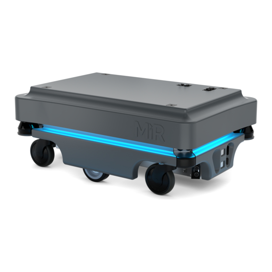
Page 20: Mir100™ Outer Parts
18. Rear skirt MiRCharge charging station 9. 3D depth camera 19. Charging port - behind the rear corner cover 10. Front laser scanner 20. Side skirt • • • MiR100™ User Guide, Robot Interface 2.0, 11/2017 v.1.0 • • •... -
Page 21: Mir200™ Inner Parts
12. 24/24 V switch mode power supply - provides power outage safety components. Ensures stable voltage 5. Redundant drive - relays controlled by SICK modules 13. 5V power supply - power to the MiR board supplying the motor controller 6. Router - local network 14. Loud speaker 7. -
Page 22: Sensor Systems
Product presentation 4.5 Sensor systems The MiR100™ has a number of internal and external safety sensors to secure safe operation among people and equipment. External sensors Internal sensors (see MiR100™ Outer parts on page 20) (see MiR100™ Outer parts on page 20 •... - Page 23 After creation of the map, positions and other features can be added in the map editor. • MiRHook A hook may be mounted on the MiR100™ enabling it to tow carts with a payload of up to 300 kg. • •...
-
Page 24: Accessories
• • • • • • 5.1 Overview The MiR100™ can be equipped with a range of applications to suit the specific purpose the robot will be used for. Some are user-provided and others are purchased directly from Mobile Industrial Robots. -
Page 25: Technical Specifications
520 mm around center of robot Positioning accuracy +/- 50 mm of position, +/- 10 mm to docking marker Traversable gap and sill tolerance 20 mm • • • MiR100™ User Guide, Robot Interface 2.0, 11/2017 v.1.0 • • •... - Page 26 EN 1525, PLd cat. 3, ESD approved and CE certified Top module Max height from floor to top 1800 mm Center of gravity Lower than 900 mm above the floor • • • MiR100™ User Guide, Robot Interface 2.0, 11/2017 v.1.0 • • •...
-
Page 27: Dimension Drawing
Technical specifications 6.2 Dimension drawing Figure 6.1. Dimensions of the MiR100™ • • • MiR100™ User Guide, Robot Interface 2.0, 11/2017 v.1.0 • • •... -
Page 28: Maintenance
The following maintenance schedules give an overview of regular cleaning and parts replacement procedures. The stated intervals are indicative and depend on the operating environment and frequency of usage of the robot. 7.1.1 Regular cleaning This table gives an overview of maintenance tasks for the MiR100™ Part Maintenance Interval Robot... - Page 29 Replace as needed. The robot must be calibrated after replacement of the wheels. Battery Check if it discharges to fast. Replace every two years or 1000 cycles • • • MiR100™ User Guide, Robot Interface 2.0, 11/2017 v.1.0 • • •...
-
Page 30: Troubleshooting
• Check that the wheels are unobstructed and not tangled up in anything. • Check that the status is OK: in the MiR user interface, go to Monitoring > Hardware Health. Tap to open the group Sensors and check that 3D Camera (Floor) is on. -
Page 31: Repacking For Transport
Contact your distributor for more information. 9.2 Packing the robot for transportation To pack the robot, reverse the steps of the unpacking procedure, see “Unpacking the MiR100™” on page 10. The robot must always be packed and transported in an upright position. Packing and transporting the robot in any other position will void the warranty. -
Page 32: Payload Specifications
The specifications apply to payloads of: • 25 kg • 50 kg • 75 kg • 100 kg 1400 1400 1200 1200 1000 1000 1000 1000 Units: mm 25kg payload • • • MiR100™ User Guide, Robot Interface 2.0, 11/2017 v.1.0 • • •... - Page 33 Payload specifications 1400 1400 1200 1200 1000 1000 1000 1000 Units: mm 50kg payload • • • MiR100™ User Guide, Robot Interface 2.0, 11/2017 v.1.0 • • •...
- Page 34 Payload specifications 1400 1400 1200 1200 1000 1000 1000 1000 Units: mm 75kg payload • • • MiR100™ User Guide, Robot Interface 2.0, 11/2017 v.1.0 • • •...
-
Page 35: Payload Specifications
Payload specifications 1400 1400 1200 1200 1000 1000 1000 1000 Units: mm 100kg payload • • • MiR100™ User Guide, Robot Interface 2.0, 11/2017 v.1.0 • • •... -
Page 36: Declaration Of Conformity
The user provides the destination of product delivery via a web interface. MiR100 can be set up to run a fixed route (Route), be called on demand (Taxi), or perform a more special operation (Mission). - Page 37 Declaration of conformity • • • MiR100™ User Guide, Robot Interface 2.0, 11/2017 v.1.0 • • •...
-
Page 38: Neutrik Connector
Signal name Max. current Remarks Battery voltage Always on Battery voltage Starts with the robot Battery voltage Stops by emergency stop Ground Figure C.1. Neutrik FC4 FDL1-B • • • MiR100™ User Guide, Robot Interface 2.0, 11/2017 v.1.0 • • •... - Page 39 Neutrik connector • • • MiR100™ User Guide, Robot Interface 2.0, 11/2017 v.1.0 • • •...
Need help?
Do you have a question about the MiR100 and is the answer not in the manual?
Questions and answers