
Related Manuals for Crestron Crestron Green Light DIN-HUB


Summary of Contents for Crestron Crestron Green Light DIN-HUB
- Page 1 Crestron Green Light™ DIN-HUB DIN Rail Cresnet Distribution Hub ® Operations & Installation Guide...
- Page 2 This document was prepared and written by the Technical Documentation department at: Crestron Electronics, Inc. 15 Volvo Drive Rockleigh, NJ 07647 1-888-CRESTRON All brand names, product names and trademarks are the property of their respective owners. ©2008 Crestron Electronics, Inc.
-
Page 3: Table Of Contents
Crestron DIN-HUB Contents Crestron Green Light™ DIN Rail Cresnet Introduction ... 1 Features and Functions ... 1 Applications... 3 Specifications ... 4 Physical Description... 5 Industry Compliance ... 8 Setup ... 9 Network Wiring... 9 Installation ... 9 Hardware Hookup ... 11 Problem Solving ... -
Page 5: Crestron Green Light™ Din Rail Cresnet Distribution Hub: Din-Hub
Crestron DIN-HUB Crestron Green Light™ DIN Rail ® Cresnet Distribution Hub: DIN-HUB Introduction The DIN-HUB is a DIN rail-mounted Cresnet the configuration of large Cresnet networks. DIN rail mounting enables modular installation alongside Crestron automation control modules and other third party DIN rail mountable devices. -
Page 6: Din Rail Installation
® DIN Rail Cresnet Distribution Hub Three-Segment Cresnet Hub Cresnet is the communications backbone for Crestron lighting modules, wall box dimmers, shade controllers, thermostats, keypads, touchpanels, and many other devices. This flexible 4-wire bus normally supports approximately 20 Cresnet devices without requiring a hub. Larger systems are easily enabled by adding the DIN-HUB. -
Page 7: Applications
Crestron DIN-HUB Applications The following diagram shows a DIN-HUB in a typical application. DIN-HUB in a Typical Application Operations & Installation Guide – DOC. 6671A ® DIN Rail Cresnet Distribution Hub DIN Rail Cresnet Hub: DIN-HUB • 3... -
Page 8: Specifications
® DIN Rail Cresnet Distribution Hub Specifications Specifications for the DIN-HUB are listed in the following table. DIN-HUB Specifications SPECIFICATION Power Requirements Cresnet Power Usage Maximum Load per Segment Environmental Temperature Humidity Heat Dissipation Enclosure Dimensions Height Width Depth Weight Available Accessories DIN-BLOCK DIN-PWS50... -
Page 9: Physical Description
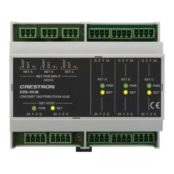
Crestron DIN-HUB Physical Description This section provides information on the connections, controls and indicators available on your DIN-HUB. DIN-HUB Physical View DIN-HUB Overall Dimensions 106 mm (4.17 in) Operations & Installation Guide – DOC. 6671A DIN Rail Cresnet 94.2 mm (3.71 in) 90 mm (3.54 in) - Page 10 ® DIN Rail Cresnet Distribution Hub Connectors, Controls & Indicators CONNECTORS CONTROLS & INDICATORS NET PWR INPUT NET HOST and LEDs (Continued on following page) 6 • DIN Rail Cresnet Hub: DIN-HUB (3) 3-pin 3.5 mm detachable (A/B/C) terminal blocks Cresnet power selection connectors for each segment Connect to external Cresnet...
- Page 11 Crestron DIN-HUB Connectors, Controls & Indicators (Continued) CONNECTORS CONTROLS & INDICATORS NET HOST and LEDs NET A/B/C and LEDs 1. Interface connectors for NET HOST, NET PWR INPUT, and NET ports are provided with the unit. 2. Y, Z, and G terminals are paralleled within each segment. Operations &...
-
Page 12: Industry Compliance
® DIN Rail Cresnet Distribution Hub Industry Compliance This unit has been manufactured to comply with UL’s Standards for Safety in Canada and the United States. Formal approval is pending. As of the date of manufacture, the DIN-HUB has been tested and found to comply with specifications for CE marking and standards per EMC and Radiocommunications Compliance Labelling. -
Page 13: Setup
Crestron DIN-HUB Setup Network Wiring When wiring the Cresnet • Use Crestron Certified Wire. NOTE: Cresnet-HP wire cannot be used. • Use Crestron power supplies for Crestron equipment. • Provide sufficient power to the system. CAUTION: Insufficient power can lead to unpredictable results or damage to the equipment. - Page 14 ® DIN Rail Cresnet Distribution Hub The DIN-HUB is designed for installation on a DIN rail. Refer to the following diagram when installing. Installing the DIN-HUB DIN RAIL RELEASE 1. Place the top of the DIN-HUB’s rail mount over the top of the DIN rail.
-
Page 15: Hardware Hookup
Crestron DIN-HUB Hardware Hookup Make the necessary connections as called out in the illustration that follows this paragraph. Refer to “Network Wiring” on page 9 before attaching the 4-position terminal block connector. Apply power after all connections have been made. When making connections to the DIN-HUB, use a Crestron power supply. - Page 16 ® DIN Rail Cresnet Distribution Hub Power can be supplied from a DIN-PWS50 DIN Rail Power Supply or other Cresnet power supply connected to the NET HOST port. For more information, refer to the latest version of the DIN-PWS50 Operations & Installation Guide (Doc.
-
Page 17: Problem Solving
Crestron DIN-HUB Problem Solving Troubleshooting The following table provides corrective action for possible trouble situations. If further assistance is required, please contact a Crestron customer service representative. DIN-HUB Troubleshooting TROUBLE NET HOST PWR LED does not illuminate. Segment’s NET LED does not illuminate. -
Page 18: Check Network Wiring
® DIN Rail Cresnet Distribution Hub DIN-HUB Troubleshooting (Continued) TROUBLE Segment’s PWR LED does not illuminate. Network not working and only one LED is illuminated. Check Network Wiring Use the Right In order to ensure optimum performance over the full range of your Wire installation topology, Crestron Certified Wire and only Crestron Certified Wire may be used. -
Page 19: Reference Documents
Crestron DIN-HUB Cresnet units are to be daisy-chained on the run, the Cresnet power usage of each network unit to be daisy-chained must be added together to determine the Cresnet power usage of the entire chain. If the unit is home-run from a Crestron system power supply network port, the Cresnet power usage of that unit is the Cresnet power usage of the entire run. -
Page 20: Document Title
® DIN Rail Cresnet Distribution Hub List of Related Reference Documents DIN-PWS50 DIN Rail 50 Watt Cresnet Power Supply Further Inquiries If you cannot locate specific information or have questions after reviewing this guide, please take advantage of Crestron's award winning customer service team by calling Crestron at 1-888-CRESTRON [1-888-273-7876]. -
Page 21: Return And Warranty Policies
Crestron DIN-HUB Return and Warranty Policies Merchandise Returns / Repair Service 1. No merchandise may be returned for credit, exchange or service without prior authorization from CRESTRON. To obtain warranty service for CRESTRON products, contact an authorized CRESTRON dealer. Only authorized CRESTRON dealers may contact the factory and request an RMA (Return Merchandise Authorization) number. - Page 22 ® DIN Rail Cresnet Distribution Hub Crestron DIN-HUB This page is intentionally left blank. 18 • DIN Rail Cresnet Hub: DIN-HUB Operations & Installation Guide – DOC. 6671A...
- Page 23 ® Crestron DIN-HUB DIN Rail Cresnet Distribution Hub This page is intentionally left blank. DIN Rail Cresnet Hub: DIN-HUB • 19 Operations & Installation Guide – DOC. 6671A...
- Page 24 Crestron Electronics, Inc. Operations & Installation Guide – DOC. 6671A 15 Volvo Drive Rockleigh, NJ 07647 (2020753) Tel: 888.CRESTRON 05.08 Fax: 201.767.7576 Specifications subject to www.crestron.com change without notice.
Need help?
Do you have a question about the Crestron Green Light DIN-HUB and is the answer not in the manual?
Questions and answers