Advertisement
Quick Links
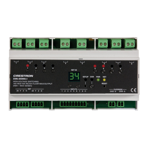
DIN-8SW8-I
DIN Rail High-Voltage Switch with Digital Inputs
Installation Guide
Description
The Crestron
®
DIN-8SW8-I is an 8-channel lighting control module designed to support
switching of non-dimmable lighting and fans. In addition, the DIN-8SW8-I features eight
isolated digital inputs, allowing standard momentary switches to trigger events with or
without a control system. A single model supports both 120 and 220−240 volt
applications. Each channel handles incandescent loads up to 10 amps, uorescent loads
up to 5 amps, and also 1/2 HP motors. The DIN-8SW8-I may not be compatible with
some high inrush current loads.
DIN-8SW8-I Speci cations
SPECIFICATION
DETAILS
Load Ratings
Switch Channels
8
Maximum per Channel
10 amps incandescent, 5 amps uorescent,
0.5 HP @ 120 to 240 volts ac, 50/60 Hz;
5 amps @ 30 volts dc;
16 amps resistive
Module Total
80 amps incandescent, 40 amps uorescent @
120–240 volts ac, 50/60 Hz
Load Types
Incandescent, Magnetic Low-Voltage, Electronic
Low-Voltage, Neon/Cold Cathode, Fluorescent,
Motors
NOTE: May not be compatible with some high
inrush current loads.
Environmental
Temperature
32° to 104°F (0° to 40°C)
Humidity
10% to 90% RH (noncondensing)
Heat Dissipation
18 Btu/h
Weight
14 oz (369 g)
Additional Resources
Visit the product page on the Crestron website (www.crestron.com)
for additional information and the latest rmware updates. Use a QR
reader application on your mobile device to scan the QR image.
Installation
WARNING: To avoid re, shock, or death, turn off the power at the circuit breaker or
fuse and test that power is off before wiring!
CAUTION: This equipment is for indoor use only. Mount in a well-ventilated area. The
ambient temperature must be 32º to 104ºF (0º to 40ºC). The relative humidity must be
10% to 90% (non-condensing).
NOTES: Observe the following points:
• When installing in an enclosure, group high-voltage devices separately from
low-voltage devices.
• Install and use this product in accordance with appropriate electrical codes and
regulations.
• A licensed electrician must install this product.
The DIN-8SW8-I is designed for installation on a DIN rail. Refer to the following diagram
when installing.
Installing the DIN-8SW8-I
DIN-8SW8-I
Top
DIN Rail
Release
Install the DIN-8SW8-I.
1. Place the top of the DIN-8SW8-I's rail mount over the top of the DIN rail.
2. Tilt the bottom of the DIN-8SW8-I toward the DIN rail until it snaps into place.
NOTE: It may be necessary to use a at-head screwdriver to pull the DIN rail release
tab while snapping the device onto the DIN rail.
To remove the DIN-8SW8-I from the DIN rail, use a small, at object (i.e., a at-head
screwdriver) to pull the DIN rail release, and tilt the bottom of the DIN-8SW8-I away from
the DIN rail.
NOTE: Certain third-party DIN cabinets provide space for an informational label
between each DIN rail row. Crestron's Engraver software (version 4.0 or later) can
generate appropriate labels for all Crestron DIN rail products.
Hardware Hookup
Make the necessary connections. Apply power after all connections have been made.
WARNING: Prior to connecting the device, turn off the power at the circuit breaker.
Failure to do so may result in serious personal injury or damage to the device. Restore
the power after all connections have been made.
CAUTION: Connecting this device to the wrong type of load or short-circuiting the
load can cause severe product damage. Test each load to identify a short-circuit
condition prior to wiring the load to the module.
NOTE: Install in accordance with all local and national electric codes.
NOTE: High-voltage connections accept 12 AWG (2.5 mm
stripped to 1/3 inch (8 mm). Tighten terminal blocks to 5 in-lbs (0.5 Nm).
NOTE: Use copper wire only. For high-voltage connections, use wire rated for at least
75ºC.
NOTE: Each switch leg of the DIN-8SW8-I may be fed from a separate circuit breaker.
When making Cresnet
®
(NET), INPUTS, and OVERRIDE connections, strip the ends of
the wires approximately 1/4 in (6 mm). Use care to avoid nicking the conductors. Twist
together the ends of the wires that share a connection. Apply solder only to the ends of
the twisted wires. Avoid tinning too far up the wires, or the end becomes brittle.
When making power connections to the DIN-8SW8-I, use a Crestron power supply.
Hardware Connections for the DIN-8SW8-I
DIN Rail
1 to 8:
(Not Supplied)
Connections for
Controlled Devices
NET:
To Control System and
Other Cresnet Devices
INPUTS:
Connections from
Switches and Other
Control Devices
With the circuit breaker turned off, connect the wires to the terminal blocks per the
markings provided on the DIN-8SW8-I.
Load Connection Example for the DIN-8SW8-I
Neutral
120/240 Volts
Line
From Breaker
2
) wire. Wire should be
Power Supply Connections (Using an Isolated Power Supply)
INPUTS
1 2 3 4 5 6 7 8 C
Momentary
Switches
12 to 24 V
Power
Supply
Power Supply Connections (Using Existing Cresnet Power)
Z G
24
Y
OVERRIDE:
From Device Providing Override
Signal and to Other Devices
Receiving Override Signal
24 V
Cresnet
Power
Supply
120/240 Volts
Load
INPUTS
1 2 3 4 5 6 7 8 C
Momentary
Switches
Advertisement

Related Manuals for Crestron DIN-8SW8-I


Summary of Contents for Crestron DIN-8SW8-I
- Page 1 32º to 104ºF (0º to 40ºC). The relative humidity must be applications. Each channel handles incandescent loads up to 10 amps, uorescent loads up to 5 amps, and also 1/2 HP motors. The DIN-8SW8-I may not be compatible with 10% to 90% (non-condensing).
- Page 2 Set the Net ID Troubleshooting The Net ID of the DIN-8SW8-I has been factory set to 89. The Net IDs of all devices in The following table provides corrective action for possible trouble situations. If further the same system must be unique. The Net ID can be changed from the front panel of the assistance is required, please contact a Crestron customer service representative.
Need help?
Do you have a question about the DIN-8SW8-I and is the answer not in the manual?
Questions and answers