
Related Manuals for Ruijie RG-AP180(V3)


Summary of Contents for Ruijie RG-AP180(V3)
- Page 1 Ruijie RG-AP180(V3) Access Point Hardware Installation and Reference Guide Document Version: V1.3 Date: August 16, 2023 Copyright © 2023 Ruijie Networks...
- Page 2 Due to product version upgrades or other reasons, the content of this document will be updated from time to time. Ruijie Networks reserves the right to modify the content of the document without any notice or prompt.
-
Page 3: Preface
Preface Intended Audience This document is intended for: Network engineers Technical support and servicing engineers Network administrators Technical Support Ruijie Networks Website: https://www.ruijienetworks.com/ Technical Support Website: https://ruijienetworks.com/support Case Portal: https://caseportal.ruijienetworks.com Community: https://community.ruijienetworks.com Technical Support Email: service_rj@ruijienetworks.com... - Page 4 Specification An alert that contains a description of product or version support. 2. Note The manual offers configuration information (including model, port type and command line interface) for indicative purpose only. In case of any discrepancy or inconsistency between the manual and the actual version, the actual version prevails.
-
Page 5: Table Of Contents
Contents Preface ..............................I 1 Product Introduction ........................1 1.1 Overview ........................... 1 1.2 Product Appearance ........................ 1 1.3 Package Contents ........................4 1.4 Technical Specifications ......................5 1.4.1 Dimensions and Weight....................5 1.4.2 Radio Specifications ..................... 5 1.4.3 Port Specifications ......................7 1.4.4 Power Supply and Consumption ................ - Page 6 2.2.2 Ventilation Requirements ..................13 2.2.3 Space Requirements ....................13 2.2.4 Temperature/Humidity Requirements ..............13 2.2.5 Cleanliness Requirements ..................14 2.2.6 Anti-interference Requirements ................15 2.2.7 Installation Site Requirements .................. 15 2.3 Tools ............................16 3 Installation ............................. 17 3.1 Installation Procedure ......................17 3.2 Before You Begin ........................
- Page 7 3.7.3 Checking the Power Supply ..................24 4 Verifying the Operating Status ..................... 25 4.1 Establishing the Configuration Environment ..............25 4.2 Powering on the AP ........................ 25 4.2.1 Checklist Before Power-on ..................25 4.2.2 Checking the Environment after Power-on ............. 25 5 Monitoring and Maintenance .......................
- Page 8 6.2.7 The Wireless Signal Cannot Be Found ..............29 7 Appendix ............................30 7.1 Connectors and Media ......................30 7.2 Cabling Recommendations in Installation ................32 7.3 DC Connector Specifications ....................37...
-
Page 9: Product Introduction
Product Introduction Product Introduction Overview The RG-AP180(V3) is a dual-band 802.11ax-compliant access point (AP) released by Ruijie Networks for indoor scenarios in the general education, higher education, hotel, office and dormitory. With simple and beautiful appearance design, the RG-AP180(V3) can be deployed without damaging the wall decoration. - Page 10 Hardware Installation and Reference Guide Product Introduction Figure 1-1 Front View Figure 1-2 Left Side View...
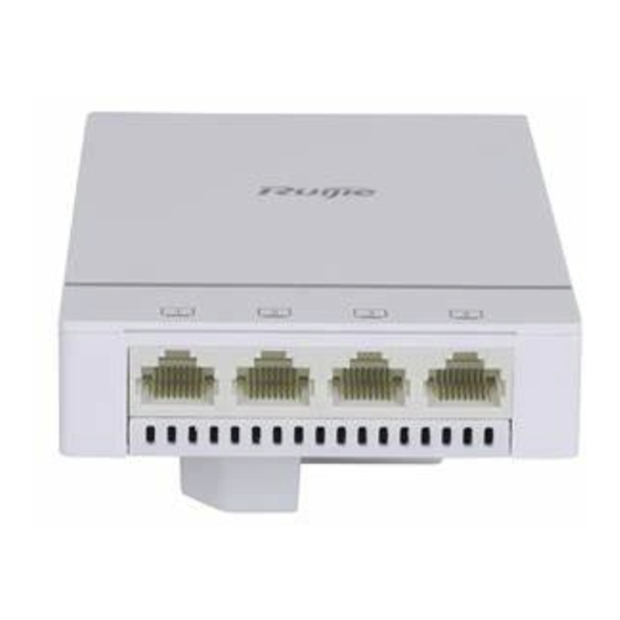
- Page 11 Hardware Installation and Reference Guide Product Introduction Table 1-1 Port Description Item Description Console port Connected with a serial port cable for device management 2–5 LAN port Downlink service port for data transmission Figure 1-3 Right Side View Table 1-2 Button and Port Description Item Description...
-
Page 12: Package Contents
Hardware Installation and Reference Guide Product Introduction Figure 1-4 Rear View Table 1-3 Port Description Item Description Uplink service port for data transmission, supporting IEEE WAN/PoE port 802.3af/at-compliant PoE Package Contents Table 1-4 Package Contents Item Quantity RG-AP180(V3) (including the white decorative cover) User manual... -
Page 13: Technical Specifications
Hardware Installation and Reference Guide Product Introduction Item Quantity Warranty card M4 x 40 Phillips pan head screws Technical Specifications 1.4.1 Dimensions and Weight Table 1-5 Dimensions and Weight Dimensions and RG-AP180(V3) Weight Dimensions (W x D x 86 mm x 116 mm x 24.1 mm (part outside the wall) + 18.9 mm (part inside the wall) (3.39 in. - Page 14 Hardware Installation and Reference Guide Product Introduction Radio Specifications RG-AP180(V3) Radio 1: 802.11b/g/n/ax, 2.400 GHz to 2.4835 GHz Radio 2: 802.11a/n/ac/ax, 5.150 GHz to 5.350 GHz, 5.470 GHz to Operating frequencies 5.725 GHz, 5.725 GHz to 5.850 GHz (Note: Country-specific restrictions apply.) Radio 1: 2.4 GHz, 574 Mbps Radio 2: 5 GHz, 2.402 Gbps Data rate...
-
Page 15: Port Specifications
Hardware Installation and Reference Guide Product Introduction Radio Specifications RG-AP180(V3) 802.11ac HT40: –82 dBm (MCS0), –57 dBm (MCS9) 802.11ac HT80: –79 dBm (MCS0), –53 dBm (MCS9) 802.11ax HE80: –79 dBm (MCS0), –52 dBm (MCS11) 802.11ax HE160: –75 dBm (MCS0), –47 dBm (MCS11) 1.4.3 Port Specifications Table 1-7... -
Page 16: Environment And Reliability
Hardware Installation and Reference Guide Product Introduction Power Supply and RG-AP180(V3) Consumption Max. power < 10 W consumption Caution To power the AP by using PoE, ensure that the device at the other end of the Ethernet cable supports IEEE 802.3af power supply. The AP adopts a fanless design. -
Page 17: Led And Button
Hardware Installation and Reference Guide Product Introduction LED and Button Note The LED description applies to both fit and fat modes unless otherwise specified. Table 1-10 LED Status Status Frequency Description The AP is not powered on. The AP is powered on, but the LED is turned off by software. - Page 18 Hardware Installation and Reference Guide Product Introduction Button Operation Result for less than 2s Press and hold the button for Restore to factory settings. longer than 5s...
-
Page 19: Preparing For Installation
Hardware Installation and Reference Guide Preparing for Installation Preparing for Installation Safety Precautions Note To avoid personal injury and device damage, carefully read the safety precautions before you install the device. The following safety precautions do not cover all possible dangers. ... -
Page 20: Electric Safety
Hardware Installation and Reference Guide Preparing for Installation 2.1.3 Electric Safety Warning Any nonstandard and inaccurate electric operation may cause an accident such as fire or electrical shock, thus causing severe even fatal damages to human bodies and the device. Direct or indirect touch through a wet object on high-voltage and mains supply may ... -
Page 21: Installation Environment Requirements
Hardware Installation and Reference Guide Preparing for Installation Installation Environment Requirements Install the device indoors to ensure its normal operation and prolong its service life. The installation site must meet the following requirements. 2.2.1 Bearing Requirements Evaluate the weight of the device and its accessories (such as the power supply module). Ensure that the installation site meets the requirements. -
Page 22: Cleanliness Requirements
Hardware Installation and Reference Guide Preparing for Installation Note The ambient temperature and humidity of the device are measured at the point that is 1.5 m (4.92 ft) above the floor and 0.4 m (1.31 ft.) before the device when there is no protective plate in front or at the back of the device. -
Page 23: Anti-Interference Requirements
Hardware Installation and Reference Guide Preparing for Installation Table 2-2 Requirements for Harmful Gases in the Equipment Room Average (mg/m Maximum (mg/m Sulfur dioxide (SO Hydrogen sulfide (H 0.006 0.03 Nitrogen dioxide (NO 0.04 0.15 Ammonia gas (NH 0.05 0.15 Chlorine gas (CI 0.01 Note... -
Page 24: Tools
Hardware Installation and Reference Guide Preparing for Installation Tools Table 2-3 Tools Common Phillips screwdriver, cables, fastening bolts, diagonal pliers, and flathead Tools screwdriver (used to remove the decorative cover) Special Wire stripper, crimping pliers, crystal connector crimping pliers, wire Tools cutter, and ESD tools Meter... -
Page 25: Installation
Hardware Installation and Reference Guide Installation Installation The RG-AP180(V3) must be installed and work indoors. Caution Before installing the AP, make sure that you have carefully read the requirements in Chapter 2. Installation Procedure Figure 3-1 shows the installation steps. Figure 3-1 Installation Procedure Start... -
Page 26: Before You Begin
Hardware Installation and Reference Guide Installation Before You Begin Carefully plan and arrange the installation location, networking mode, power supply, and cabling before installing the device. Confirm the following requirements before installation: The installation site provides sufficient space for proper ventilation. ... -
Page 27: Installing The Device
Hardware Installation and Reference Guide Installation Installing the Device Caution If you use an electric screwdriver for installation, the recommended torque for screw locking is 10 kgf-cm ± 1 kgf-cm (8.68 lbf-in ± 0.87 lbf-in). 3.4.1 86 mm Junction Box Installation (1) Use a screwdriver to disassemble the panel of the 86 mm junction box on the wall. - Page 28 Hardware Installation and Reference Guide Installation Figure 3-3 Connecting the Data Cable (3) Align the screw holes on the left and right sides of the AP with the screw holes in the 86 mm junction box with the Ethernet ports facing down, and use a screwdriver and the screws delivered with the AP to secure the AP.
- Page 29 Hardware Installation and Reference Guide Installation (4) Secure the decorative cover with the port number facing down and Ruijie logo facing Figure 3-5 Securing the Decorative Cover (5) Figure 3-6 figure shows the AP after the decorative cover is installed.
-
Page 30: Removing The Ap
Hardware Installation and Reference Guide Installation Caution When installing or moving the AP, ensure that the power supply is cut off. Ensure that the screws are tightened. Ensure that the AP is installed in a position where the LEDs can be easily observed. ... -
Page 31: Bundling Cables
Hardware Installation and Reference Guide Installation Caution By default, the baud rate is set to 9600, data bit to 8, stop bit to 1, with no parity check and no flow control on the console port of the AP. The console port is used only when you want to configure the AP manually. -
Page 32: Checking The Power Supply
Hardware Installation and Reference Guide Installation 3.7.3 Checking the Power Supply Verify that the power cord is properly connected and compliant with safety requirements. Turn on the power supply to power the AP. Verify that the AP works properly. ... -
Page 33: Verifying The Operating Status
Hardware Installation and Reference Guide Verifying the Operating Status Verifying the Operating Status Establishing the Configuration Environment Use DC power supply or PoE to power the AP. Confirm the following requirements before establishing the configuration environment: Verify that the AP is properly connected to the DC or PoE power supply and compliant ... -
Page 34: Monitoring And Maintenance
If the AP works in fat mode, you can log in to the AP remotely for maintenance. If the AP works in fit mode, you can use an AC to remotely manage and maintain the Hardware Maintenance If the hardware is faulty, contact Ruijie technical support. -
Page 35: Troubleshooting
Check whether the device is installed properly. Check whether the power supply is properly connected. Check whether the LEDs are normal. Check whether cables are properly connected to ports. Contact Ruijie technical support to check whether hardware faults exist. -
Page 36: Common Troubleshooting Procedures
Hardware Installation and Reference Guide Troubleshooting Common Troubleshooting Procedures 6.2.1 The Ethernet Port Does Not Work After the Ethernet Cable Is Plugged in Verify that the device at the other end of the Ethernet cable is working properly. And then verify that the Ethernet cable is capable of providing the required data rate and is properly connected. -
Page 37: The Led Keeps Blinking Red At An Interval Of 1S For A Long Time
Hardware Installation and Reference Guide Troubleshooting 6.2.6 The LED Keeps Blinking Red at an Interval of 1s for a Long Time If the LED keeps blinking red at an interval of 1s after the system starts, the AP probably has not established a proper CAPWAP connection with the AC. Verify that the AC works and the network is configured properly. -
Page 38: Appendix
Hardware Installation and Reference Guide Appendix Appendix Connectors and Media 1000BASE-T/100BASE-TX/10BASE-T Port The 1000BASE-T/100BASE-TX/10BASE-T is a 10/100/1000 Mbps port with auto- negotiation, which supports auto MDI/MDIX Crossover at these three rates. The 1000BASE-T complies with IEEE 802.3ab standard, and uses up to 100 m (328.08 ft) of 100-ohm CAT5, CAT 5e or twisted pairs with higher standard. - Page 39 Hardware Installation and Reference Guide Appendix Table 7-2 Pinouts of the 100BASE-TX/10BASE-T Socket Plug Input Receive Data+ Output Transmit Data+ Input Receive Data- Output Transmit Data- Output Transmit Data+ Input Receive Data+ Output Transmit Data- Input Receive Data- 4, 5, 7, 8 Not Used Not Used Table 7-3 lists the straight-through and crossover cable connections for the 100BASE-...
-
Page 40: Cabling Recommendations In Installation
Hardware Installation and Reference Guide Appendix Cabling Recommendations in Installation During installation, cables are tied in the binding rack on the cabinet by the cabling rack, and top or bottom cabling is adopted according to the actual situation in the equipment room. - Page 41 Hardware Installation and Reference Guide Appendix Figure 7-1 Bundling Cables (1) Cables of different types (such as power cords, signal cables, and ground cables) ○ should be separated in cabling and bundling. When they are close, crossover cabling can be adopted. In the case of parallel cabling, maintain a space of at least 30 mm (1.18 in.) for power cords and signal cables.
- Page 42 Hardware Installation and Reference Guide Appendix Figure 7-2 Bundling Cables (2) When cables need to bend, first bundle them up. However, the buckle cannot be ○ bundled within the bending area. Otherwise, significant stress may be generated in cables, breaking cable cores. Figure 7-3 Bundling Cables (3) Cables not to be assembled or remaining parts of cables should be folded and...
- Page 43 Hardware Installation and Reference Guide Appendix reserved for access after being assembled. When the moving part reaches the installation position, the remaining part should not touch heat sources, sharp corners, or sharp edges. If heat sources cannot be avoided, high-temperature cables should be used.
- Page 44 Hardware Installation and Reference Guide Appendix Table 7-4 Cable Bunch Distance Between Every Binding Cable Bunch Diameter (mm) Point (mm) 10 mm (0.39 in.) 80 mm to 150 mm (3.15 in. to 5.91 in.) 10 mm to 30 mm (0.39 in. to 1.18 in.) 150 mm to 200 mm (5.91 in.
-
Page 45: Dc Connector Specifications
Hardware Installation and Reference Guide Appendix DC Connector Specifications Input voltage: 12 V DC, rated current: 1 A Table 7-5 Technical Specifications of the DC Power Connector Inner Diameter Outer Diameter Depth Polarity 2.1 mm (0.08 in.) 5.5 mm (0.22 in.) 10 mm (0.39 in.) Center positive Figure 7-5...
Need help?
Do you have a question about the RG-AP180(V3) and is the answer not in the manual?
Questions and answers