Table of Contents
Advertisement
Quick Links
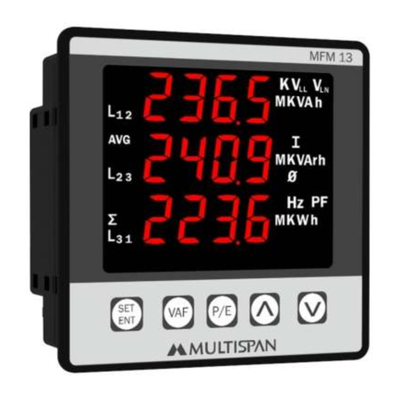
MULTI FUNCTION METER
MFM - 13
TECHNICAL SPECIFICATION
PARAMETER SPECIFICATION
Input Signal
3Ø 3 Wire / 3Ø 4Wire / 1Ø 2Wire
CT Primary
up to 6000A (Programmable)
5 Amp/1 Amp selectable
CT Secondary
PT Primary
100V to 520kV (Programmable)
PT Secondary
100V to 520V (L-L) (Programmable)
PF Avg. & Per Phase
0.100 - 1.000
Frequency (Hz)
45.00 - 60.00 Hz
Load hours
9999.59 Hrs/Min.
No load hours
9999.59 Hrs/Min.
RPM
3600 RPM @ 60 Hz & 2 pole
POWER
KW Total
0.000 - 9999 MW
kW Per Phase
0.000 - 9999 MW
kVA Total
0.000 - 9999 MVA
kVA Per Phase
0.000 - 9999 MVA
kVAr Total
0.000 - 9999 MVAr
kVAr Per Phase
0.000 - 9999 MVAr
ENERGY
kWH Total
000.000 - 999999999.999 kWh
kVAh Total
000.000 - 999999999.999 kVAh
kVArh Total
000.000 - 999999999.999 kVArh
DISPLAY & KEY :
Display
4 Digit,3 Line 0.57" RED
Key
SET/ENT,VAF,P/E, INC, DEC
DIMENSION :
Size
96 (H) x 96 (W) x 54 (D) mm
Panel Cutout
92 (H) x 92 (W) mm
PARAMETER SETTING
Long Press
key
Enter Password 10
PRG
Network Selection
/
/
PRG
CT Primary
(5 Amp to 6000 Amp selectable)
PRG
CT Secondary
/
(5 Amp/1 Amp selectable)
PRG
PT Primary
(100V to 520kV selectable)
PRG
PT Secondary
(100V to 520V selectable)
PRG
Mode selection
/
(Basic / Advance)
Press
key to save & exit from
PRG
parameter setting
AUXILIARY SUPPLY :
Supply voltage
12V - 60V DC
ACCURACY:
Class 0.5 (Standard)
ENVIRONMENT CONDITION:
Operating Temp.
0°C to 55°C
UP to 95% RH
Relative Humidity
(non-condensing)
Protection Level
IP-65 (Front side) As per IS/IEC
(AS Per Request)
60529 : 2001
MECHANICAL INSTALLATION
Panel Cutout
Outline Dimension (mm)
Dimension (mm)
MFM 13
L L
92
96
SET
VAF
P/E
ENT
92
3
96
54
TERMINAL CONNECTION
20
19
18
17
16
15
14 13
L1
L2
L3
S1
S2
S1
S2
S1
S2
Current: 30mA To 5A AC
Voltage (L-L) : 35-600V AC
(L-N) : 20-350V AC
CAT III
Primary PT : 100V to 520KV
Secondary PT : 100V to 520V
Primary CT: Up to 6000A AC
Made in India
Secondary CT: By 5A/1A AC
12V 60V
!
System: 1Ph-2W/3Ph-3W/3Ph-4W
DC
Accuracy Class: 0.5
www.multispanindia.com
V
V
V
-
+
L
L
1
2
1
2
3
4
5
6
7
8
VAF Pages :
Press
key to change page
VAF
1) Voltage L-N
L N
2) Voltage L-L
L L
3) Current
4) System Frequency
5) AVG V(L-N)-A-F
L N
Note : In 3P-3W Page 2,3,4,6,8,10 will display
KEY OPERATION
FUNCTION
OPERATOR MODE
To view VAF Pages
To view Power & Energy Pages
To scroll & hold pages
PARAMETER SETTING MODE
To Set Parameter Value
To Increment parameter value
To Decrement parameter value
To Exit from parameter setting
Resolution
PT Ratio x CT Ratio
<15
<150
<1500
<15000
<150000
12
11
>150000
+
-
Pulse
O/P
INSTALLATION GUIDELINES
1. This equipment, being built-in-type, normally becomes a
part of main control panel and in such case the terminals
do not remain accessible to the end user after installation
and internal wiring.
2. Do not allow pieces of metal, wire clippings, or fine metallic
N
L
fillings from installation to enter the product or else it may
3
lead to a safety hazard that may in turn endanger life or
9
10
cause electrical shock to the operator.
3. Circuit breaker or mains switch must be installed between
power source and supply terminal to facilitate power 'ON' or
'OFF' function. However this mains switch or circuit breaker
must be installed at convenient place normally accessible to
the operator.
4. Use and store the instrument within the specified ambient
temperature and humidity ranges as mentioned in this
manual.
BASIC MODE PAGES
6) AVG V(L-L)-A-F
L L
7) PF L1L2L3
8) System PF
9) AVG V(L-N)-A-PF
L N
10) AVG V(L-L)-A-PF
L L
1) V(L-N)-A-F
4) kWh Total
MECHANICAL INSTALLATION GUIDELINES
1. Prepare the panel cutout with proper dimensions as shown
PRESS KEY
above.
2. Fit the unit into the panel with the help of clamp given.
VAF
3. The equipment in its installed state must not come in close
proximity to any heating source, caustic vapors, oils steam,
or other unwanted process byproducts.
P/E
4. Use the specified size of crimp terminal (M3.5 screws) to
wire the terminal block. Tightening the screws on the
terminal block using the tightening torque of the range of
Press
For
+
1.2 N.m.
5Sec
5. Do not connect anything to unused terminals.
MAINTENANCE
Press
For 5 Sec
1. The equipment should be cleaned regularly to avoid
blockage of ventilating parts.
2. Clean the equipment with a clean soft cloth. Do not use
isopropyl alcohol or any other cleaning agent.
3. Fusible resistor must not be replaced by operator.
SAFETY PRECAUTION
!
All safety related codifications, symbols and instructions
that appear in this operating manual or on the equipment
must be strictly followed to ensure the safety of the operating
personnel as well as the instrument.
Pulse/Kwh
If all the equipment is not handled in a manner specified
0.01Kwh
by the manufacturer, it might impair the protection provided
0.1Kwh
by the equipment.
1Kwh
Read complete instructions prior to installation
10Kwh
and operation of the unit.
100Kwh
1000Kwh
WARNING : Risk of electric shock.
WARNING GUIDELINES
WARNING : Risk of electric shock.
1. To prevent the risk of electric shock, power supply to the
equipment must be kept OFF while doing the wiring
arrangement. Do not touch the terminals while power is
being supplied.
2. To reduce electro magnetic interference, use wire with
adequate rating and twists of the same of equal size shall
be made with shortest connection.
3. Cable used for connection to power source, must have a
cross section of 1mm or greater. These wires should have
insulations capacity made of at least 1.5kV.
4. A better anti-noise effect can be expected by using
standard power supply cable for the instrument.
POWER & ENERGY Pages :
Press
key to change page
P/E
1) kW PER PHASE
5) kWh Total
2) kVA PER PHASE
6) kvah Total
3) kvar PER PHASE
7) kvarh Total
4) TOTAL kVA,kvar,kW
Note : In 3P-3W
Page 4,5,6,7 will display
1Phase 2 wire Pages
2) V(L-N)-A-PF
3) TOTAL kVA,kvar,kW
L N
L N
5) kvah Total
6) kvarh Total
Advertisement
Table of Contents

Related Manuals for MULTISPAN MFM13


Summary of Contents for MULTISPAN MFM13
- Page 1 MULTI FUNCTION METER AUXILIARY SUPPLY : MECHANICAL INSTALLATION GUIDELINES KEY OPERATION MFM - 13 Supply voltage 12V - 60V DC 1. Prepare the panel cutout with proper dimensions as shown FUNCTION PRESS KEY ACCURACY: above. OPERATOR MODE 2. Fit the unit into the panel with the help of clamp given. Class 0.5 (Standard) To view VAF Pages 3.
- Page 2 ADVANCE MODE PAGES LOAD HOUR & RPM POWER & ENERGY Pages : VAF Pages : Enter Password 25 Press key to change page Press key to change page 1) kW PER PHASE 8) kWh Total Load Hour 1) Voltage L-N 13) PF L1 L2 L3 Enable / Disable Load Hour...
Need help?
Do you have a question about the MFM13 and is the answer not in the manual?
Questions and answers