Table of Contents
Advertisement
Quick Links
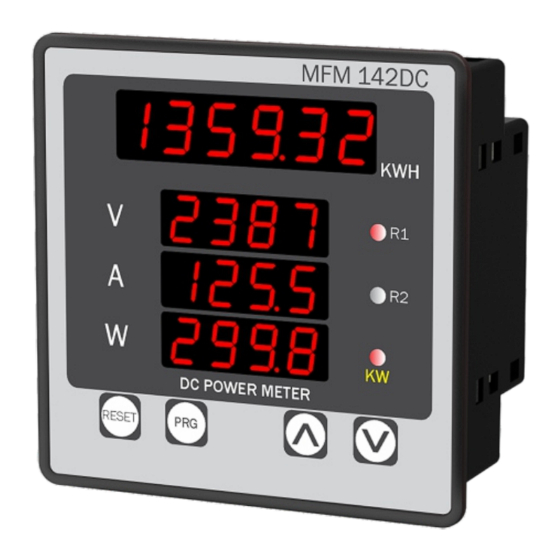
DC MULTIFUNCTION METER
MFM 142DC
TECHNICAL SPECIFICATION
INPUT SPECIFICATION :
Current
Input Current
Through external shunt
(-75mV To+75mV DC)
Shunt Selectable
0 to 9999 Amp
Voltage
Direct voltage DC
0 to 1000V DC
CALCULATED PARAMETERS :
Parameter
Range
Accuracy
0.00 - 49.99 V DC
1 % OF 49.99V
50.0 - 199.9 V DC
1 % OF 199.9V
DC Voltage
200.0 - 399.9 V DC
1 % OF 399.9V
400.0 - 1000 V DC
1 % OF 1000 V
DC Current
-999 - 9999 A DC
1 % OF FSD
WATT
-999 - 9999 KW
0 - 999999 KWH
KWH
DISPLAY & KEYS :
6 Digit, 7 seg. 0.40" RED
Display
4 Digit, 3 Line 7 seg. 0.40" RED
Key
RESET, PRG, INC, DEC
DIMENSION :
Size (mm)
96 (H) x 96 (W) x 54 (D) mm
Panel Cutout
92 (H) x 92 (W) mm
AUXILIARY POWER SUPPLY :
Power Supply
100V to 270V AC
Burden
Approx 5VA @ 230V AC
OUTPUT SPECIFICATION:
Relay Output
Relay
2 Nos
Relay Type
1C/O (NO-C-NC)
Rating
10A, 230V AC / 28V DC (Reg. Load)
ACCURACY
Class 1.0 (Standard)
ENVIRONMENTAL CONDITION
0 to 55°C
Working Temperature
Storage Temperature
0 to 55°C
Relative Humidity
95 % RH Non-
Condensing
IP-65 (Front side As per
Protection Level
( As per Request )
IS/IEC 60529 : 2001)
MECHANICAL INSTALLATION
Outline Dimension (mm)
Panel Cutout
Dimension (mm)
MFM 142DC
R1
92
96
R2
DC POWER METER
RESET
PRG
92
3
96
54
TERMINAL CONNECTION
20
19
18
17
16
15
14 13
12
NC
C
NO
NC
C
NO
RELAY-2
RELAY-1
+1000V DC
www.multispanindia.com
Made in India
GND
100
~
Voltage: 0 To 1000V DC
270V AC
Current: -999 To 9999 Amp DC
50/60 HZ
(Through Shunt)
5VA
Input: -75 To 75mV
Accuracy: Class 1.0
N
L
1
2
3
4
5
6
7
8
DISPLAY INDICATION
KWH Value
DC Volt
DC Amp
DC Watt
DC POWER METER
KEY OPERATION
FUNCTION
OPERATOR MODE
To enter in parameter setting
To Reset the KWH Value
Parameter Setting MODE
To set parameter value
To increment parameter value.
To decrement parameter value.
Set parameter to be save & exit.
MECHANICAL INSTALLATION
1. Prepare the panel cutout with proper dimensions as shown
above.
2. Fit the unit into the panel with the help of clamp given.
11
3. The equipment in its installed state must not come in close
proximity to any heating source, caustic vapors, oil steam,
or other unwanted process byproducts.
4. Use the specified size of crimp terminal (M3.5 screws) to
wire the terminal block. Tightening the screws on the
terminal block using the tightening torque of the range of
1.2 N.m.
5. Do not connect anything to unused terminals.
MAINTENANCE
MAINTENANCE
9
10
1. The equipment should be cleaned regularly to avoid
blockage of ventilating parts.
2. Clean the equipment with a clean soft cloth. Do not use
isopropyl alcohol or any other cleaning agent.
3. Fusible resistor must not be replaced by operator.
SAFETY PRECAUTION
!
Please read the "Safety Warnings" in the instruction
manual supplied with the instrument thoroughly and
completely for correct use. Failure to follow the safety rules
can cause fire, trouble, electrical shock, etc. Therefore, make
sure to operate the instrument on a correct power supply
Relay For
and voltage rating marked on each
R1
Over Voltage
& Under Voltage
If all the equipment is not handled in a manner specified
Tripping
R2
by the manufacturer, it might impair the protection provided
by the equipment.
Read complete instructions prior to installation
and operation of the unit.
WARNING : Risk of electric shock.
PRESS KEY
WARNING GUIDELINES
Press
WARNING : Risk of electric shock.
PRG
5 sec
1) To prevent the risk of electric shock, power supply to the
RESET
equipment must be kept OFF while doing the wiring
arrangement. Do not touch the terminals while power is
being supplied.
2) To reduce electro magnetic interference, use wire with
PRG
adequate rating and twists of the same of equal size shall
be made with shortest connection.
3. Cable used for connection to power source, must have a
cross section of 1mm or greater. These wires should have
insulations capacity made of at least 1.5kV.
4) A better anti-noise effect can be expected by using
PRG
standard power supply cable for the instrument.
INSTALLATION GUIDELINES
1) Do not allow pieces of metal, wire clippings, or fine
metallic fillings from installation to enter the product or
else it may lead to a safety hazard that may in turn
endanger life or cause electrical shock to the operator.
2) Circuit breaker or mains switch must be installed
between power source and supply terminal to facilitate
power 'ON' or 'OFF' function. However this mains switch
or circuit breaker must be installed at convenient place
normally accessible to the operator.
3) Use and store the instrument within the specified ambient
temperature and humidity ranges as mentioned in this
manual.
instrument.
Page 1
Page 1
Advertisement
Table of Contents

Related Manuals for MULTISPAN MFM 142DC


Summary of Contents for MULTISPAN MFM 142DC
- Page 1 DC MULTIFUNCTION METER DISPLAY INDICATION SAFETY PRECAUTION OUTPUT SPECIFICATION: MFM 142DC Relay Output Please read the "Safety Warnings" in the instruction Relay 2 Nos manual supplied with the instrument thoroughly and KWH Value completely for correct use. Failure to follow the safety rules...
- Page 2 KWH RESET PARAMETER SETTING To Reset KWH Press Key For 5 Sec Press RESET HYS1 Press Key For 5 Sec. To Enter in Parameter Setting PASSWD Hystersis PASSWD Password Selectable Password (15) 0 To 100V (10) Press Press SET2 Press Set Point 2 RESET For Relay 2...
Need help?
Do you have a question about the MFM 142DC and is the answer not in the manual?
Questions and answers