Table of Contents
Advertisement
Quick Links
Advertisement
Table of Contents

Related Manuals for Juniper MX2008


Summary of Contents for Juniper MX2008
- Page 1 MX2008 Universal Routing Platform Hardware Guide Published 2020-03-20...
- Page 2 END USER LICENSE AGREEMENT The Juniper Networks product that is the subject of this technical documentation consists of (or is intended for use with) Juniper Networks software. Use of such software is subject to the terms and conditions of the End User License Agreement (“EULA”) posted at https://support.juniper.net/support/eula/.
-
Page 3: Table Of Contents
MX2008 Alarm LEDs and Alarm Cutoff/Lamp Test Button | 45 MX2008 Component LEDs on the Craft Interface | 47 MX2008 Host Subsystem LEDs and Buttons on the Craft Interface | 47 MX2008 Power Supply Module LEDs on the Craft Interface | 48... - Page 4 MX2008 Nine-Feed Single-Phase AC Power Distribution Module Description | 71 MX2008 Seven-Feed Single Phase AC Power Distribution Module Description | 72 MX2008 Three-Phase Delta and Wye AC Power Distribution Module LEDs | 73 MX2008 AC Power Requirements | 74 MX2008 AC Power Cord Specifications | 82...
- Page 5 MX2008 Router DC (240 V China) System Electrical Specifications | 118 DC Power Supply Input Fuses | 119 DC Power (-48 V) Circuit Breaker Requirements for the MX2008 Router | 119 DC Power (240 V China) Circuit Breaker Requirements for the MX2000 Router | 120...
- Page 6 TX Matrix Plus Routing Engines | 157 TX Matrix Plus (with 3D SIBs) Routing Engines | 157 MX2008 Switch Fabric Boards | 158 MX2008 Enhanced Switch Fabric Board (MX2008 SFB2) Description | 159 MX2008 SFB2 Slots | 159 MX2008 SFB2 Redundancy | 160...
- Page 7 MX2008 Router Grounding Cable Specifications | 205 MX2008 Site Preparation Checklist | 206 Clearance Requirements for Airflow and Hardware Maintenance for the MX2008 Router | 208 MX2008 Network Cable and Transceiver Planning | 210 Calculating Power Budget and Power Margin for Fiber-Optic Cables | 210...
- Page 8 Installing the Four-Post Mounting Shelf | 243 Removing the Center-Mounting Brackets | 244 Removing Components from the MX2008 Router Chassis Before Installing It in a Rack | 245 Removing the Power Distribution Modules Before Installing an MX2010 Router with a...
- Page 9 Securing the MX2008 Router to the Router Transport Platform | 269 Using the Router Transport Kit to Install the MX2008 Router in a Four-Post Rack | 272 Using the Router Transport Kit to Install the MX2008 Router in an Open-Frame Rack | 279...
- Page 10 Maintaining MX2008 Components | 350 Tools and Parts Required for Replacing MX2008 Hardware Components | 350 Tools and Parts Required to Remove Components from an MX2008 Router | 353 Tools and Parts Required to Maintain the MX2008 Hardware Components | 353...
- Page 11 Installing an MX2008 Adapter Card | 396 Installing an MX2008 MPC into an Adapter Card | 398 Replacing a Cable on an MX2008 MPC or MIC | 401 Removing a Cable on an MX2008 MPC or MIC | 402 Installing a Cable on an MX2008 MPC or MIC | 403...
- Page 12 Removing an MX2008 RCB | 410 Installing an MX2008 RCB | 411 Upgrading the MX2008 Routing and Control Board (RCBs) in a Redundant Host Subsystem | 414 Taking the Host Subsystem Offline | 414 Removing the Backup RCB | 415...
- Page 13 Removing an MX2008 DC Power Supply Module (-48 V) | 465 Installing an MX2008 DC Power Supply Module (-48 V) | 468 Replacing an MX2008 DC Power Distribution Module Cable (-48 V) | 470 Disconnecting an MX2008 DC Power Distribution Module Cable | 470...
- Page 14 Guidelines for Packing Hardware Components for Shipment | 516 Displaying MX2008 Router Components and Serial Numbers | 517 How to Return a Hardware Component to Juniper Networks, Inc. | 522 MX2008 Chassis Serial Number Label | 522 MX2008 Craft Interface Serial Number Label | 523...
- Page 15 Class 1 LED Product Warning | 556 Laser Beam Warning | 557 Radiation from Open Port Apertures Warning | 558 Maintenance and Operational Safety Warnings for Juniper Networks Devices | 559 Battery Handling Warning | 560 Jewelry Removal Warning | 561...
- Page 16 Distance Limitations for Signaling | 590 Radio Frequency Interference | 590 Electromagnetic Compatibility | 591 Agency Approvals and Compliance Statements for the MX2008 Router | 591 Agency Approvals for MX2008 Routers | 592 Compliance Statements for NEBS for the MX2008 Router | 593...
-
Page 17: About The Documentation
Use this guide to install hardware and perform initial software configuration, routine maintenance, and troubleshooting for the MX2008 Universal Routing Platform. After completing the installation and basic configuration procedures covered in this guide, refer to the Junos OS documentation for information about further software configuration. -
Page 18: Merging A Full Example
xviii If the example configuration contains the top level of the hierarchy (or multiple hierarchies), the example is a full example. In this case, use the load merge command. If the example configuration does not start at the top level of the hierarchy, the example is a snippet. In this case, use the load merge relative command. -
Page 19: Merging A Snippet
Merging a Snippet To merge a snippet, follow these steps: 1. From the HTML or PDF version of the manual, copy a configuration snippet into a text file, save the file with a name, and copy the file to a directory on your routing platform. For example, copy the following snippet to a file and name the file ex-script-snippet.conf. - Page 20 Table 1: Notice Icons Icon Meaning Description Informational note Indicates important features or instructions. Caution Indicates a situation that might result in loss of data or hardware damage. Warning Alerts you to the risk of personal injury or death. Laser warning Alerts you to the risk of personal injury from a laser.
- Page 21 Table 2: Text and Syntax Conventions (continued) Convention Description Examples Italic text like this Represents variables (options for Configure the machine’s domain which you substitute a value) in name: commands or configuration [edit] statements. root@# set system domain-name domain-name Text like this Represents names of configuration To configure a stub area, include statements, commands, files, and...
-
Page 22: Documentation Feedback
URL or page number, and software version (if applicable). Requesting Technical Support Technical product support is available through the Juniper Networks Technical Assistance Center (JTAC). If you are a customer with an active Juniper Care or Partner Support Services support contract, or are... -
Page 23: Self-Help Online Tools And Resources
JTAC hours of operation—The JTAC centers have resources available 24 hours a day, 7 days a week, 365 days a year. Self-Help Online Tools and Resources For quick and easy problem resolution, Juniper Networks has designed an online self-service portal called the Customer Support Center (CSC) that provides you with the following features: Find CSC offerings: https://www.juniper.net/customers/support/... -
Page 24: Overview
Overview MX2008 Router Overview | 25 MX2008 Chassis | 27 MX2008 Cooling System | 54 MX2008 AC Power System | 58 MX2008 DC Power System | 93 MX2008 Host Subsystem | 122 MX2008 Switch Fabric Boards | 158 MX2008 Interface Modules | 162... -
Page 25: Mx2008 Router Overview
Internet data center internetworking. Benefits of the MX2008 Router System Capacity—MX2008 delivers 40 Tbps of throughput in support of dense multirate interfaces for 100-Gigabit Ethernet, 200-Gigabit Ethernet, or 400-Gigabit Ethernet in a single chassis. Always-on infrastructure base—MX Series routers ensure network and service availability with a broad set of multilayered physical, logical, and protocol-level resiliency aspects. - Page 26 Modular Port Concentrators (MPCs) including adapter cards (ADCs) and Modular Interface Cards (MICs) can be installed on the MX2008. Up to 2 MICs can be installed in each MPC. Fully populated, the MX2008 router supports up to 20 MICs. The MX2008 host subsystem consists of two RCBs. The RCB is an integrated board and a single field-replaceable unit (FRU) that provides Routing Engine and Control Board functionality and supports virtualization.
-
Page 27: Mx2008 Chassis
There must be a minimum of 24 rack units (U) of usable rack space when installing the MX2008 router into a rack. NOTE: If you are installing the MX2008 router into a network cabinet, make sure that no hardware, device, rack, or cabinet component obstructs the 24 U rack space from access during installation. - Page 28 The router must be connected to earth ground during normal operation. The MX2008 router is 24 rack units (U) tall. One router can be installed in an open-frame rack, four-post rack, or cabinet. The MX2008 router has 10 dedicated line-card slots, which means a maximum of 10 Modular Port Concentrators (MPCs) including adapter cards and Modular Interface Cards (MICs) can be installed on MX2008.
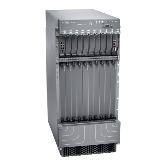
- Page 29 Figure 1: Front View of a Fully Configured MX2008 Router Chassis NOTE: Remove field-replacement units (FRUs) from the front of the MX2008 router before you install the router. Table 3 on page 29 for information about the components on the front of the MX2008 router.
- Page 30 Figure 2: Rear View of a Fully Configured AC-Powered MX2008 Router Chassis Table 4: Rear Components in a Fully Configured AC-Powered MX2008 Router Component No. Component Description Slots Number of FRUs AC PDM— Three-phase delta PDM1/Input1 or wye, or a single-phase AC...
- Page 31 Figure 3: Rear View of a Fully Configured DC-Powered MX2008 Router Chassis NOTE: Remove field replacement units (FRUs) from the rear of the MX2008 router before you install the router. Table 5 on page 31 for information about router components on the back of a DC-powered MX2008 router.
- Page 32 Remove field replacement units (FRUs) from the rear of the MX2008 router before you install the router. The MX2008 router has two ESD points. These are located on either side of the MPCs on the front of the chassis (see Figure 4 on page 32).
-
Page 33: Mx2008 Backplane Description
MX2008 Chassis Moving Guidelines | 194 MX2008 Backplane Description The MX2008 router consist of a signal backplane and a power backplane that connect PSMs and PDMs to the chassis. The adapter cards are carrier cards used to house the MPCs. The MPCs install into the bottom card-cage signal backplanes from the front of the chassis and mate to the signal backplane to connect to the Enhanced Switch Fabric Boards (SFB2s) and the Routing and Control Boards (RCBs). -
Page 34: Mx2008 Component Redundancy
If the master host subsystem (or either of its components) fails, the backup can take over as the master. DC power system—The MX2008 DC power system is made up of three components: nine power supply modules (PSMs), two power distribution modules (PDMs), and a power midplane. The power system distributes power from a pool of 22.5 KW (20 KW for non-redundant PSMs and 2.5 KW reserved for... - Page 35 Description” on page 100. AC power system—The MX2008 supports connection of three-phase and single-phase AC power systems. There are two types of three-phase power systems: the three-phase delta and three-phase wye. The AC power going to the PSMs is split into three individual phases—each PSM works on a single phase.
- Page 36 Figure 6: Power Distribution from Single-Phase Feed Delta PDM to the AC PSMs PDM 1 (feed B) PDM 0 (feed A) Figure 7: Power Distribution from Three-Phase Feed Delta PDM to the AC PSMs AC PS_0 AC PS_3 AC PS_1 AC PS_4 2800W 2800W...
- Page 37 The AC power system is feed redundant—each PSM takes in two AC feeds and uses one of the two. One AC feed is active at a time. If one feed fails, the PSM automatically switches over to the other feed without disrupting system function (see “MX2008 AC Power Supply Module Description” on page 63). AC power requirements—Table 6 on page 37...
-
Page 38: Mx2008 Field-Replaceable Units
This is the minimum required to provide 2.5 KW per PSM. Based on facilities guidelines, you should overprovision the MX2008 router. The two numbers listed in the current columns reflect the distribution of phases from the feed to PSM. For example, from one feed each phase goes to two PSMs and from the other feed each phase goes to only one PSM. - Page 39 DC power distribution modules (if redundant) Fan trays SEE ALSO Tools and Parts Required for Replacing MX2008 Hardware Components | 350 Replacing the MX2008 Craft Interface | 358 Replacing an MX2008 Fan Tray | 374 Replacing an MX2008 MPC | 389...
-
Page 40: Mx2008 Router Hardware Components And Cli Terminology
Replacing an MX2008 RCB | 409 MX2008 Router Hardware Components and CLI Terminology The MX2008 router supports the components listed in Table 8 on page Table 8: MX2008 Router Hardware Components and CLI Terminology Component Hardware Model Number CLI Name... - Page 41 Table 8: MX2008 Router Hardware Components and CLI Terminology (continued) Component Hardware Model Number CLI Name Description PDM blank cover MX2000-PDM-BLANK “MX2008 DC Power Distribution Module (-48 V) Description” on page 96 Power distribution MX2000-PDM-DC DC 52V Power Dist module (PDM)
- Page 42 Table 8: MX2008 Router Hardware Components and CLI Terminology (continued) Component Hardware Model Number CLI Name Description PSM blank cover MX2000-PSM-BLANK “MX2008 Power System Description” on page 58 Power supply module MX2000-PSM-AC AC 52V Power Supply (PSM) Module MX2000-PSM-DC DC 52V Power Supply...
-
Page 43: Mx2008 Craft Interface Description
SEE ALSO MX2008 Router Overview | 25 MX Series Router Interface Names MX2008 Ports and Interfaces | 184 MX2008 Craft Interface Description The craft interface enables the user to view status and troubleshooting information at a glance and to perform many system control functions. It is hot-insertable and hot-removable. - Page 44 Status LEDs for the two RCBs. LC 0 through LC 9 Status LEDs for the ten line cards. SFB 0 through SFB 7 Status LEDs for eight SFBs. SEE ALSO Replacing the MX2008 Craft Interface | 358 MX2008 Craft Interface Serial Number Label | 523...
-
Page 45: Mx2008 Alarm Relay Contacts On The Craft Interface
SEE ALSO Disconnecting the Alarm Relay Wires from the MX2008 Craft Interface | 341 Connecting the Alarm Relay Wires to the MX2008 Craft Interface | 340 MX2008 Alarm LEDs and Alarm Cutoff/Lamp Test Button Two large alarm LEDs are located at the upper right of the craft interface. - Page 46 – Alarm cutoff/lamp Deactivates red and test button yellow alarms. Causes all LEDs on the craft interface to light (for testing) when pressed and held. SEE ALSO MX2008 Craft Interface Serial Number Label | 523 MX2008 Router Overview | 25...
-
Page 47: Mx2008 Component Leds On The Craft Interface
MX2008 Component LEDs on the Craft Interface IN THIS SECTION MX2008 Host Subsystem LEDs and Buttons on the Craft Interface | 47 MX2008 Power Supply Module LEDs on the Craft Interface | 48 MX2008 Line-Card LEDs and Buttons on the Craft Interface | 48... -
Page 48: Mx2008 Power Supply Module Leds On The Craft Interface
When a line card is inserted into an adapter card, and installed into the MX2008 router, the online/offline buttons can turn both the line card and its adapter card on or off. -
Page 49: Mx2008 Sfb Led And Buttons On The Craft Interface
When installing an adapter card without the line card, the online/offline buttons have no effect. MX2008 SFB LED and Buttons on the Craft Interface Each SFB has one bicolor LED on the craft interface that indicates its status. The SFB LEDs, labeled 0 through 7, are located along the bottom of the craft interface. -
Page 50: Mx2008 Cable Manager Description
Extended Cable Manager | 52 The MX2008 router supports the following cable managers: NOTE: The MX2008, MX2010, and MX2020 routers support the same cable managers. Standard Cable Manager The standard cable manager consists of the following components: Card-cage cable manager—MX2000-CBL-MID Lower cable manager—MX2000-CBL-BTM-S... - Page 51 You can pull the DC cable manager up and outward to lock it into the maintenance position. Figure 11: MX2008 Standard Cable Manager Front bottom Rear DC Cable (for DC PDM)
-
Page 52: Extended Cable Manager
Figure 13: Card-Cage Cable Manager Extended Cable Manager The extended cable manager consists of the following components: Extended lower cable manager—MX2000-CBL-BTM-XT-S Extended DC cable manager—MX2020-DC-CBL-MGR-XT-S Figure 14: MX2008 Extended Cable Manager Front lower cable manager Rear DC PDM cable manager... -
Page 53: Mx2008 Rack-Mounting Hardware
To secure the cables in place, loop the tie through the cable anchor and secure the tie. SEE ALSO Replacing the MX2008 Standard Cable Managers Replacing the MX2008 Extended Cable Manager | 354 MX2008 Rack-Mounting Hardware The rack-mounting hardware for the MX2008 router includes:... -
Page 54: Mx2008 Cooling System
Two center-mounting brackets for mounting the router in an open-frame rack (optional) Mounting screws Cage-nuts NOTE: There must be a minimum or 24 U of usable rack space when installing the MX2008 router into a rack. SEE ALSO MX2008 Chassis Description | 27... - Page 55 The cooling system components work together to keep all router components within the acceptable temperature range. The MX2008 router has two fan trays located at the bottom of the router that install horizontally. Each fan tray contains six fans. These are labeled 1 through 6 and each fan is 172 mm in diameter.
- Page 56 Figure 17: Fan Tray Safety double latch system STATUS LED — — Figure 18: Removing the Fan Tray WARNING: Before removing a fan tray, make sure the fan blades have stopped completely. WARNING: The fan trays use a double latch safety mechanism. Press and hold the latch until the STATUS LED turns off.
-
Page 57: Mx2008 Fan Tray Led
Figure 19: Fan Tray Air Filter SEE ALSO Troubleshooting the MX2008 Cooling System | 492 Replacing an MX2008 Fan Tray | 374 Replacing the MX2008 Air Filters | 369 MX2008 Fan Tray LED Each fan tray (both the standard fan tray and optimized power fan tray) contains one tricolor LED located... -
Page 58: Mx2008 Ac Power System
The MX2008 routers are available in a –48 V and 240 V China DC power configuration, three-phase (delta and wye) AC power configurations, and a single-phase power configuration. You can add additional power to the rack as needed. The MX2008 router is configurable with up to two AC or DC power distribution... - Page 59 AC PSMs. The systems configured for single-phase AC input power must use only single phase AC PDMS and AC PSMs. NOTE: The MX2008, MX2010, and MX2020 routers support the same power modules (AC/DC PSMs and AC/DC PDMs). Table 18: MX2008 DC Power Components...
- Page 60 DC Power Supply Modules (PSMs) The MX2008 DC PSMs (-48 V and 240 V China) are hot-removable and hot-insertable. The DC PSMs are a dual redundant feed (INP0 and INP1). To provide feed redundancy, you can connect each DC PSM to two separate feeds from different sources.
- Page 61 200–240 VAC (line-to-line) or three-phase wye 200–240 VAC (line-to-neutral). Each AC PSM is capable of delivering 2500 W of power. The MX2008 router supports the power systems models and Junos OS releases in Table 20 on page...
- Page 62 NOTE: To avoid triggering any PSM-related or power-related alarms for the PSMs that are not used but still plugged into the MX2008 router, make sure that you: Do not connect external power feeds to the PSM through the PDM. Move the DIP switch on the PSMs to the off position.
-
Page 63: Mx2008 Power Midplane Description
MX2008 Power Midplane Description The MX2008 power system consists of a power midplane. This midplane is used to connect power from the PDM feeds (AC or DC) to the input of the PSMs (AC or DC) as well as the output from the PSMs to the FRUs (MPCs, RCBs, SFBs, and fan trays). - Page 64 CAUTION: Do not mix AC and DC PSMs or different PDM types within a single system. The MX2000 line of routers configured for three-phase wye AC input power must use only three-phase wye AC PDMs and three-phase AC PSMs. The systems configured for three-phase delta AC input power must use only three-phase delta AC PDMs and AC PSMs.
-
Page 65: Mx2008 Ac Power Supply Module Leds
A PSM failure triggers the alarm LED on the craft interface. For information about connecting to AC power sources, see “MX2008 AC Power System Electrical Specifications” on page MX2008 AC Power Supply Module LEDs Each AC PSM faceplate contains four LEDs. These LEDs are described in Table 22 on page 66. -
Page 66: Mx2008 Ac Power Supply Module Description | 63
AC input is out of the required voltage range. — AC input to the PSM is not present. SEE ALSO MX2008 Component LEDs on the Craft Interface | 47 MX2008 AC Power Supply Module Description | 63 MX2008 AC Power System Electrical Specifications | 85... -
Page 67: Mx2008 Three-Phase Delta Ac Power Distribution Module Description
MX2008 Three-Phase Delta AC Power Distribution Module Description NOTE: The MX2008, MX2010, and MX2020 routers support the same power modules (AC/DC PSMs and AC/DC PDMs). Each three-phase delta AC power distribution module (PDM) weighs approximately 12 lb (5.44 kg). A metal wiring compartment contains two AC terminal blocks and ground labeled GND. - Page 68 Figure 23: Three-Phase Delta AC Power Distribution Module Connections Figure 24 on page 68 shows the three-phase delta AC power cord. Figure 24: Three-Phase Delta AC Power Cord SEE ALSO MX2008 Power System Description | 58...
-
Page 69: Mx2008 Three-Phase Wye Ac Power Distribution Module Description
MX2008 Three-Phase Wye AC Power Distribution Module Description NOTE: The MX2008, MX2010, and MX2020 routers support the same power modules (AC/DC PSMs and AC/DC PDMs). Each three-phase wye AC PDM weighs approximately 12 lb (5.44 kg). A metal wiring compartment contains two AC terminal blocks and ground labeled GND. - Page 70 CAUTION: The three-phase wye AC PDM must be installed and secured in the chassis before connecting the power input cables. If the PDM must be removed, both input power cables must be uninstalled and removed from the PDM before the PDM can be removed from the chassis.
-
Page 71: Mx2008 Nine-Feed Single-Phase Ac Power Distribution Module Description
The MX2008, MX2010, and MX2020 routers support the same power modules (AC/DC PSMs and AC/DC PDMs). The MX2008 nine-feed single-phase AC power distribution module (PDM) provides AC input connection from a single-phase AC source, and also provides an input power interface to the power supply module (PSM) through a system power midplane. -
Page 72: Mx2008 Seven-Feed Single Phase Ac Power Distribution Module Description
PDM before the PDM can be removed from the chassis. SEE ALSO MX2008 Power System Description | 58 MX2008 AC Power System Electrical Specifications | 85 MX2008 AC Power Cord Specifications | 82 MX2008 Seven-Feed Single Phase AC Power Distribution Module Description Each single-phase seven-feed AC PDM weighs approximately 12 lb (5.44 kg). -
Page 73: Mx2008 Three-Phase Delta And Wye Ac Power Distribution Module Leds
MX2008 AC Power Cord Specifications | 82 MX2008 Three-Phase Delta and Wye AC Power Distribution Module LEDs NOTE: The MX2008, MX2010, and MX2020 routers support the same power modules (AC/DC PSMs and AC/DC PDMs). Figure 30 on page 73 shows the LEDs on the three-phase delta AC PDM faceplate. The three-phase wye AC PDM has the same LEDs. -
Page 74: Mx2008 Ac Power Requirements
MX2008 AC Power System Electrical Specifications | 85 MX2008 AC Power Requirements NOTE: The MX2008, MX2010, and MX2020 routers support the same power modules (AC/DC PSMs and AC/DC PDMs). To allow for future growth so that you can operate the router in any hardware configuration without upgrading the power infrastructure, we recommend that you provision 2800 W for each AC PDM (delta or wye). - Page 75 2800 W 50 A/25 A 2800 W MX2008 three-phase wye power system (PDM and PSM) @ 30 A/15 A If you do not plan to provision as recommended above, you can use the information in Table 26 on page 75 to calculate the power consumption for your hardware configuration.
- Page 76 Table 26: MX2008 FRU AC Power Requirements (continued) Component Model Number Maximum Power Requirement MX2000-LC-ADAPTER 150 W Routing Control Board REMX2008-X8-64G 100 W (Typical) 120 W at 55° C 100 W at 40° C 95 W at 25° C MPCs...
- Page 77 Table 26: MX2008 FRU AC Power Requirements (continued) Component Model Number Maximum Power Requirement MPC2 Q (see MPC2 Q ) MX-MPC2-3D-Q 294 W MPC2 EQ (see MPC2 EQ ) MX-MPC2-3D-EQ With MICs and optics: 368 W at 55° C MX-MPC2E-3D-Q 347 W at 40°...
- Page 78 Table 26: MX2008 FRU AC Power Requirements (continued) Component Model Number Maximum Power Requirement 2x100GE + 8x10GE MPC4E (see MX-MPC4E-2CGE-8XGE 610 W 2x100GE + 8x10GE MPC4E) With MICs and optics: 610 W at 55° C, two 40 W MICs 550 W at 40° C, two CFP MICs with LR4 optics 530 W at 25°...
- Page 79 Table 26: MX2008 FRU AC Power Requirements (continued) Component Model Number Maximum Power Requirement MPC8E MX2K-MPC8E 688 W (Typical) (without MICs) 805 W at 55° C 720 W at 40° C 690 W at 25° C MPC9E MX2K-MPC9E 838 W (Typical) (without MICs) 1018 W at 55°...
- Page 80 Table 26: MX2008 FRU AC Power Requirements (continued) Component Model Number Maximum Power Requirement 10-Gigabit Ethernet DWDM OTN MIC6-10G-OTN 84 W With optics: 63 W at 55° C with 10G BASE-LR OTN optics 63 W at 40° C with 10G BASE-LR OTN optics 63 W at 25°...
- Page 81 Table 26: MX2008 FRU AC Power Requirements (continued) Component Model Number Maximum Power Requirement 100-Gigabit DWDM OTN MIC MIC3-100G-DWDM With optics: with CFP2 91 W at 55° C 83 W at 25° C SONET/SDH OC3/STM1 4-Port: MIC-3D-4OC3OC12-1OC48 4-Port: Multi-Rate MIC 8-Port: MIC-3D-8OC3OC12-4OC48 24 W at 55°...
-
Page 82: Mx2008 Ac Power Cord Specifications
MX2008 AC Power System Electrical Specifications | 85 MX2008 AC Power Cord Specifications NOTE: The MX2008, MX2010, and MX2020 routers support the same power modules (AC/DC PSMs and AC/DC PDMs). Most sites distribute power through a main conduit that leads to frame-mounted power distribution panels, one of which can be located next to the rack that houses the router. - Page 83 Detachable AC power cords, each approximately 14.8 ft (4.5 m) long, are supplied with the router. The AC power cord wires are inserted into the AC input terminal with the help of a screwdriver. The plug end of the power cord fits into the power source receptacle for your geographical location. Table 27 on page 83 Table 28 on page 83 provide specifications for the AC power cords for each...
- Page 84 Figure 31: Three-Phase Delta AC Power Cord Figure 32: Three-Phase Wye AC Power Cord Figure 33: Single-Phase AC Power Cord (C21 plug)
-
Page 85: Mx2008 Ac Power System Electrical Specifications
Replacing an MX2008 AC Power Supply Module | 422 MX2008 AC Power System Electrical Specifications NOTE: The MX2008, MX2010, and MX2020 routers support the same power modules (AC/DC PSMs and AC/DC PDMs). Table 29 on page 86 lists the AC power system electrical specifications for the MX2000 line of routers. -
Page 86: Ac Power Supply Input Fuses
Table 29: MX2008 AC Power System Electrical Specifications Item Specification AC input voltage Delta operating range: 200–240 VAC (line-to-line) (nominal) Wye operating range: 200–240 VAC (line-to-neutral) (nominal) Single-phase operating range: 200-240 VAC (nominal) AC input line frequency Delta: 50/60 Hz (+/-3Hz) -
Page 87: Mx2008 Ac Power Electrical Safety Guidelines
Preventing Electrostatic Discharge Damage to an MX2008 Router | 544 MX2008 AC Power Electrical Safety Guidelines NOTE: The MX2008, MX2010, and MX2020 routers support the same power modules (AC/DC PSMs and AC/DC PDMs). NOTE: For devices with AC power supplies, an external surge protective device (SPD) must be... - Page 88 Power Cable Warning (Japanese) WARNING: The attached power cable is only for this product. Do not use the cable for another product. SEE ALSO Preventing Electrostatic Discharge Damage to an MX2008 Router | 544 MX2008 AC Power Requirements | 74...
-
Page 89: Mx2008 Three-Phase Delta Ac Power Distribution Module Electrical Specifications
MX2008 Three-Phase Delta AC Power Distribution Module Electrical Specifications NOTE: The MX2008, MX2010, and MX2020 routers support the same power modules (AC/DC PSMs and AC/DC PDMs). Table 31 on page 89 lists the three-phase delta AC power distribution monitor (PDM) electrical specifications. -
Page 90: Mx2008 Three-Phase Wye Ac Power Distribution Module Electrical Specifications
MX2008 Three-Phase Wye AC Power Distribution Module Electrical Specifications NOTE: The MX2008, MX2010, and MX2020 routers support the same power modules (AC/DC PSMs and AC/DC PDMs). Table 32 on page 90 lists the three-phase wye AC PDM electrical specifications. Table 32: Three-Phase Wye AC Power Distribution Module Electrical Specifications... -
Page 91: Mapping Input Power From Ac Power Distribution Modules To Ac Power Supply Modules On Mx2008 Router
Supply Modules on MX2008 Router NOTE: The MX2008, MX2010, and MX2020 routers support the same power modules (AC/DC PSMs and AC/DC PDMs). You connect AC power to the router by connecting two AC power cords to each AC PDM. One feed maps to six PSMs and the other maps to three PSMs. - Page 92 Figure 34: Mapping AC Power Distribution Module Input to AC Power Supply Modules (MX2008) Table 34: Input AC Power Mapping for PDM0 and PDM1 PDM0/Input0 (Left) PDM0/Input0 (Right) PDM1/Input1 (Left) PDM1/Input1 (Right) PSM0 PSM3 PSM0 PSM6 PSM1 PSM4 PSM1 PSM7...
-
Page 93: Mx2008 Dc Power System
MX2008 DC Power (-48 V) System Electrical Specifications | 117 MX2008 Router DC (240 V China) System Electrical Specifications | 118 DC Power (-48 V) Circuit Breaker Requirements for the MX2008 Router | 119 DC Power (240 V China) Circuit Breaker Requirements for the MX2000 Router | 120... -
Page 94: Mx2008 Seven-Feed Dc Power Distribution Module Description
In the DC power configuration, the router contains up to two DC PDMs located at the rear of the chassis in slots PDM0/Input0 and PDM1/Input1 (bottom to top). A minimum of one PDM is required per system (two PDMs per MX2008 chassis) for nonredundant power. The DC PDMs provides power interface to nine PSMs. - Page 95 MX2008 DC Power Distribution Description (-48 V) | 113 Calculating DC Power Requirements for MX2008 Routers | 222 MX2008 DC Power Requirements | 105 MX2008 DC Power (-48 V) System Electrical Specifications | 117 Site Electrical Wiring Guidelines for MX Series Routers | 590...
-
Page 96: Mx2008 Dc Power Distribution Module (-48 V) Description
MX2008 DC Power Distribution Module (-48 V) Description NOTE: The MX2008, MX2010, and MX2020 routers support the same power modules (AC/DC PSMs and AC/DC PDMs). In the DC power configuration, the router contains up to two DC power distribution modules (PDMs) located at the rear of the chassis in slots PDM0/Input0 and PDM1/Input1 (bottom to top). -
Page 97: Mx2000 Dc Power Distribution Module (240 V China) Description
DIP switch positions in the PDM. SEE ALSO Calculating DC Power Requirements for MX2008 Routers | 222 MX2008 DC Power (-48 V) System Electrical Specifications | 117 MX2008 Power System Description | 58 Site Electrical Wiring Guidelines for MX Series Routers | 590... -
Page 98: Mx2008 Dc Power Distribution Module (-48 V) Leds
MX2008 DC Power Distribution Module (-48 V) LEDs NOTE: The MX2008, MX2010, and MX2020 routers support the same power modules (AC/DC PSMs and AC/DC PDMs). Each DC PDM faceplate contains one bicolor LED for each of the nine –48 V input power feeds, indicating the correct or incorrect polarity connection of each feed. -
Page 99: Mx2000 Dc Power Distribution Module (240 V China) Leds
RTN and –48V input feeds are not connected. RTN or –48V input feeds may be reversed, feed live. SEE ALSO MX2008 Component LEDs on the Craft Interface | 47 MX2008 Power System Description | 58 MX2000 DC Power Distribution Module (240 V China) LEDs Each DC PDM (240 V China) faceplate contains one LED for each of the nine input power feeds, indicating the correct or incorrect polarity connection of each feed. -
Page 100: Mx2008 Dc Power Supply Module (-48 V) Description
PSMs and AC/DC PDMs). The MX2008 supports a DC power system. The DC power system operates with feeds of 60 A or 80 A current limited. A total of nine feeds are required to fully power the MX2008. Another nine feeds are required to provide feed redundancy (a total of 18 60-A or 80-A feeds). - Page 101 102). In addition, a PSM failure triggers the alarm LED on the craft interface. Each PDM has an LED per feed indicating whether the feed is active or not, or whether the feed is connected properly, see “MX2008 DC Power (-48 V) System Electrical Specifications” on page 117.
-
Page 102: Mx2000 Dc Power Supply Module (240 V China) Description
The MX2008 supports a DC power system. The 240 V China DC power system operates with nine feeds. A total of nine feeds are required to fully power the MX2008. Another nine feeds are required to provide feed redundancy (a total of 18 feeds In the DC power configuration, the router contains up to nine DC PSMs located at the rear of the chassis in slots PSM0 through PSM8, (left to right). - Page 103 102). In addition, a PSM failure triggers the alarm LED on the craft interface. Each PDM has an LED per feed indicating whether the feed is active or not, or whether the feed is connected properly, see “MX2008 Router DC (240 V China) System Electrical Specifications” on page 118.
- Page 104 Figure 43: Selecting Input Feed on the DC Power Supply Module (240 V China) MX2008 DC Power Supply Module LEDs Each DC PSM (-48 V and 240 China) faceplate contains four LEDs. These LEDs are described in Table 39 on page 105.
- Page 105 DC input to the PSM is not present. SEE ALSO MX2008 Router Grounding Specifications | 203 Site Electrical Wiring Guidelines for MX Series Routers | 590 MX2008 DC Power Requirements NOTE: The MX2008, MX2010, and MX2020 routers support the same power modules (AC/DC PSMs and AC/DC PDMs).
- Page 106 NOTE: Unlike all the other MPCs, MPC6E, MPC8E, and MPC9E does not require an adapter card (ADC) to house the MPC in the MX2008 router. Table 40: FRU DC Power Requirements Component...
- Page 107 Table 40: FRU DC Power Requirements (continued) Component Model Number Maximum Power Requirement Routing Control Board (RCB) REMX2008-X8-64G 100 W (Typical) 120 W at 55° C 100 W at 40° C 95 W at 25° C MPCs 16x10GE MPC MPC-3D-16XGE-SFPP 440 W at 55°...
- Page 108 Table 40: FRU DC Power Requirements (continued) Component Model Number Maximum Power Requirement MPC2 Q (see MPC2 Q) MX-MPC2-3D-Q 294 W MPC2 EQ (see MPC2 EQ) MX-MPC2-3D-EQ With MICs and optics: 368 W at 55° C MX-MPC2E-3D-Q 347 W at 40° C MX-MPC2E-3D-EQ 333 W at 25°...
- Page 109 Table 40: FRU DC Power Requirements (continued) Component Model Number Maximum Power Requirement 2x100GE + 8x10GE MPC4E (see MX-MPC4E-2CGE-8XGE 610 W 2x100GE + 8x10GE MPC4E) With MICs and optics: 610 W at 55° C, two 40 W MICs 550 W at 40° C, two CFP MICs with LR4 optics 530 W at 25°...
- Page 110 Table 40: FRU DC Power Requirements (continued) Component Model Number Maximum Power Requirement MPC9E MX2K-MPC9E 838 W (Typical) (without MICs) 1018 W at 55° C 870 W at 40° C 840 W at 25° C MICs ATM MIC with SFP MIC-3D-8OC3-2OC12-ATM 35 W Gigabit Ethernet MIC with SFP...
- Page 111 Table 40: FRU DC Power Requirements (continued) Component Model Number Maximum Power Requirement 40-Gigabit Ethernet MIC with MIC3-3D-2X40GE-QSFPP 18 W QSFPP 100-Gigabit Ethernet MIC with MIC3-3D-1X100GE-CFP 40 W 100-Gigabit Ethernet MIC with MIC3-3D-1X100GE-CXP 20 W 100-Gigabit Ethernet MIC with MIC6-100G-CFP2 104 W CFP2 With optics:...
- Page 112 Table 40: FRU DC Power Requirements (continued) Component Model Number Maximum Power Requirement SONET/SDH OC3/STM1 4-Port: MIC-3D-4OC3OC12-1OC48 4-Port: Multi-Rate MIC 8-Port: MIC-3D-8OC3OC12-4OC48 24 W at 55° C 22.75 W at 40° C 21.5 W at 25° C 8-Port: 29 W at 55° C 27.75 W at 40°...
- Page 113 These feeds are set by the input mode DIP switch located on the DC PSM (see “MX2008 DC Power Supply Module (-48 V) Description” on page 100). Each set of power cables powers a single DC PSM and is capable of delivering 2500 W of power if 80-A feeds are connected.
- Page 114 Figure 44 on page 114 shows a typical DC source cabling arrangement. Figure 44: Typical DC Source Cabling to the Router All DC PSMs in a subsystem share the load. If one PSM fails in a redundant configuration, the remaining PSMs provide power to FRUs.
- Page 115 MX2008 DC Power Distribution Module (-48 V) Description | 96MX2008 Power System Description | 58 MX2008 DC Power Distribution Module (-48 V) Description | 96 Replacing an MX2000 DC Power Distribution Module (-48 V) Replacing an MX2020 Three-Phase Wye AC Power Distribution Module | 446...
- Page 116 Figure 45: Typical DC Source Cabling to the Router DC power supply on MX2008 Rectifiers Central office secondary DC power distribution Plant controls Batteries Power plant and batteries in same building Safety ground Chassis grounding point connection All DC PSMs in a subsystem share the load. If one PSM fails in a redundant configuration, the remaining PSMs provide power to FRUs.
- Page 117 MX2008 DC Power (-48 V) System Electrical Specifications NOTE: The MX2008, MX2010, and MX2020 routers support the same power modules (AC/DC PSMs and AC/DC PDMs). Table 41 on page 117 lists the DC power system electrical specifications. Table 41: DC PSM Electrical Specifications per Input Configurations...
- Page 118 SEE ALSO MX2008 Power System Description | 58 MX2008 DC Power Distribution Module (-48 V) Description | 96 MX2008 DC Power Supply Module (-48 V) Description | 100 MX2008 Router DC (240 V China) System Electrical Specifications Table 42 on page 118 lists the DC power system electrical specifications.
- Page 119 DC Power (-48 V) Circuit Breaker Requirements for the MX2008 Router NOTE: The MX2008, MX2010, and MX2020 routers support the same power modules (AC/DC PSMs and AC/DC PDMs). For PDMs, if you plan to operate a maximally configured DC-powered router, we recommend that you provision at least 80 A @ –48 VDC (nominal) for each DC input to the system.
- Page 120 125% of the continuous current that the system draws at 240 VDC. DC Power Cable Specifications for the MX2008 Router NOTE: The MX2008, MX2010, and MX2020 routers support the same power modules (AC/DC PSMs and AC/DC PDMs).
- Page 121 Figure 46 on page 121 Figure 47 on page 121). NOTE: The MX2008 supports 4-AWG DC power cable lugs for 80-A input, and 6-AWG DC power cable lugs for 60-A input. Figure 46: 4-AWG DC Power Cable Lug End view Inner diameter .28...
- Page 122 MX2008 DC Power Distribution Module (-48 V) Description | 96 MX2008 DC Power Supply Module (-48 V) Description | 100 Replacing an MX2000 DC Power Distribution Module (-48 V) Replacing an MX2008 DC Power Supply Module (-48 V) | 465 MX2008 Host Subsystem IN THIS SECTION...
- Page 123 These routing processes run on top of a kernel that interacts with the Packet Forwarding Engine. The MX2008 host subsystem consists of two Routing and Control Boards, or RCBs. The RCB is an integrated board and a single FRU that provides Routing Engine and Control Board functionality.
- Page 124 RCB Front Panel | 125 RCB Interface Ports | 127 The MX2008 Routing and Control Board (MX2008 RCB) is an integrated board and a single FRU that provides Routing Engine and Control Board functionality. The REMX2008-X8-128G RCB is equipped with a 8-Core 2.3 GHz processor, 128 GB memory, and two 200 GB SSDs and also supports Secure Boot for enhanced boot security.
- Page 125 RCB Function The RCB runs Junos OS. Software processes that run on the RCB maintain the routing tables, manage the routing protocols used on the router, control the router interfaces, control some chassis components, and provide the interface for system management and user access to the router. RCB Slots The user can install one or two RCBs in the router.
- Page 126 This port is used to install a USB flash drive that contains Junos OS. This port is a dedicated management channel for device maintenance. It is also used for system administrators to monitor and manage the MX2008 router remotely.
- Page 127 Function No. Label Description CONSOLE This port is used to configure the MX2008 router. RCB Interface Ports Three ports, located on the RCB, connect the RCB to one or more external devices on which system administrators can issue Junos OS CLI commands to manage the router. In addition, four ports located on the RCB include, two 10-Gigabit Ethernet SFP+ interface connectors supporting hardware diagnostics (JCS port testing), and two external clock interfaces for BITS and GPS function.
- Page 128 RJ-45 Connector Pinouts for MX Series CB-RE or RCB Auxillary and Console Ports | 215 RJ-45 Connector Pinouts for an MX Series CB-RE or RCB Management Port | 216 Replacing an MX2008 RCB | 409 MX2008 Host Subsystem Description | 123...
- Page 129 Figure 51: RCB LEDs Table 46: RCB LEDs Function Label Color State Description ONLINE Green Blinking RCB is starting BIOS. slow Blinking RCB is starting Linux. fast Both Junos OS and Linux are successfully loaded steadily on the RCB. – RCB is offline.
- Page 130 BITS external clocking interface is offline. Green Global positioning system (GPS) external clocking steadily interface is active. GPS external clocking interface has failed. steadily – GPS external clocking interface is offline. SEE ALSO MX2008 Host Subsystem Description | 123 Replacing an MX2008 RCB | 409...
- Page 131 Routing Engine Specifications Table 47 on page 131 lists the current specifications for Routing Engines supported on M Series, MX Series, and T Series routers. Table 48 on page 135 lists the hardware specifications of the Routing Engines with VMHost support. Table 49 on page 137 lists the specifications for end-of-life Routing Engines.
- Page 132 Table 47: Routing Engine Specifications (continued) First Switch Connection Junos OS Control Routing Engine Processor Memory to PFEs Disk Media Support Board RE-C1800 1.8-GHz 8 GB Gigabit 4 GB T1600 CB-T for a Ethernet CompactFlash router in a standalone card routing router.
- Page 133 Table 47: Routing Engine Specifications (continued) First Switch Connection Junos OS Control Routing Engine Processor Memory to PFEs Disk Media Support Board RE-C2600 2.6-GHz 16 GB Gigabit 4 GB TX Matrix – Ethernet CompactFlash Plus router: card 9.6R2 RE-A-1800x2 1800-MHz 8 GB or Gigabit 32 GB...
- Page 134 Table 47: Routing Engine Specifications (continued) First Switch Connection Junos OS Control Routing Engine Processor Memory to PFEs Disk Media Support Board RE-S-X6-64G, 2 Ghz 64 GB Gigabit 15.1F4, SCBE2, RE-S-X6-64G-LT Ethernet 50-GB 16.1 SCBE3 SSDs REMX2K-X8-64G 2.3 Ghz 64 GB Gigabit 15.1F5-S1, –...
- Page 135 Table 47: Routing Engine Specifications (continued) First Switch Connection Junos OS Control Routing Engine Processor Memory to PFEs Disk Media Support Board JNP10003-RE1 1.6-GHz 64 GB Gigabit 17.3R1 Ethernet 100 GB SSDs JNP10003-RE1-LT 1.6-GHz 64 GB Gigabit 18.1R1 Ethernet 100 GB SSDs JNP10K-RE0 2.5 GhZ...
- Page 136 Table 48: Hardware Specifications of the RE-MX-X6, RE-MX-X8, RE-PTX-X8, RCBPTX, RE-QFX10002-60C, and RE-PTX10002-60C Routing Engines (continued) Model Number Supported on Device Specifications REMX2K-X8-64G MX2020 and MX2010 8-core Haswell CPU Wellsburg PCH-based Routing Engine with 64-GB DRAM and two 64-GB SSDs RE-PTX-X8-64G PTX5000 8-core Haswell CPU...
- Page 137 Table 49: End-of-Life Routing Engine Specifications Routing Connection First Junos Engine Processor Memory to PFEs Disk Media OS Support EOL Details RE-333-256 333-MHz 256 MB Fast 6.4 GB 80 MB PSN-2003-01-063 Pentium II Ethernet hard disk CompactFlash card RE-333-768 333-MHz 768 MB Fast 6.4 GB...
- Page 138 MX204 Routing Engine | 143 MX240 Routing Engines | 143 MX480 Routing Engines | 144 MX960 Routing Engines | 146 MX2008 Routing Engines | 147 MX2010 Routing Engines | 147 MX2020 Supported Routing Engines | 148 MX10003 Routing Engines | 149...
- Page 139 T4000 Routing Engines | 155 TX Matrix Routing Engines | 156 TX Matrix Plus Routing Engines | 157 TX Matrix Plus (with 3D SIBs) Routing Engines | 157 The following tables list the Routing Engines that each router supports, the first supported release for the Routing Engine in the specified router, the management Ethernet interface, and the internal Ethernet interfaces for each Routing Engine.
- Page 140 Table 51: M10i Routing Engines First Supported Management Name in CLI 32-bit Junos OS Ethernet Internal Ethernet Model Number Output Release Interface Interface RE-400-768 (EOL details: RE-5.0 fxp0 fxp1 TSB16445) fxp2 RE-850-1536 (EOL details: RE-850 fxp0 fxp1 TSB15553) fxp2 RE-B-1800X1-4G RE-B-1800x1 11.4R4 fxp0...
- Page 141 Table 53: M120 Routing Engines First First Supported Supported Management Internal Name in CLI 32-bit Junos OS 64-bit Junos Ethernet Ethernet Model Number Output Release OS Release Interface Interface RE-A-1000-2048 RE-A-1000 8.0R2 – fxp0 fxp1 fxp2 RE-A-2000-4096 RE-A-2000 8.0R2 – fxp0 bcm0 RE-A-1800X2-8G...
- Page 142 Table 54: M320 Routing Engines (continued) First First Supported Supported Management Internal Name in CLI 32-bit Junos OS 64-bit Junos Ethernet Ethernet Model Number Output Release OS Release Interface Interface RE-A-1800X2-8G RE-A-1800x2 11.4R5 10.4 fxp0 12.1R3 bcm0 RE-A-1800X2-16G RE-A-1800x2 11.4R5 10.4 fxp0 12.1R3...
- Page 143 Table 56: MX104 Routing Engines First Supported First Supported Management Internal Model Name in CLI 32-bit Junos OS 64-bit Junos OS Ethernet Ethernet Number Output Release Release Interface Interface RE-S-MX104 Routing Engine 13.2 – fxp0 fxp1 fxp2 MX204 Routing Engine Table 57 on page 143 lists the Routing Engines supported by the MX204 router.
- Page 144 Table 58: MX240 Supported Routing Engines (continued) First Supported First Supported Management Internal Name in CLI 32-bit Junos 64-bit Junos Ethernet Ethernet Model Number Output OS Release OS Release Interface Interface RE-S-1800X2-8G RE-S-1800x2 11.4R5 10.4 fxp0 (EOL details: 12.1R3 TSB16556 RE-S-1800x2-16G RE-S-1800x2 11.4R5...
- Page 145 Table 59: MX480 Supported Routing Engines First Supported First Supported Management Internal Name in CLI 32-bit Junos 64-bit Junos Ethernet Ethernet Model Number Output OS Release OS Release Interface Interface RE-S-1300-2048 RE-S-1300 – fxp0 fxp1 (EOL details: fxp2 TSB16556 RE-S-2000-4096 RE-S-2000 –...
- Page 146 MX960 Routing Engines Table 60 on page 146 lists the Routing Engines supported by MX960 routers. Table 60: MX960 Supported Routing Engines First First Supported Supported Management Internal Name in CLI 32-bit Junos 64-bit Junos Ethernet Ethernet Model Number Output OS Release OS Release Interface...
- Page 147 RE-S-X6-128G RE-S-1600x8-128 – 18.1R1 fxp0 ixlv0, igb0 MX2008 Routing Engines Table 61 on page 147 lists the Routing Engines supported by MX2008 routers. Table 61: MX2008 Supported Routing Engines Management Internal Name in CLI First Supported 64-bit Ethernet Ethernet Model Number...
- Page 148 Table 62: MX2010 Supported Routing Engines (continued) Management Internal Name in CLI First Supported 64-bit Ethernet Ethernet Model Number Output Junos OS Release Interface Interface REMX2K-1800-32G-S RE-S-1800x4 12.3R4 fxp0 13.2R1 REMX2K-X8-64G RE-S-2X00x8 15.1F5-S1 fxp0 ixlv0 16.1R2 ixlv1 16.2R1 REMX2K-X8-64G-LT RE-S-2X00x8 17.2R1 fxp0 ixlv0...
- Page 149 Table 63: MX2020 Supported Routing Engines (continued) Management Internal Name in CLI First Supported 64-bit Ethernet Ethernet Model Number Output Junos OS Release Interface Interface REMX2K-X8-64G-LT RE-S-2X00x8 17.2R1 fxp0 ixlv0 ixlv1 REMX2K-X8-128G RE-MX200X8-128G 18.1R1 fxp0 ixlv0 ixlv1 MX10003 Routing Engines Table 64 on page 149 lists the Routing Engines supported by MX10003 routers.
- Page 150 Table 65: MX10008 Routing Engines Name in CLI First Supported Management Internal Ethernet Model Number Output Junos OS Release Ethernet Interface Interface JNP10K-RE1 RE X10 18.2R1 bme0 bme1 PTX1000 Routing Engines Table 66 on page 150 lists the Routing Engine supported on the PTX1000. NOTE: The PTX1000 supports 64-bit Junos OS only.
- Page 151 Table 67: PTX3000 Routing Engines (continued) Management Name in CLI First Supported Junos OS Ethernet Internal Ethernet Model Number Output Release Interface Interface RCB-PTX-X6-32G RE-PTX-2X00x6 16.1R4 ixlv0 17.1R1 ixlv1 This Routing Engine does not support Junos OS Release 16.2. PTX5000 Routing Engines Table 68 on page 151 lists the Routing Engines supported on the PTX5000.
- Page 152 Table 68: PTX5000 Routing Engines (continued) Management Internal First Supported Junos Ethernet Ethernet Model Number Name in CLI Output OS Release Interface Interface RE-PTX-X8-64G RE-PTX-2X00x8 15.1F4 ixlv0 16.1R1 ixlv1 RE-PTX-X8-128G RE-PTX-2X00x8-128G 18.1R1 ixlv0 ixlv1 PTX10008 and PTX10016 Routing Engines Table 69 on page 152 lists the Routing Engines supported on the PTX10008 and PTX10016 routers.
- Page 153 Table 70: T320 Routing Engines First Supported Management Name in CLI 32-bit Junos OS Ethernet Internal Ethernet Model Number Output Release Interface Interface RE-600-2048 (EOL details: RE-3.0 or RE-3.0 fxp0 fxp1 TSB14373) (RE-600) fxp2 RE-1600-2048 (EOL details: RE-4.0 fxp0 fxp1 TSB14374 fxp2 RE-A-2000-4096...
- Page 154 Table 71: T640 Routing Engines (continued) First Supported First Supported Management Internal Name in CLI 32-bit Junos OS 64-bit Junos OS Ethernet Ethernet Model Number Output Release Release Interface Interface RE-DUO-C1800-8G RE-DUO-1800 32-bit Junos OS on 64-bit Junos OS on bcm0 a standalone T640 a standalone T640...
- Page 155 Table 72: T1600 Routing Engines (continued) First Supported First Supported Management Internal Name in CLI 32-bit Junos OS 64-bit Junos OS Ethernet Ethernet Model Number Output Release Release Interface Interface RE-1600-2048 (EOL RE-4.0 – fxp0 fxp1 details: TSB14374 (RE-1600) fxp2 RE-A-2000-4096 RE-A-2000 –...
- Page 156 NOTE: The T4000 router supports 64-bit Junos OS only. Table 73: T4000 Routing Engines Management Internal Name in CLI First Supported 64-bit Junos Ethernet Ethernet Model Number Output OS Release Interface Interface RE-DUO-C1800-8G RE-DUO-1800 Standalone T4000 router: 12.1 bcm0 T4000 router in a routing matrix: 13.1 RE-DUO-C1800-16G RE-DUO-1800...
- Page 157 Table 74: TX Matrix Routing Engines (continued) First First Supported Supported Management Internal Name in CLI 32-bit Junos 64-bit Junos Ethernet Ethernet Model Number Output OS Release OS Release Interface Interface RE-DUO-C1800-8G RE-DUO-1800 11.4R9 11.4R9 bcm0 RE-DUO-C1800-16G RE-DUO-1800 11.4R9 11.4R9 bcm0 The TXP router supports two control boards, CB-TX and CB-LCC.
- Page 158 RE-TXP-SFC or 64-bit Junos OS: ixgbe0 RE-DUO-2600 11.4 ixgbe1 SEE ALSO Understanding Internal Ethernet Interfaces Understanding Management Ethernet Interfaces MX2008 Switch Fabric Boards IN THIS SECTION MX2008 Enhanced Switch Fabric Board (MX2008 SFB2) Description | 159 MX2008 SFB LED | 160...
- Page 159 MX2000 SFB2 has two PF fabric chips per card whereas MX2008 SFB2 has only one PF fabric chip per card, and that MX2008 SFB2 is less than half the size of the native MX2000 SFB2.
- Page 160 SEE ALSO Replacing an MX2008 SFB | 406 MX2008 SFB LED One bicolor LED on the MX2008 SFB2 indicates the status of the SFB. The LED, labeled OK/FAIL, is located directly on the SFB. Table 77 on page 161 describes the functions of the MX2008 SFB2 LED.
- Page 161 Each SFB also has a set of bicolor LEDs on the craft interface that indicate its status. The SFB LED, labeled 0 through 7, are located along the bottom center of the craft interface. For more information about the SFB LEDs on the craft interface, see “MX2008 Component LEDs on the Craft Interface” on page...
- Page 162 MX2008 Interface Modules IN THIS SECTION MX2000 Adapter Card (ADC) Description | 162 MX2008 Modular Port Concentrator Description | 163 MX2008 Modular Port Concentrator LEDs | 166 MPCs Supported by MX Series Routers | 166 MX2008 MPC Terminology | 171...
- Page 163 Maintaining the MX2010 Adapter Cards Maintaining MX2020 Adapter Cards MPCs Supported by MX Series Routers | 166 Replacing an MX2008 MPC | 389 MX2008 Modular Port Concentrator Description The Modular Port Concentrators (MPCs) provide packet forwarding services. An MPC installs into an...
- Page 164 Figure 55 on page 164 shows a typical MPC supported on the MX2008 router. Figure 56 on page 165 shows an MPC installed vertically in the MX2008 router. For more information about MPCs, see the MX Series Interface Module Reference.
- Page 165 Figure 56: MPC Installed in the MX2008 Router MPC Components Each MPC consists of the following components: MIC card carrier, which includes two MIC slots (excludes the fixed-configuration MPC). Fabric interfaces. Two Gigabit Ethernet interfaces that allow control information, route information, and statistics to be sent between the Routing Engine and the CPU on the MPCs.
- Page 166 MX2008 Field-Replaceable Units | 38 Maintaining Cables That Connect to MX2008 MPCs or MICs | 485 Replacing an MX2008 MPC | 389 Troubleshooting the MX2008 MPCs | 512 MX2000 Adapter Card (ADC) Description | 162 MX2008 Modular Port Concentrator LEDs One bicolor LED located on the craft interface above the MPC, displays the status of the MPC.
- Page 167 Table 78: MPCs Supported by MX240, MX480, MX960, MX2008, MX2010, MX2020, and MX10003 Routers First Junos OS Release First Junos First First First First MX240, Junos OS Junos OS Junos OS Junos OS MX480, Release Release Release Release Release MX960...
- Page 168 Table 78: MPCs Supported by MX240, MX480, MX960, MX2008, MX2010, MX2020, and MX10003 Routers (continued) First Junos OS Release First Junos First First First First MX240, Junos OS Junos OS Junos OS Junos OS MX480, Release Release Release Release Release...
- Page 169 Table 78: MPCs Supported by MX240, MX480, MX960, MX2008, MX2010, MX2020, and MX10003 Routers (continued) First Junos OS Release First Junos First First First First MX240, Junos OS Junos OS Junos OS Junos OS MX480, Release Release Release Release Release...
- Page 170 Table 78: MPCs Supported by MX240, MX480, MX960, MX2008, MX2010, MX2020, and MX10003 Routers (continued) First Junos OS Release First Junos First First First First MX240, Junos OS Junos OS Junos OS Junos OS MX480, Release Release Release Release Release...
- Page 171 Table 78: MPCs Supported by MX240, MX480, MX960, MX2008, MX2010, MX2020, and MX10003 Routers (continued) First Junos OS Release First Junos First First First First MX240, Junos OS Junos OS Junos OS Junos OS MX480, Release Release Release Release Release...
- Page 172 Figure 57: MPC Edges SEE ALSO MX2008 Component LEDs on the Craft Interface | 47 Troubleshooting the MX2008 MPCs | 512 Replacing an MX2008 MPC | 389 MX2008 Modular Interface Card Description The Modular Interface Cards (MICs) install into the Modular Port Concentrators (MPCs) and provide the physical connections to various network media types.
- Page 173 MX2008 Modular Interface Card LEDs | 183 Maintaining Cables That Connect to MX2008 MPCs or MICs | 485 Troubleshooting the MX2008 MICs | 511 Replacing an MX2008 MIC | 378 MICs Supported by MX Series Routers The following tables list the first supported Junos OS release for the MX Series.
- Page 174 Table 79: MICs Supported by MX240, MX480, MX960 and MX2008 Routers (continued) MX240, MX480, and MX2008 MIC Name MIC Model Number Ports MX960 Routers Routers Gigabit Ethernet MIC with SFP MIC-3D-20GE-SFP 10.1 15.1F7 Gigabit Ethernet MIC with SFP MIC-3D-20GE-SFP-E 13.3 15.1F7...
- Page 175 Table 79: MICs Supported by MX240, MX480, MX960 and MX2008 Routers (continued) MX240, MX480, and MX2008 MIC Name MIC Model Number Ports MX960 Routers Routers 100-Gigabit Ethernet MIC with MIC6-100G-CFP2 15.1F7 CFP2 100-Gigabit DWDM OTN 100-Gigabit DWDM OTN MIC MIC3-100G-DWDM 15.1F5...
- Page 176 Table 79: MICs Supported by MX240, MX480, MX960 and MX2008 Routers (continued) MX240, MX480, and MX2008 MIC Name MIC Model Number Ports MX960 Routers Routers Services Multiservices MIC MS-MIC-16G 13.2 15.1F7 SONET/SDH SONET/SDH OC192/STM64 MIC-3D-1OC192-XFP 12.2 15.1F7 MIC with XFP...
- Page 177 Table 80: MICs Supported by MX2010 and MX2020 Routers (continued) MX2010 MX2020 MIC Name MIC Model Number Ports Routers Routers 10-Gigabit Ethernet MICs with MIC-3D-4XGE-XFP 12.3 12.3 10-Gigabit Ethernet MIC with MIC3-3D-10XGE-SFPP 12.3 12.3 SFP+ (10 Ports) 10-Gigabit Ethernet MIC with MIC6-10G 13.3R2 13.3R2...
- Page 178 Table 80: MICs Supported by MX2010 and MX2020 Routers (continued) MX2010 MX2020 MIC Name MIC Model Number Ports Routers Routers SONET/SDH OC3/STM1 MIC-3D-8OC3OC12-4OC48 12.3 12.3 (Multi-Rate) MICs with SFP Channelized SONET/SDH MIC-3D-4CHOC3-2CHOC12 12.3 12.3 OC3/STM1 (Multi-Rate) MICs with SFP Channelized SONET/SDH MIC-3D-8CHOC3-4CHOC12 12.3 12.3...
- Page 179 Table 81: MICs Supported by MX5, MX10, and MX40 Routers MIC Name MIC Model Number Ports MX10 MX40 ATM MIC with SFP MIC-3D-8OC3-2OC12-ATM 12.1 12.1 12.1 DS3/E3 DS3/E3 MIC MIC-3D-8DS3-E3, 11.4 11.4 11.4 MIC-3D-8CHDS3-E3-B Circuit Emulation Channelized E1/T1 Circuit MIC-3D-16CHE1-T1-CE 13.2R2 13.2R2 13.2R2...
- Page 180 Table 81: MICs Supported by MX5, MX10, and MX40 Routers (continued) MIC Name MIC Model Number Ports MX10 MX40 Channelized SONET/SDH MIC-3D-4CHOC3-2CHOC12 11.4 11.4 11.4 OC3/STM1 (Multi-Rate) MICs with SFP Channelized SONET/SDH MIC-3D-8CHOC3-4CHOC12 11.4 11.4 11.4 OC3/STM1 (Multi-Rate) MICs with SFP Channelized OC3/STM1 MIC-3D-4COC3-1COC12-CE 12.2...
- Page 181 Table 82: MICs Supported by MX80 and MX104 Routers (continued) MIC Name MIC Model Number Ports MX80 MX104 Circuit Emulation Channelized E1/T1 Circuit MIC-3D-16CHE1-T1-CE 13.2R2 13.2R2 Emulation MIC Channelized E1/T1 Circuit MIC-3D-16CHE1-T1-CE-H – 13.2R2 Emulation MIC (H) Gigabit Ethernet Gigabit Ethernet MIC with SFP MIC-3D-20GE-SFP 10.2 13.2R2...
- Page 182 Table 82: MICs Supported by MX80 and MX104 Routers (continued) MIC Name MIC Model Number Ports MX80 MX104 Channelized OC3/STM1 MIC-3D-4COC3-1COC12-CE 12.2 13.2R2 (Multi-Rate) Circuit Emulation MIC with SFP Channelized OC3/STM1 MIC-4COC3-1COC12-CE-H 13.2R2 (Multi-Rate) Circuit Emulation MIC with SFP (H) Tri-Rate Tri-Rate MIC MIC-3D-40GE-TX...
- Page 183 Each MIC has LEDs located on the faceplate. For more information about LEDs on the MIC faceplate, see the “LEDs” section for each MIC in the MX Series Interface Module Reference. SEE ALSO MX2008 Modular Interface Card Description | 172 Troubleshooting the MX2008 MICs | 511 Replacing an MX2008 MIC | 378...
- Page 184 Ethernet interface For a complete list of media types, see Interface Naming Overview. fpc—Slot in which the MPC is installed. On the MX2008 router, the MPCs are represented in the CLI as FPC 0 through FPC 9. pic—Logical PIC on the MIC. The number of logical PICs varies depending on the type of MIC.
- Page 185 Xcvr 8 REV 01 740-064669 1630 QSFP28-LPBK Xcvr 9 REV 01 740-064669 1607 QSFP28-LPBK MIC 1 REV 11 750-055992 CAFM8048 MRATE-12xQSFPP-XGE-XLGE-CGE PIC 1 BUILTIN BUILTIN MRATE-12xQSFPP-XGE-XLGE-CGE Xcvr 0 REV 01 740-064669 1463 QSFP28-LPBK Xcvr 1 REV 01 740-064669 1444 QSFP28-LPBK Xcvr 2 REV 01 740-064669...
- Page 186 et-0/0/3.0 inet 100.0.3.1/24 multiservice et-0/0/6 et-0/0/6.0 inet 100.0.6.1/24 multiservice et-0/0/7 et-0/0/7.0 inet 100.0.7.1/24 multiservice et-0/0/8 et-0/0/8.0 inet 100.0.8.1/24 multiservice et-0/0/9 et-0/0/9.0 inet 100.0.9.1/24 multiservice et-0/1/0 et-0/1/0.0 inet 100.1.0.1/24 multiservice lc-0/1/0 lc-0/1/0.32769 vpls pfe-0/1/0 pfe-0/1/0.16383 inet inet6 et-0/1/1 et-0/1/1.0 inet 100.1.1.1/24 multiservice et-0/1/2 et-0/1/2.0...
- Page 187 SEE ALSO MX2008 Router Hardware Components and CLI Terminology | 40...
- Page 188 Site Planning, Preparation, and Specifications MX2008 Site Guidelines and Requirements | 189 MX2008 Network Cable and Transceiver Planning | 210 MX2008 Management and Console Port Specifications and Pinouts | 215 MX2008 Power Planning | 217 Powering MX2008 On and Off | 226...
- Page 189 Router Transport Kit Turning Radius | 189 Router Transport Kit Requirements | 190 Router Transport Kit Turning Radius The MX2008 requires a minimum 42 in. (106.7 cm) diameter of space to turn the chassis on the router transport kit (see Figure 58 on page 190).
- Page 190 42 in (106.7 cm) The weight of the router transport kit is 138.5 lb (63 kg). The maximum recommended height the MX2008 should be lifted from the floor by using the router transport kit is 1.5 in. (3.8 cm). Router Transport Kit Requirements Viewed from the side, the MX2008 router with the router transport kit installed measures 42 in.
- Page 191 (59.40 cm) 34.55 in. (87.76 cm) Viewed from the front, the MX2008 router with the router transport kit installed measures 30.78 in. (78.2 cm) wide, with the router measuring 19 in. (48.3 cm) wide (see Figure 60 on page 191).
- Page 192 MX2008 Cabinet Airflow Requirements | 192 MX2008 Cabinet Airflow Requirements Before you install the router in a cabinet, you must ensure that ventilation through the cabinet is sufficient to prevent overheating. Consider the following requirements to when planning for chassis cooling: Ensure that the cool air supply you provide through the cabinet can adequately dissipate the thermal output of the router.
- Page 193 The minimum total clearance inside the cabinet is 36.20 in. (91.95 cm) between the inside of the front door and the inside of the rear door. NOTE: If you are installing the MX2008 router into a network cabinet, make sure that no hardware, device, rack, or cabinet component obstructs the 34-U rack space from access during installation.
- Page 194 664.8 lb (301.55 kg) for the DC chassis, and 261 lb (118.39 kg) with components removed. Observe the following guidelines for moving the router: Before moving the router, read the Preparing the Site for the MX2008 Router Overview to verify that the intended site meets the specified power, environmental, and clearance requirements.
- Page 195 Unpopulated MX2008 with shipping crate and pallet 619 lb (280.79 kg) Fully populated MX2008 AC chassis: 742.2 lb (336.66 kg) DC chassis: 664.8 lb (301.55 kg) Fully populated MX2008 with shipping crate and pallet 1319.88 lb (598.69 kg) Table 85: Physical Specifications Description Weight...
- Page 196 Table 85: Physical Specifications (continued) Description Weight Width Depth Height 15 lb (6.80 kg) 1.7 in. (4.31 cm) 23.6 in. (59.94 cm) 17.71 in. (44.98 cm) With ejector handle: Fully populated 26.14 in. (66.39 cm) with 10 total: 150 lb (68.0 kg) MPC without 1.25 in.
- Page 197 PSM air filter 0.5 lb (0.23 kg) 16.0 in. 5.75 in. (14.60 cm) 0.3 in. (0.76 cm) (40.64 cm) MX2008 SFB2 6.9 lb ( kg) 1.7 in. (4.31 cm) 23.6 in. (59.94 cm) 16.23 in. (41.21 cm) With ejector handle: Fully populated 26.14 in.
- Page 198 5.40 in. (13.7 cm) 18.86 in. (47.9 cm) cover (44.32 cm) SEE ALSO MX2008 Router Overview | 25 MX2008 Chassis Description | 27 MX2008 Rack Requirements IN THIS SECTION Rack Size and Strength | 199 Spacing of Mounting Bracket and Flange Holes | 201...
- Page 199 Rack Size and Strength The MX2008 router is designed for installation in a rack that complies with either of the following standards: A 19-in. rack as defined in Cabinets, Racks, Panels, and Associated Equipment (document number EIA-310-D) published by the Electronics Components Industry Association (http://www.ecianow.org/).
- Page 200 The rack must be strong enough to support the weight of the fully configured router, up to 742.2 lb (336.66 kg). NOTE: For a complete list of chassis configuration and individual line card and component weights and measurements, see “MX2008 Physical Specifications” on page 194.
- Page 201 24 in (61cm) to 30 in (76.2 cm) NOTE: There must be a minimum of 24-U of usable rack space when installing the MX2008 router. Spacing of Mounting Bracket and Flange Holes The holes in the mounting brackets and front-mount-flanges used to attach the chassis to a rack are spaced at 1 U (1.75 in.).
- Page 202 For maximum stability, also secure the rack to ceiling brackets. SEE ALSO Clearance Requirements for Airflow and Hardware Maintenance for the MX2008 Router | 208 MX2008 Rack-Mounting Hardware | 53 MX2008 Cabinet Size and Clearance Requirements | 193...
- Page 203 Articles 110-16, 110-17, and 110-18 of the National Electrical Code, ANSI/NFPA 70. SEE ALSO Tools and Parts Required to Maintain the MX2008 Hardware Components | 353 MX2008 Router Hardware Components and CLI Terminology | 40 Definition of Safety Warning Levels | 536...
- Page 204 (see Figure 64 on page 204). Figure 64: Connecting Chassis Grounding Points on the MX2008 Router MX2008 Router Grounding Cable Lug Specifications CAUTION: Before router installation begins, a licensed electrician must attach a cable lug to the grounding and power cables that you supply.
- Page 205 NOTE: The MX2008 supports 4-AWG DC power cable lugs for 80-A input (see Figure 65 on page 205), and 6-AWG DC power cable lugs for 60-A input (see Figure 66 on page 205). Figure 65: 4-AWG DC Power Cable Lugs for 80-A Input End view Inner diameter .28...
- Page 206 SEE ALSO Grounding an MX2008 Router | 298 Preventing Electrostatic Discharge Damage to an MX2008 Router | 544 MX2008 Site Preparation Checklist The checklist in Table 88 on page 206 summarizes the tasks you must perform when preparing a site for router installation.
- Page 207 Table 88: MX2008 Site Preparation Checklist (continued) Item or Task For More Information Performed By Date Measure distance between “MX2008 DC Power external power sources and Distribution Module (-48 V) router installation site. Description” on page 96 “MX2000 DC Power Distribution Module (240 V China) Description”...
- Page 208 Table 88: MX2008 Site Preparation Checklist (continued) Item or Task For More Information Performed By Date Acquire cables and “Fiber-Optic Cable Signal Loss, transceivers: Attenuation, and Dispersion” on page 214 Determine the number of cables needed based on “Calculating Power Budget and your planned configuration.
- Page 209 MX2008 power distribution modules (PDMs) and power supply modules (PSMs); they are within specification. An MX2008 router with an extended cable manager requires extra clearance to accommodate the depth of 40.15 in. (102 cm). Figure 67: Chassis Dimensions and Clearance Requirements for the MX2008 Router with the Standard Cable Manager 34.53 in.
- Page 210 NOTE: There must be a minimum of 24-U of usable rack space when you install the MX2008 router. SEE ALSO MX2008 Rack Requirements | 198 MX2008 Rack-Mounting Hardware | 53 MX2008 Cabinet Size and Clearance Requirements | 193 MX2008 Cabinet Airflow Requirements | 192...
- Page 211 To calculate the power budget and power margin, perform the following tasks: How to Calculate Power Budget for Fiber-Optic Cable | 211 How to Calculate Power Margin for Fiber-Optic Cable | 211 How to Calculate Power Budget for Fiber-Optic Cable To ensure that fiber-optic connections have sufficient power for correct operation, you need to calculate the link's power budget, which is the maximum amount of power it can transmit.
- Page 212 Table 89: Estimated Values for Factors Causing Link Loss (continued) Link-Loss Factor Estimated Link-Loss Value Modal and chromatic dispersion Single mode—None Multimode—None, if product of bandwidth and distance is less than 500 MHz-km Connector 0.5 dB Splice 0.5 dB Fiber attenuation Single mode—0.5 dB/km Multimode—1 dB/km The following sample calculation for a 2-km-long multimode link with a power budget (P...
- Page 213 CB-RE and RCB Interface Cable and Wire Specifications for MX Series Routers Table 90 on page 213 lists the specifications for the cables that connect to management ports and the wires that connect to the alarm relay contacts. NOTE: In routers where the Routing Engine (RE) and Control Board (CB) are integrated into a single board, a CB-RE is known as Routing and Control Board (RCB).
- Page 214 Fiber-Optic Cable Signal Loss, Attenuation, and Dispersion IN THIS SECTION Signal Loss in Multimode and Single-Mode Fiber-Optic Cable | 214 Attenuation and Dispersion in Fiber-Optic Cable | 214 Signal Loss in Multimode and Single-Mode Fiber-Optic Cable Multimode fiber is large enough in diameter to allow rays of light to reflect internally (bounce off the walls of the fiber).
- Page 215 When chromatic dispersion is at the maximum allowed, its effect can be considered as a power penalty in the power budget. The optical power budget must allow for the sum of component attenuation, power penalties (including those from dispersion), and a safety margin for unexpected losses. MX2008 Management and Console Port Specifications and Pinouts IN THIS SECTION...
- Page 216 Table 91: RJ-45 Connector Pinout for the AUX and CONSOLE Ports Signal Description Request to Send Data Terminal Ready Transmit Data Ground Signal Ground Ground Signal Ground Receive Data DSR/DCD Data Set Ready Clear to Send RJ-45 Connector Pinouts for an MX Series CB-RE or RCB Management Port The port on the Control Board and Routing Engine (CB-RE;...
- Page 217 Calculating AC Power Requirements for MX2008 Routers | 217 Calculating DC Power Requirements for MX2008 Routers | 222 Calculating AC Power Requirements for MX2008 Routers NOTE: The MX2008, MX2010, and MX2020 routers support the same power modules (AC/DC PSMs and AC/DC PDMs).
- Page 218 4. Calculate thermal output (BTUs) for cooling requirements. To calculate the AC power requirements: 1. Calculate the power (usage) using the values (see “MX2008 AC Power Requirements” on page 74). 2. Evaluate the power budget, including the budget for each configuration if applicable, and check the...
- Page 219 Table 93 on page 219 lists the three-phase delta and wye feed requirements, maximum input and output power per PSM, and power efficiency. Table 93: Calculating AC Power Budget Maximum Power Distribution Typical Input Maximum Input Output Power Power Supply Module Power per PSM Power per PSM...
- Page 220 c. Nominal input current for two AC PSMs is 2 * 14 A = 28 A. d. Nominal value of line current is 28 A * √3 = 48.5 A. e. Current rating for input 1 is 50 A. f. Only one AC PSM is connected between two lines. g.
- Page 221 “MX2008 AC Power Requirements” on page 74 calculate maximum power, which is dependent on configuration and temperature. SEE ALSO MX2008 Power System Description | 58 MX2008 AC Power Requirements | 74 MX2008 AC Power System Electrical Specifications | 85 MX2008 AC Power Cord Specifications | 82...
- Page 222 Calculating DC Power Requirements for MX2008 Routers NOTE: The MX2008, MX2010, and MX2020 routers support the same power modules (AC/DC PSMs and AC/DC PDMs). The information in this topic helps you determine which PSMs are suitable for various configurations, as well as which PSMs are not suitable because output power is exceeded.
- Page 223 The MX2008 DC power system provides power to the FRUs in the chassis (see Table 95 on page 223 information about power). Each power system is made up of two DC PDMs, nine PSMs, ten MPCs, two fan trays, eight SFBs, and two RCBs.
- Page 224 1. Calculate the power requirements (usage) using the values in “MX2008 DC Power Requirements” on page 105 as shown in Table 96 on page 224. Table 96: Typical DC Power Requirements for MX2008 Router Power Requirement (Watts) with Component Model Number 91% Efficiency Base chassis CHAS-MX2008-BB –...
- Page 225 Table 97 on page 225 lists the PSMs, their maximum output power, and unused power (or a power deficit). Table 97: Calculating DC Power Budget Maximum Output Power Maximum Output Power for of Power Supply Module System (Watt)—Including Power Supply Module (Watt) Redundant Capacity MX2000 DC PSM 60 A (feed to each input)
- Page 226 MX2008 DC Power Supply Module (-48 V) Description | 100 Replacing an MX2000 DC Power Distribution Module (-48 V) Replacing an MX2008 DC Power Supply Module (-48 V) | 465 Replacing an MX2000 DC Power Distribution Module (240 V China) | 478...
- Page 227 DC circuit breaker from the power source input for each DC PDM to the (OFF) position. SEE ALSO Preventing Electrostatic Discharge Damage to an MX2008 Router | 544 Grounding an MX2008 Router | 298 Powering On the DC-Powered (-48 V) MX2008 Router | 335...
- Page 228 Installing an MX2008 Router Overview | 229 Unpacking the MX2008 | 230 Installing the MX2008 | 241 Connecting the MX2008 to Earth Ground | 297 Connecting the MX2008 to AC Power | 299 Connecting the MX2008 to DC Power | 320...
- Page 229 Installing the MX2008 Mounting Hardware for a Four-Post Rack or Cabinet on page 241 5. Remove all components. See: Removing Components from the MX2008 Router Chassis Before Installing It in a Rack on page 245 6. Install the router into the rack. See:...
- Page 230 Connecting AC Power to an MX2000 Router with Three-Phase Delta AC Power Distribution Modules Connecting Power to a DC-Powered MX2008 Router with Power Distribution Modules (-48 V) on page 328 Connecting Power to a DC-Powered MX2000 Router with DC Power Distribution Modules (240 V...
- Page 231 To unpack the router: 1. Gather the tools required to unpack the router. See: Tools and Parts Required to Unpack the MX2008 Router on page 231 2. Remove the router, accessory box, and all parts from the shipping crate. See: Unpacking the MX2008 Router on page 231 3.
- Page 232 Depending on your configuration, the MX2008 might be shipped with additional components already installed. NOTE: The MX2008 can be ordered with extended EMI covers and extended cable managers. There are two styles of shipping crates for the MX2008. Figure 71 on page 232 shows the smaller crate that measures 66.25 in.
- Page 233 Figure 72: MX2008 Shipping Crate Dimensions (Larger) NOTE: The router is maximally protected inside the shipping crate. Do not unpack it until you are ready to begin installation. To unpack the router: 1. Move the shipping crate to an electrostatic discharge (ESD) approved staging area as close to the installation site as possible, where you have enough room to remove the components from the chassis.
- Page 234 7. Remove the large mounting tray, pallet jack attachment, accessory box, and the Quick Start installation instructions. NOTE: If you ordered a router transport kit, see “Unpacking the MX2008 Router Transport Kit” on page 237. Figure 73: Unpacking the MX2008 8.
- Page 235 12. Save the shipping crate cover, pallet, and packing materials in case you need to move or ship the router at a later time. SEE ALSO Installing the MX2008 Router Using a Pallet Jack with Attachment | 261 Installing an MX2008 Router Using a Router Transport Kit Overview | 265 Verifying the MX2008 Parts Received A packing list is included in each shipment.
- Page 236 Table 100: Parts List for a Fully Configured MX2008 Router (continued) Component Quantity MICs Up to 20 SFBs Up to 8 Routing and Control Board (RCBs) 1 or 2 Power distribution modules (PDMs) Up to 2 Power supply modules (PSMs)
- Page 237 Category 5E, 15 feet long ESD wrist strap with cable SEE ALSO Tools and Parts Required to Unpack the MX2008 Router | 231 Unpacking the MX2008 Router | 231 MX2008 Router Overview | 25 Unpacking the MX2008 Router Transport Kit The router transport kit is shipped in a wooden crate.
- Page 238 The router transport kit shipping container measures 36 in. (91.4 cm) high, 32 in. (81.3 cm) wide, and 44.5 in. (113 cm) deep (see Figure 74 on page 238). The total weight of the container containing the router transport kit is 200 lb (90.71 kg). Figure 74: Router Transport Kit Crate Dimensions 44.5 in (113 cm)
- Page 239 Figure 75: Open Router Transport Kit Shipping Crate 4. Remove the top and front of the shipping crate, and set them aside. 5. Remove the two wing nuts that secure the wooden brace to the shipping crate platform, and set them aside.
- Page 240 9. Save the shipping crate cover, pallet, and packing materials in case you need to move or ship the router transport kit at a later time. SEE ALSO Tools and Parts Required to Unpack the MX2008 Router | 231 Verifying the MX2008 Parts Received | 235 Installing an MX2008 Router Overview | 229...
- Page 241 Securing the MX2008 Router to the Router Transport Platform | 269 Using the Router Transport Kit to Install the MX2008 Router in a Four-Post Rack | 272 Using the Router Transport Kit to Install the MX2008 Router in an Open-Frame Rack | 279...
- Page 242 0.86 U 0.88 in. (2.2 cm) 0.50 U 0.25 in. (0.6 cm) 0.14 U Table 103: Mounting Hole Locations for Installing a MX2008 Chassis in a Four-Post Rack or Cabinet Hole Distance Above U Division 63.88 in. (162.2 cm) 36.50 U 58.63 in.
- Page 243 Table 103: Mounting Hole Locations for Installing a MX2008 Chassis in a Four-Post Rack or Cabinet (continued) Hole Distance Above U Division 6.13 in. (15.6 cm) 3.50 U The holes in the front-mounting flanges are spaced at 3 U (5.25 in. (13.3 cm)).
- Page 244 30 in. (76.2 cm) to accommodate different types of racks rails. There must be a minimum of 24-U unobstructed front-to-back usable rack space when installing the MX2008 router into a four-post rack or cabinet. Removing the Center-Mounting Brackets The center-mounting brackets are not used for a four-post rack, and must be removed from the chassis.
- Page 245 MX2008 Rack-Mounting Hardware | 53 MX2008 Rack Requirements | 198 Removing Components from the MX2008 Router Chassis Before Installing It in a Rack Before installing the router with a pallet jack, you must first remove shipping covers and components from the chassis.
- Page 246 Removing the MPCs without an Adapter Card Before Installing an MX2010 Router with a Pallet Jack | 256 Removing the CB-REs Before Installing the MX2010 Router with a Pallet Jack | 257 Removing the Power Distribution Modules Before Installing an MX2010 Router with a Pallet Jack Remove the topmost PDM (PDM1) first, and then work your way downward.
- Page 247 Figure 79: Removing an AC Power Distribution Module Before Installing the MX2010 Router...
- Page 248 Figure 80: Removing a DC Power Distribution Module (-48 V) Before Installing the MX2010 Router...
- Page 249 Figure 81: Removing a DC Power Distribution Module (240 V China) Before Installing the MX2000 Router SEE ALSO Reinstalling the Power Distribution Modules After Installing the MX2010 Router with a Pallet Jack | 285 Removing the Power Supply Modules Before Installing an MX2010 Router To remove the AC or DC PSMs (see Figure 82 on page 250 Figure 83 on page...
- Page 250 3. Loosen the two captive screws that secure the PSM to the chassis. While grasping the handle on the PSM faceplate with one hand, use your other hand to guide the PSM. 4. Pull the PSM straight out of the chassis. CAUTION: Do not touch the power connector on the back of the PSM.
- Page 251 Figure 83: Removing a DC Power Supply Module (-48 V) Before Installing the MX2010 Router Figure 84: Removing a DC Power Supply Module (240 V China) Before Installing the MX2000 Router...
- Page 252 SEE ALSO Reinstalling the Power Supply Modules After Installing the MX2010 Router with a Pallet Jack | 288 Removing the Fan Trays Before Installing an MX2010 Router with a Pallet Jack To remove the upper and lower fan tray (see Figure 86 on page 253 Figure 87 on page 253):...
- Page 253 Figure 86: Removing Upper Fan Trays WARNING: Before removing a fan tray, make sure the fan blades have stopped completely. Figure 87: Removing Lower Fan Trays SEE ALSO Reinstalling the Fan Trays After Installing the MX2010 Router with a Pallet Jack | 290...
- Page 254 Removing the SFBs Before Installing an MX2010 Router with a Pallet Jack To remove the SFBs (see Figure 88 on page 255): 1. Place an electrostatic bag or antistatic mat on a flat, stable surface. 2. Attach an electrostatic discharge (ESD) grounding strap to your bare wrist, and connect the strap to an approved site ESD grounding point.
- Page 255 Figure 88: Removing an SFB SEE ALSO Reinstalling the SFBs After Installing the MX2010 Router with a Pallet Jack | 292 Removing the MPCs with Adapter Card Before Installing an MX2010 Router with a Pallet Jack To remove an MPC with an adapter card (ADC): 1.
- Page 256 CAUTION: The weight of the MPC with the ADC is concentrated in the back end. Be prepared to accept the full weight—up to 25 lb (11.34 kg)—as you slide the MPC along with the ADC out of the chassis. When the MPC along with the ADC is out of the chassis, do not hold it by the ejector handles, bus bars, or edge connectors.
- Page 257 CAUTION: The weight of the MPC is concentrated in the back end. Be prepared to accept the full weight—up to 18.35 lb (8.32 kg)—as you slide the MPC out of the ADC. When the MPC is out of the ADC, do not hold it by the knobs, bus bars, or edge connectors.
- Page 258 3. Open both ejector handles simultaneously to unseat the CB-RE. 4. Grasp the handles, and slide the CB-RE straight out of the card cage halfway. 5. Place one hand around the front of the CB-RE and the other hand under it to support it. Slide the CB-RE completely out of the chassis, and place it on the antistatic mat or in the electrostatic bag.
- Page 259 Preventing Electrostatic Discharge Damage to an MX2008 Router | 544 Preparing the Site for the MX2008 Router Overview Reinstalling Components in the MX2008 Router After Initially Installing the Router in a Rack | 284 Installing an MX2008 Router Using a Pallet Jack Overview 1.
- Page 260 SEE ALSO MX2008 Chassis Description | 27 MX2008 Field-Replaceable Units | 38 Unpacking the MX2008 Router Overview | 231 Installing the Pallet Jack Attachment To install the pallet jack attachment to the pallet jack: 1. Remove the pallet jack attachment from the shipping crate.
- Page 261 Installing the MX2008 Router Using a Pallet Jack with Attachment Before installing the router, you must remove all components (see “Removing Components from the MX2008 Router Chassis Before Installing It in a Rack” on page 245). To install the router by using a pallet jack with attachment: 1.
- Page 262 4. Using a four-person team to load the router onto the pallet jack, make sure it rests securely on the pallet jack attachment platform. Figure 92: Loading the MX2008 Router onto the Pallet Jack CAUTION: Applying force to any other parts of the chassis other than the shipping covers can damage the chassis.
- Page 263 NOTE: There must be a minimum of 24 U of usable rack space when installing the MX2008 routing into a 24-U rack. 7. Lower the pallet jack before moving the chassis. This will help distribute the weight evenly and reduce the risk of tilting or damage to the chassis.
- Page 264 Figure 93: Loading the MX2008 Router into the Rack Figure 94: Installing the MX2008 Router on an Open-Frame Rack...
- Page 265 Securing the MX2008 Router to the Router Transport Platform on page 269 4. Install the router using the router transport kit. See either: “Using the Router Transport Kit to Install the MX2008 Router in a Four-Post Rack” on page 272 Using...
- Page 266 Antistatic mat NOTE: The router transport kit does not come with the router. You need to purchase the router transport kit from Juniper Networks. Using the router mounting kit for installing the MX2008 is optional. SEE ALSO MX2008 Chassis Description | 27...
- Page 267 Installing the Router Transport Kit on the MX2008 NOTE: The router transport kit is optional and can be purchased from Juniper Networks. The router transport kit includes the following components: Router transport platform Router transport left and right mounting plates with adjustable wheel assembly...
- Page 268 Figure 95: Preparing the Router Transport Kit for Installation 5. Remove the four shipping brackets that secure the router to the shipping crate platform using a 9/16-in. (14 mm) socket wrench, and a number 2 Phillips screwdriver, and set the brackets aside. 6.
- Page 269 Figure 96: Installing the Router Transport Kit onto the MX2008 Router SEE ALSO Preparing the Site for the MX2008 Router Overview Securing the MX2008 Router to the Router Transport Platform To secure the router to the router transport platform: 1. Ensure that the rack is in its permanent location and is secured to the building. Ensure that the installation site allows adequate clearance for router transport kit turn ratios, airflow, and maintenance.
- Page 270 NOTE: An empty MX2008 weighs approximately 324 lb (146.96 kg). Figure 97: Securing the Crate Door to the Shipping Crate Platform NOTE: The router transport kit is equipped with four T-shaped levels on top of each of the four router transport mounting brackets. Make sure the bubbles within the T-shaped levels are between the lines, indicating the chassis is level.
- Page 271 WARNING: Do not push or pull the router fast during transporting. Using excessive speed can cause the wheels to turn abruptly and tilt the router over. CAUTION: Do not lift the router by using the handles on the shipping covers. Use these handles only to help position the router.
- Page 272 The router transport kit does not come with the router. You need to purchase the router transport kit from Juniper Networks. Using the router mounting kit for installing the MX2008 is optional.
- Page 273 To install the router in a four-post rack by using the router transport kit: 1. Install the winch strap plate to the rear of the router by tightening the four captive screws (see Figure 99 on page 273). Figure 99: Installing Winch Strap Plate (Four-Post Rack) 2.
- Page 274 Figure 100: Installing Winch Mount Bracket to Rack Rails 4. Adjust the height of the router by turning the handles clockwise until the router transport platform is aligned with the surface of the mounting shelf and slightly higher than the mounting shelf (see Figure 101 on page 275).
- Page 275 Figure 101: Align the MX2008 Router with Rack Mounting Shelf 6. Unlock the four toggle latches that secure the router transport platform to the router transport mounting plate and wheel assembly. 7. Lift the wheels up by turning the handles counterclockwise so that the weight of the router is on the router transport platform.
- Page 276 Figure 102: Remove Router Transport Mounting Plate and Wheel Assembly 9. Attach the winch strap to the winch strap plate at the rear of the router (see Figure 103 on page 277).
- Page 277 Figure 103: Attaching Winch Strap to Winch Strap Plate 10. Attach a 1-1/8 in. (28.57 mm) socket wrench to the winch mechanism and turn clockwise to start pulling the chassis into the rack (see Figure 104 on page 278).
- Page 278 You must remove the winch bracket to perform this procedure. There must be a minimum of 24-U of usable rack space when installing the MX2008 into a 24-U rack. 11. Remove the router transport platform, and set the platform aside.
- Page 279 Removing Components from the MX2008 Router Chassis Before Installing It in a Rack | 245 Reinstalling Components in the MX2008 Router After Initially Installing the Router in a Rack | 284 Using the Router Transport Kit to Install the MX2008 Router in an...
- Page 280 To install the MX2008 in an open-frame rack by using a router transport kit: 1. Using the router transport platform, position the router in front of the rack or cabinet, centering it in front of the rack. 2. Using a four-person team, transport the router to the rack installation location and center it in front of the rack.
- Page 281 Figure 105: Aligning the MX2008 Router with the Rack 5. Unlock the four toggle latches that secure the router transport platform to the router transport mounting plate and wheel assembly. 6. Lift the wheels up by turning the handles counterclockwise so that the weight of the router is on the router transport platform.
- Page 282 Figure 106: Removing Router Transport Mounting Plate and Wheel Assembly 8. Grasping the handles on the shipping covers, carefully slide the router into the rack until the center-mounting brackets contact the rack rails (see Figure 107 on page 283).
- Page 283 NOTE: A four-person team is needed to carefully guide the router into the rack. There must be a minimum of 24-U of usable rack space when installing the MX2008 into a 24-U rack. 9. Remove the router transport platform, and set the platform aside.
- Page 284 MX2008 Rack Requirements | 198 MX2008 Router Transport Kit Moving Requirements and Guidelines | 189 Installing an MX2008 Router Using a Router Transport Kit Overview | 265 Grounding an MX2008 Router | 298 Reinstalling Components in the MX2008 Router After Initially Installing...
- Page 285 Reinstalling the Power Distribution Modules After Installing the MX2010 Router with a Pallet Jack To reinstall the AC or DC PDMs, follow this procedure for each PDM (see Figure 108 on page 286 Figure 109 on page 287): 1. Attach an electrostatic discharge (ESD) grounding strap to your bare wrist, and connect the strap to one of the ESD points on the chassis.
- Page 286 Figure 108: Reinstalling an AC Power Distribution Module...
- Page 287 Figure 109: Reinstalling a DC Power Distribution Module (-48 V) NOTE: For the DC-powered router, make sure the switch is set to 60 A, or 80 A to match the DC circuit input feed.
- Page 288 Figure 110: Reinstalling a DC Power Distribution Module (240 V China) SEE ALSO Removing the Power Distribution Modules Before Installing an MX2010 Router with a Pallet Jack | 246 Reinstalling the Power Supply Modules After Installing the MX2010 Router with a Pallet Jack To reinstall the AC or DC PSMs, follow this procedure for each PSM (see Figure 111 on page 289 Figure 112 on page...
- Page 289 3. While holding the handle, using both hands, slide the PSM straight in until the PSM is fully seated into the chassis slot. 4. The PSM faceplate should be flush with adjacent PSMs. Figure 111: Reinstalling an AC Power Supply Module Figure 112: Reinstalling a DC Power Supply Module (-48 V)
- Page 290 Figure 113: Reinstalling a DC Power Supply Module (240 V China) SEE ALSO Removing the Power Supply Modules Before Installing an MX2010 Router | 249 Reinstalling the Fan Trays After Installing the MX2010 Router with a Pallet Jack To reinstall the upper or lower fan trays, (see Figure 114 on page 291 Figure 115 on page 291):...
- Page 291 NOTE: The fan tray has a safety mechanism so that the fan tray cannot be removed in one motion. 5. Press and hold the latch a second time while inserting the fan tray completely into the router. 6. Tighten the two captive screws on the fan tray faceplate. 7.
- Page 292 SEE ALSO Removing the Fan Trays Before Installing an MX2010 Router with a Pallet Jack | 252 Reinstalling the SFBs After Installing the MX2010 Router with a Pallet Jack To reinstall an SFB (see Figure 116 on page 293): CAUTION: Before removing or replacing an SFB, ensure that the ejector handles are stored horizontally and pressed toward the center of the SFB.
- Page 293 Figure 116: Reinstalling an SFB SEE ALSO Removing the SFBs Before Installing an MX2010 Router with a Pallet Jack | 254 Reinstalling the Adapter Card After Installing the MX2010 Router with a Pallet Jack To reinstall an ADC (see Figure 117 on page 294): 1.
- Page 294 Figure 117: Reinstalling an ADC SEE ALSO Removing the MPCs with Adapter Card Before Installing an MX2010 Router with a Pallet Jack | 255 Removing the MPCs without an Adapter Card Before Installing an MX2010 Router with a Pallet Jack | 256 Reinstalling the MPCs After Installing the MX2010 Router with a Pallet Jack To reinstall an MPC (see Figure 118 on page...
- Page 295 7. Slide the MPC all the way into the ADC until you feel resistance. 8. Turn both knobs and rotate them simultaneously clockwise until the MPC is fully seated into the ADC. Figure 118: Reinstalling an MPC SEE ALSO Removing the MPCs without an Adapter Card Before Installing an MX2010 Router with a Pallet Jack | 256 Removing the MPCs with Adapter Card Before Installing an MX2010 Router with a Pallet Jack | 255 Reinstalling the CB-REs After Installing the MX2010 Router with a Pallet Jack...
- Page 296 Removing the CB-REs Before Installing the MX2010 Router with a Pallet Jack | 257 SEE ALSO Preparing the Site for the MX2008 Router Overview Tools Required to Install the MX2008 Router Using a Pallet Jack | 259 Removing Components from the MX2008 Router Chassis Before Installing It in a Rack | 245...
- Page 297 Connecting the MX2008 to Earth Ground IN THIS SECTION Tools and Parts Required for Connecting the MX2008 Router to Power | 297 Grounding an MX2008 Router | 298 Tools and Parts Required for Connecting the MX2008 Router to Power To provide power to the router, you need the following tools and parts: Phillips (+) screwdrivers, numbers 1 and 2 2.5 mm flat-blade (–) screwdriver...
- Page 298 MX2008 Field-Replaceable Units | 38 Unpacking the MX2008 Router Overview | 231 Grounding an MX2008 Router To ground the router, you need the following tools: Phillips (+) screwdriver, number 2 ESD grounding wrist strap Two UNC 1/4–20 nuts and washers...
- Page 299 Installing MX2008 AC Power Supply Modules | 304 Connecting AC Power to an MX2008 Router with Three-Phase Delta AC Power Distribution Modules | 306 Connecting AC Power to an MX2000 Router with Three-Phase Wye AC Power Distribution Modules | 311...
- Page 300 Installing an MX2008 Three-Phase Wye AC Power Cord To install a three-phase wye AC power cord: 1. Switch off the customer site circuit breakers to the PDM being removed. Make sure that the voltage across the AC power source cord is 0 V and that there is no chance that the cord might become active during the installation process.
- Page 301 The three-phase wye AC PDM terminal blocks will be flipped depending on which slot the PDM gets plugged into. NOTE: The color of each AC power wire might vary. The MX2008 chassis is not sensitive to phase rotation sequence—either CW or CCW will operate correctly. CAUTION: Wire label configuration is for Juniper Networks supplied cable only.
- Page 302 264 VAC when measured with a DVM. Then turn off the AC breaker de-energizing the PDM and install the metal cover and engage all AC PSMs. NOTE: Three-phase wye AC wire assembly kits can be purchased from Juniper Networks. Table 104: Supported Three-Phase Wye AC Wire Gauge Wire Gauge...
- Page 303 LEDs on the PDM, the command output displays, and messages on the LED display on the craft interface—to indicate that the PDM is functioning normally. Ignore error indicators that appear during the first 60 seconds. SEE ALSO Grounding an MX2008 Router | 298...
- Page 304 Installing MX2008 AC Power Supply Modules To install an MX2008 AC PSM: 1. Verify that the power switch on the PSM is in the off (O) position. 2. On the PSM, slide the plastic cover away from the input mode switch to expose the dual DIP switches.
- Page 305 Figure 123: MX2008 Router with AC Power Supply Modules Installed 4. Verify that the INP0 and/or INP1 LEDs on the PSM are lit green steadily (see Figure 124 on page 306). NOTE: If you are connecting two feeds, INP0 and INP1, both LEDs on the PSM will be lit green steadily.
- Page 306 Do not mix AC and DC power modules within the same router. WARNING: Power connections must be performed by a licensed electrician only. NOTE: The MX2008, MX2010, and MX2020 routers support the same power modules (AC/DC PSMs and AC/DC PDMs).
- Page 307 You connect AC power to the router with three-phase delta AC power distribution modules (PDMs) by connecting the AC power cord from an AC PDM to an AC power source. To connect an AC power cord to an AC power source: 1.
- Page 308 NOTE: The terminal connections have either slotted screws or hex screws. Use a 1/4-in. slotted screwdriver for the slotted screws. Use a 5/32-in. (4 mm) Allen wrench for the 5/16-in. hex screws. To connect wires to the terminal block that serves six PSMs: a.
- Page 309 NOTE: The color of each AC power wire might vary. The MX2008 chassis is not sensitive to phase rotation sequence—either CW or CCW will operate correctly. CAUTION: Wire label configuration is for Juniper Networks supplied cable only. If you are using your own cable, make sure you use the proper connections.
- Page 310 MX2008 Three-Phase Delta AC Power Distribution Module Electrical Specifications | 89 MX2008 Three-Phase Delta and Wye AC Power Distribution Module LEDs | 73 Mapping Input Power from AC Power Distribution Modules to AC Power Supply Modules on MX2008 Router | 91...
- Page 311 Connecting AC Power to an MX2000 Router with Three-Phase Wye AC Power Distribution Modules CAUTION: Do not mix AC and DC power modules within the same router. WARNING: Power connections must be performed by a licensed electrician only. To connect an AC power cord to an AC power source: 1.
- Page 312 9. Insert the wires of the AC power cord through the hole of the retaining nut and rubber grommet. 10. Insert the wires of the AC power cord through the hole of the metal compartment. 11. Connect the wires to the AC terminal block on the three-phase wye AC PDM (see Figure 126 on page 313).
- Page 313 CW or CCW will operate correctly. CAUTION: Wire label configuration is for Juniper Networks supplied cable only. If using your own cable, make sure you use the proper connections. To connect wires to the terminal block that serves three PSMs: a.
- Page 314 AC breaker, de-energizing the PDM, and install the metal cover and engage all AC PSMs. NOTE: Three-phase wye AC wire assembly kits can be purchased from Juniper Networks. Table 106: Supported Three-Phase Wye AC Wire Gauge Wire Gauge...
- Page 315 Connecting Power to an MX2000 Single-Phase AC Power Distribution Module CAUTION: Do not mix AC and DC power distribution modules (PDMs) within the same router. NOTE: The MX2008, MX2010, and MX2020 routers support the same power modules (AC/DC PSMs and AC/DC PDMs).
- Page 316 LED for the socket lights up green. Figure 127: Plugging into the MX2008 Single-Phase AC Power Distribution Module 7. Replace the power cord retainer, making sure the power cords do not touch or block access to router components.
- Page 317 Do not touch the power connectors on the PDM. They can contain dangerous voltages. SEE ALSO MX2008 AC Power Cord Specifications | 82 MX2008 AC Power System Electrical Specifications | 85 Connect Power to a Single-Phase Seven-Feed AC Power Distribution Module CAUTION: Do not mix AC and DC power distribution modules (PDMs) within the same router.
- Page 318 5. Move the safety retention bar downwards and tight the captive retention screws. 6. Connect the powers cords to the AC PDM. 7. Verify that the power cords are not touching or blocking access to router components, and that it does not drape where people could trip on it.
- Page 319 If any of the status LEDs indicates that the PDM is not functioning normally, repeat the installation and cabling procedures. 8. Attach an electrostatic discharge (ESD) grounding strap to your bare wrist, and connect the strap to one of the ESD points on the chassis. 9.
- Page 320 Connecting an MX2008 DC Power Distribution Module (-48 V) Cable | 326 Connecting Power to a DC-Powered MX2008 Router with Power Distribution Modules (-48 V) | 328 Connecting Power to a DC-Powered MX2000 Router with DC Power Distribution Modules (240 V...
- Page 321 3. Using both hands, grasp the handle and slide the PSM straight into the chassis until the PSM is fully seated in the chassis slot. Tighten the two captive screws (see Figure 129 on page 321). Figure 129: MX2008 Router with DC Power Supply Modules Installed...
- Page 322 NOTE: Each PSM slot not occupied by a DC PSM must be covered by a PSM blank panel. SEE ALSO Preventing Electrostatic Discharge Damage to an MX2008 Router | 544 Powering On the DC-Powered (-48 V) MX2008 Router | 335...
- Page 323 Installing MX2000 Router DC Power Supply Modules (240 V China) To install an MX2000 DC PSM (240 V China): 1. Verify that the power switches on all PSMs are in the off (O) position. 2. On the PSM, slide the plastic cover away from the input mode switch to expose the dual DIP switches. Move the input mode DIP switch 0 (left switch) to the ON position for the bottom feed INP0 (expected to be connected), and DIP switch 1 (right switch) to the ON position for the top feed INP1 (expected to be connected).
- Page 324 Figure 132: Installing an MX2020, MX2010, MX2008 Router DC Power Supply Module (240 V China) 4. Verify that the INP0 and/or INP1 LEDs on the PSM are lit green steadily (see Figure 133 on page 325). NOTE: If you are connecting two feeds, INP0 and INP1, both LEDs on the PSM will be lit green steadily.
- Page 325 7. Verify that the PWR OK LED is lit green steadily. See MX2020 DC Power Supply Module LEDs, MX2010 DC Power Supply Module LEDs, or “MX2008 DC Power Supply Module LEDs” on page 104 for information on PSM LED behavior.
- Page 326 Connecting an MX2008 DC Power Distribution Module (-48 V) Cable WARNING: Before performing DC power procedures, disconnect all power sources. To ensure that all power is off, locate the circuit breaker on the panel board that services the DC circuit, switch the circuit breaker to the OFF position, and tape the switch handle of the circuit breaker in the OFF position.
- Page 327 Figure 134: Connecting Power Cables to the DC Power Distribution Module Cable Flat Terminal washer studs Split washer Grounding points (on chassis) 5. Route the positive and negative DC power cables through the plastic cable restraint cover. Make sure that the cable does not touch or obstruct any router components. 6.
- Page 328 Observe the status LEDs on the PDM faceplate. If the PDM is correctly installed and functioning normally, the –48V LEDs light green steadily. SEE ALSO Preventing Electrostatic Discharge Damage to an MX2008 Router | 544 Connecting Power to a DC-Powered MX2008 Router with Power Distribution Modules (-48 V)
- Page 329 NOTE: The switch position applies to all inputs of this PDM. Selecting the 60 A position might reduce power output capacity available from each PSM. NOTE: The type of feed that you use on the DC PDM (60 A or 80 A) depends on the distribution scheme and distribution equipment.
- Page 330 8. Secure each power cable lug to the terminal studs, first with the flat washer, then with the split washer, and then with the nut (see Figure 135 on page 331). Apply between 23 lb-in. (2.6 Nm) and 25 lb-in. (2.8 Nm) of torque to each nut.
- Page 331 Grounding points (on chassis) CAUTION: The MX2008 router has more than one connection to power after it is fully connected. Disconnect all power sources before servicing the PSMs or PDMs to avoid electrical shock. SEE ALSO DC Power Cable Specifications for the MX2008 Router | 120...
- Page 332 Connecting Power to a DC-Powered MX2000 Router with DC Power Distribution Modules (240 V China) WARNING: Before performing DC power procedures, ensure that power is removed from the DC circuit. To ensure that all power is OFF, locate the circuit breaker on the panel board that services the DC circuit, switch the circuit breaker to the OFF position, and tape the switch handle of the circuit breaker in the OFF position.
- Page 333 Figure 136: Connecting Power 4. Connect the power cords for the remaining PDMs. Connecting an MX2000 DC Router Power Distribution Module (240 V China) Cable WARNING: Before performing DC power procedures, disconnect all power sources. To ensure that all power is OFF, locate the circuit breaker on the panel board that services the DC circuit, switch the circuit breaker to the OFF position, and tape the switch handle of the circuit breaker in the OFF position.
- Page 334 3. Plug the power cord into the power sockets on the DC PDM (240 V China). Refer to Figure 1. Press the latch on the side of the power cable before pushing it in. Apply slight pressure so that the power cord is firmly seated in the power socket until you feel it engage.
- Page 335 LEDs light green steadily. 9. On each of the DC PSMs, move the switch to the on (|) position. Powering On the DC-Powered (-48 V) MX2008 Router To power on a DC-powered MX2008 router: 1. Verify that an external management device is connected to one of the Routing Engine ports on the Routing and Control Board (RCB) (AUX, CONSOLE, or MGMT).
- Page 336 To power off the system after the Routing Engine finishes booting, see “Powering Off the DC-Powered MX2008 Router” on page 226. 13. Verify the MX2008 router power up, system initialization, and status (see “Initially Configuring the MX2008 Router” on page 343).
- Page 337 Preventing Electrostatic Discharge Damage to an MX2008 Router | 544 Replacing an MX2008 DC Power Supply Module (-48 V) | 465 Replacing an MX2000 DC Power Distribution Module (-48 V) Powering On the DC-Powered (240 V China) MX2000 Router To power on a DC-powered router: 1.
- Page 338 Junos OS on the CompactFlash card. To power off the system after the Routing Engine finishes booting, see Powering Off the DC-Powered MX2000 Router. 13. Verify the MX2008 router power up, system initialization, and status, see “Initially Configuring the MX2008 Router” on page 343.
- Page 339 IN THIS SECTION Tools and Parts Required for MX2008 Router Connections | 339 Connecting the Alarm Relay Wires to the MX2008 Craft Interface | 340 Disconnecting the Alarm Relay Wires from the MX2008 Craft Interface | 341 Connecting MPC or MIC Cables to the MX2008 Router | 342...
- Page 340 Connecting the Alarm Relay Wires to the MX2008 Craft Interface To connect the alarm relay wires between a router and an alarm-reporting device (see Figure 140 on page 340): 1. Prepare the required length of replacement wire with gauge between 28 AWG (0.08 mm ) and 14 AWG (2.08 mm...
- Page 341 MX2008 Craft Interface Description | 43 MX2008 Alarm Relay Contacts on the Craft Interface | 45 Disconnecting the Alarm Relay Wires from the MX2008 Craft Interface To disconnect the alarm relay wires from the router and an alarm-reporting device (see...
- Page 342 SEE ALSO MX2008 Craft Interface Description | 43 Connecting MPC or MIC Cables to the MX2008 Router To connect the MPCs or MICs to the network (see Figure 142 on page 343): 1. Have ready a length of the type of cable used by the component. For cable specifications, see the Series Interface Module Reference.
- Page 343 Initially Configuring the MX2008 Router The MX2008 router is shipped with Junos OS preinstalled and ready to be configured when the MX2008 router is powered on. There are two copies of the software: one on the solid-state drive (SSD) in the RCB,...
- Page 344 When the router boots, it first attempts to start the image on the USB flash drive. If a USB flash drive is not inserted into the RCB or the attempt otherwise fails, then the router next tries the SSD. You configure the router by issuing Junos OS CLI commands, either on a console device attached to the CONSOLE port on the Routing Engine or over a Telnet connection to a network connected to the MGMT port on the Routing Engine.
- Page 345 4. Enter configuration mode. cli> configure [edit] root@# 5. Configure the name of the router. If the name includes spaces, enclose the name in quotation marks (“ ”). [edit] root@# set system host-name host-name 6. Create a management console user account. [edit] root@# set system login user user-name authentication plain-text-password New password: password...
- Page 346 11. Configure the IP address of a DNS server. [edit] root@# set system name-server address 12. Set the root authentication password by entering a plain-text password, an encrypted password, or an SSH public key string (DSA or RSA). [edit] root@# set system root-authentication plain-text-password New password: password Retype new password: password [edit]...
- Page 347 15. (Optional) Display the configuration to verify that it is correct. [edit] root@# show system { host-name host-name; domain-name domain-name; backup-router address; root-authentication { authentication-method (password | public-key); name-server { address; interfaces { fxp0 { unit 0 { family inet { address address/prefix-length;...
- Page 348 When the router boots from the storage media (removable media), it expands its search in the /config directory of the ruoter for the following files in the following order: juniper.conf (the main configuration file), rescue.conf (the rescue configuration file), and juniper.conf.1 (the first rollback configuration file).
- Page 349 Maintaining MX2008 Cooling System Components | 369 Maintaining MX2008 Interface Modules | 378 Maintaining Switch Fabric Board | 406 Maintaining Host Subsystem components | 409 Maintaining MX2008 Power System Components | 422 Maintaining Cables That Connect to MX2008 MPCs or MICs | 485...
- Page 350 IN THIS SECTION Tools and Parts Required for Replacing MX2008 Hardware Components | 350 Tools and Parts Required to Remove Components from an MX2008 Router | 353 Tools and Parts Required to Maintain the MX2008 Hardware Components | 353 Replacing the MX2008 Extended Cable Manager | 354...
- Page 351 Table 109: Tools and Parts Required for Component Replacement (continued) Components Tool or Part AC power cord Phillips (+) screwdrivers, numbers 1 and 2 7/16-in. (11 mm) hexagonal-head external drive socket wrench, or nut driver, with a torque range between 23 lb-in.
- Page 352 Phillips (+) screwdrivers, numbers 1 and 2 Air filter (lower) Phillips (+) screwdrivers, numbers 1 and 2 SEE ALSO MX2008 Field-Replaceable Units | 38 Replacing the MX2008 Craft Interface | 358 Replacing an MX2008 Fan Tray | 374 Replacing the MX2008 Air Filters | 369...
- Page 353 Tools and Parts Required to Remove Components from an MX2008 Router To remove components from the router or the router from a rack, you need the following tools and parts: 2.5-mm flat-blade (–) screwdriver, for detaching alarm relay terminal block 7/16-in.
- Page 354 Replacing the MX2008 Extended Cable Manager IN THIS SECTION Removing the MX2008 Extended Cable Manager | 354 Removing the MX2008 Extended DC Cable Manager | 355 Installing the MX2008 Extended Cable Manager | 356 Installing the MX2008 Extended DC Cable Manager | 357...
- Page 355 Figure 144: Removing the Extended Cable Manager Removing the MX2008 Extended DC Cable Manager To remove the extended DC cable manager (see Figure 145 on page 356): 1. Attach an electrostatic discharge (ESD) grounding strap to your bare wrist, and connect the strap to one of the ESD points on the chassis.
- Page 356 Figure 145: Removing the Extended DC Cable Manager Installing the MX2008 Extended Cable Manager To install the extended cable manager (see Figure 146 on page 357): 1. Attach an electrostatic discharge (ESD) grounding strap to your bare wrist, and connect the strap to one of the ESD points on the chassis.
- Page 357 Figure 146: Installing the Extended Lower Cable Manager Installing the MX2008 Extended DC Cable Manager To install the extended DC cable manager (see Figure 147 on page 358): 1. Attach an electrostatic discharge (ESD) grounding strap to your bare wrist, and connect the strap to one of the ESD points on the chassis.
- Page 358 Preventing Electrostatic Discharge Damage to an MX2008 Router | 544 Replacing the MX2008 Craft Interface IN THIS SECTION Disconnecting the Alarm Relay Wires from the MX2008 Craft Interface | 359 Removing the MX2008 Craft Interface | 360 Installing the MX2008 Craft Interface | 360...
- Page 359 Disconnecting the Alarm Relay Wires from the MX2008 Craft Interface To disconnect the alarm relay wires from the router and an alarm-reporting device (see Figure 141 on page 341): 1. Disconnect the existing wire at the external device. 2. Attach an electrostatic discharge (ESD) grounding strap to your bare wrist, and connect the strap to one of the ESD points on the chassis.
- Page 360 Removing the MX2008 Craft Interface To remove the craft interface (see Figure 149 on page 360): 1. Attach an electrostatic discharge (ESD) grounding strap to your bare wrist, and connect the strap to one of the ESD points on the chassis.
- Page 361 6. Reattach any external devices connected to the craft interface. Figure 150: Installing the Craft Interface Connecting the Alarm Relay Wires to the MX2008 Craft Interface To connect the alarm relay wires between a router and an alarm-reporting device (see...
- Page 362 SEE ALSO MX2008 Craft Interface Description | 43 Preventing Electrostatic Discharge Damage to an MX2008 Router | 544 Disconnecting the Alarm Relay Wires from the MX2008 Craft Interface | 341 MX2008 Craft Interface Serial Number Label | 523...
- Page 363 Replacing the MX2008 Standard EMI Cover IN THIS SECTION Removing the MX2008 Standard EMI Cover | 363 Installing the MX2008 Standard EMI Cover | 364 Removing the MX2008 Standard EMI Cover To remove the electromagnetic interference (EMI) card-cage cover (see Figure 152 on page 364).
- Page 364 Figure 152: Removing the EMI Card-Cage Cover Installing the MX2008 Standard EMI Cover The MPCs require an EMI cover to reduce the risk of radio frequency interference disturbance that affects an electrical circuit because of electromagnetic interference emitted from an external source. The EMI cover is designed to reduce the electromagnetic interference (EMI) to comply with the Federal Communications Commission (FCC) requirements.
- Page 365 Figure 153: Installing the EMI Card-Cage Cover SEE ALSO Preventing Electrostatic Discharge Damage to an MX2008 Router | 544 Replacing the MX2008 Extended EMI Cover IN THIS SECTION Removing the MX2008 Extended EMI Cover | 366 Installing the MX2008 Extended EMI Cover | 367...
- Page 366 Removing the MX2008 Extended EMI Cover The extended electromagnetic interference (EMI) cover attaches to the router over the card cage and tilts out from the top. To remove the extended electromagnetic interference (EMI) card-cage cover (see Figure 155 on page 367): 1.
- Page 367 Figure 155: Removing the Extended EMI Card-Cage Cover Installing the MX2008 Extended EMI Cover The extended electromagnetic interference (EMI) covers attaches to the router over the card cage. 1. Attach an electrostatic discharge (ESD) grounding strap to your bare wrist, and connect the strap to one of the ESD points on the chassis.
- Page 368 Figure 156: Installing the Extended EMI Cover Mounting Brackets 4. Orient the cover so that the arrows point up in front of the card cage. 5. Angle the extended EMI cover so that the points at each side fit into the grooves on the EMI cover’s mounting brackets.
- Page 369 Removing the MX2008 Air Filter | 369 Installing the MX2008 Air Filter | 372 NOTE: The MX2008, MX2010, and MX2020 routers support the same fan modules. Removing the MX2008 Air Filter CAUTION: Do not run the router for more than a few minutes without the air filter...
- Page 370 CAUTION: Always keep the air filter in place while the router is operating, except during replacement. Because the fans are very powerful, they could pull small bits of wire or other materials into the router through the unfiltered air intake. This could damage the router components.
- Page 371 3. Grasp the PSM air filter, and pull the air filter straight out from the chassis. 4. Slide the air filter out of the chassis as shown in Figure 159 on page 372. NOTE: The AC–powered MX2008 router has the same air filter.
- Page 372 Figure 159: Removing the PSM Air Filter from the Chassis Installing the MX2008 Air Filter To install the air filter: 1. Attach an electrostatic discharge (ESD) grounding strap to your bare wrist, and connect the strap to one of the ESD points on the chassis.
- Page 373 2. Ensure that the air filter is right side up. 3. Grasp the PSM air filter and insert into the chassis until it stops, (see Figure 161 on page 374). 4. Tighten the two captive screws to secure. NOTE: The AC–powered MX2008 router has the same air filter.
- Page 374 MX2008 Cooling System Description | 54 Replacing an MX2008 Fan Tray IN THIS SECTION Removing an MX2008 Fan Tray | 375 Installing an MX2008 Fan Tray | 376 NOTE: The MX2008, MX2010, and MX2020 routers support the same fan modules.
- Page 375 Removing an MX2008 Fan Tray CAUTION: To prevent overheating, install the replacement fan tray immediately after removing the existing fan tray. To remove the lower fan trays (see Figure 162 on page 376): 1. Attach an electrostatic discharge (ESD) grounding strap to your bare wrist, and connect the strap to one of the ESD points on the chassis.
- Page 376 Figure 162: Removing Fan Trays Installing an MX2008 Fan Tray This topic describes how to install the lower fan trays in a MX2008. This procedure applies to both the standard fan tray and the optimized power fan tray. To install the lower fan tray (see...
- Page 377 8. Close the access panel and secure the two captive screws on either side of the access panel. 9. Reinstall the DC cable manager back into position, if necessary. Figure 163: Installing Fan Trays SEE ALSO Preventing Electrostatic Discharge Damage to an MX2008 Router | 544 MX2008 Cooling System Description | 54...
- Page 378 Maintaining MX2008 Interface Modules IN THIS SECTION Replacing an MX2008 MIC | 378 Replacing an MX2008 MPC | 389 Replacing a Cable on an MX2008 MPC or MIC | 401 Replacing an MX2008 MIC IN THIS SECTION Removing an MX2008 MIC | 379...
- Page 379 The MICs are located in the MPCs installed in the front of the router. A MIC weighs less than 2 lb (0.9 kg). NOTE: Steps involved to remove or install a MIC are the same for MX2008, MX2010, and MX2020 routers.
- Page 380 CAUTION: Do not leave a fiber-optic transceiver uncovered except when inserting or removing cable. The safety cap keeps the port clean and prevents accidental exposure to laser light. 6. Arrange the cable to prevent it from dislodging or developing stress points. Secure the cable so that it is not supporting its own weight as it hangs to the floor.
- Page 381 Figure 166 on page 384): NOTE: Steps involved to remove or install a MIC are the same for MX2008, MX2010, and MX2020 routers. 1. Attach an electrostatic discharge (ESD) grounding strap to your bare wrist, and connect the strap to one of the ESD points on the chassis.
- Page 382 On the bottom of the MPC, insert a screw into each of the four holes labeled S, and then tighten them completely. e. Install the MPC as described in “Replacing an MX2008 MPC” on page 389. Figure 165: Installing the Septum...
- Page 383 CAUTION: Do not leave a fiber-optic transceiver uncovered except when inserting or removing cable. The safety cap keeps the port clean and prevents accidental exposure to laser light. 9. Insert the appropriate cables into the cable connectors on the MIC. 10.
- Page 384 To install a dual-wide MIC: NOTE: Steps involved to remove or install a MIC are the same for MX2008, MX2010, and MX2020 routers. 1. Attach an electrostatic discharge (ESD) grounding strap to your bare wrist, and connect the strap to one of the ESD points on the chassis.
- Page 385 Store the septum and screws for later use. f. Install the MPC as described in “Replacing an MX2008 MPC” on page 389. Figure 167: Removing the Septum Remove four screws Remove two on bottom. screws on top. Slide septum forward.
- Page 386 The normal functioning status LED confirms that the MIC is online. You can also verify correct MIC functioning by issuing the show chassis fpc pic-status command. SEE ALSO Preventing Electrostatic Discharge Damage to an MX2008 Router | 544 MX2008 Modular Interface Card Description | 172...
- Page 387 Removing a MIC from an MPC6E | 387 Installing a MIC on an MPC6E | 388 The MPC6E line cards are supported on the MX2008, MX2010 and MX2020 routers. You can install the MPC6E directly into the MX2008, MX2010 and MX2020 line-card slots without using adapter cards.
- Page 388 NOTE: The arrow on top and bottom of the MPC6E indicates that the ejector lever of the MPC6E can be moved perpendicular to its actuation direction. Moving the ejector lever of the MPC6E blocks access to the adjacent MPC. Remember to move the lever back to its original position after removing the MIC.
- Page 389 Replacing an MX2010 MIC Replacing an MX2020 MIC MIC/MPC Compatibility SEE ALSO Preventing Electrostatic Discharge Damage to an MX2008 Router | 544 MX2008 Modular Interface Card Description | 172 Troubleshooting the MX2008 MICs | 511 Replacing an MX2008 MPC IN THIS SECTION...
- Page 390 NOTE: Steps involved to remove or install an MPC are the same for MX2008, MX2010, and MX2020 routers. Removing an MX2008 MPC with Adapter Card An MPC with an adapter card weighs up to 25 lb (11.34 kg). Be prepared to accept its full weight.
- Page 391 CAUTION: Do not leave a fiber-optic transceiver uncovered except when inserting or removing cable. The safety cap keeps the port clean and prevents accidental exposure to laser light. CAUTION: Avoid bending fiber-optic cable beyond its minimum bend radius. An arc smaller than a few inches in diameter can damage the cable and cause problems that are difficult to diagnose.
- Page 392 An MPC without the adapter card weighs up to 18.35 lb (8.32 kg). Be prepared to accept its full weight. NOTE: Steps involved to remove or install an MPC are the same for MX2008, MX2010, and MX2020 routers. To remove an MPC from the adapter card (see...
- Page 393 NOTE: When you issue the request chassis fpc slot slot-number offline command, the FRU loses power, and the system’s total power increases. 5. Disconnect the cables from the MPC. WARNING: Do not look directly into a fiber-optic transceiver or into the ends of fiber-optic cables.
- Page 394 CAUTION: The weight of the MPC without the adapter card is concentrated in the back end. Be prepared to accept the full weight—up to 18.35 lb (8.32 kg)—as you slide the MPC out of the adapter card. When the MPC is out of the adapter card, do not hold it by the knobs, bus bars, or edge connectors.
- Page 395 An adapter card weighs up to 15 lb (6.80 kg). Be prepared to accept its full weight. NOTE: Steps involved to remove or install an MPC are the same for MX2008, MX2010, and MX2020 routers. To remove an adapter card: 1.
- Page 396 8. If you are not replacing the adapter card immediately, install a blank panel over the empty slot. Figure 169: Removing an Adapter Card Installing an MX2008 Adapter Card An adapter card weighs up to 15 lb (6.80 kg). Be prepared to accept its full weight.
- Page 397 To install an adapter card (see Figure 170 on page 398): 1. Attach an electrostatic discharge (ESD) grounding strap to your bare wrist, and connect the strap to one of the ESD points on the chassis. 2. Remove the adapter card from its electrostatic bag. 3.
- Page 398 Figure 170: Installing an Adapter Card Installing an MX2008 MPC into an Adapter Card An MPC weighs up to 25 lb (11.34 kg). Be prepared to accept its full weight. To install an MPC (see Figure 171 on page 400): 1.
- Page 399 9. Remove the rubber safety cap from each fiber-optic transceiver and cable. WARNING: Do not look directly into a fiber-optic transceiver or into the ends of fiber-optic cables. Fiber-optic transceivers and fiber-optic cable connected to a transceiver emit laser light that can damage your eyes. 10.
- Page 400 CAUTION: After the OK LED turns green, wait at least 30 seconds before removing the MPC again, removing an MPC from a different slot, or inserting a MPC in a different slot. You can also verify that the MPC is functioning correctly by issuing the show chassis fpc and show chassis fpc pic-status commands.
- Page 401 Troubleshooting the MX2008 MPCs | 512 Replacing a Cable on an MX2008 MPC or MIC IN THIS SECTION Removing a Cable on an MX2008 MPC or MIC | 402 Installing a Cable on an MX2008 MPC or MIC | 403...
- Page 402 Removing a Cable on an MX2008 MPC or MIC Removing and installing cables on an MPC or a MIC does not affect router function, except that the component does not receive or transmit data while its cable is disconnected. To remove a fiber-optic cable: 1.
- Page 403 4. Remove the cable from the cable manager, and detach it from the destination port. Installing a Cable on an MX2008 MPC or MIC To install a MIC cable or an MPC cable (see Figure 173 on page 404): 1.
- Page 404 Figure 173: Installing a MIC or an MPC Cable 4. Arrange the cable in the cable manager to prevent it from dislodging or developing stress points. Secure the cable so that it is not supporting its own weight as it hangs to the floor. Place excess cable out of the way in a neatly coiled loop.
- Page 405 SEE ALSO Preventing Electrostatic Discharge Damage to an MX2008 Router | 544 Replacing an SFP or XFP Transceiver on an MX2008 MPC or MIC Maintaining Cables That Connect to MX2008 MPCs or MICs | 485...
- Page 406 IN THIS SECTION Removing an MX2008 SFB | 406 Installing an MX2008 SFB | 407 Removing an MX2008 SFB To remove an MX2008 Switch Fabric Board (SFB) (see Figure 174 on page 407): NOTE: You can remove the SFB as a unit.
- Page 407 6. Place the SFB on the antistatic mat or into an antistatic bag. 7. If you are not replacing the SFB immediately, install a blank panel over the empty slot. Figure 174: Removing an SFB Installing an MX2008 SFB To install an SFB (see Figure 175 on page 408): 1.
- Page 408 --- Offlined by cli command --- Online 2 hours, 21 minutes, 35 seconds Figure 175: Installing an SFB SEE ALSO MX2008 Enhanced Switch Fabric Board (MX2008 SFB2) Description | 159 Preventing Electrostatic Discharge Damage to an MX2008 Router | 544...
- Page 409 IN THIS SECTION Replacing an MX2008 RCB | 409 Upgrading the MX2008 Routing and Control Board (RCBs) in a Redundant Host Subsystem | 414 Upgrading the MX2008 Routing and Control Board (RCBs) in a Nonredundant Host Subsystem | 418 Replacing an MX2008 RCB...
- Page 410 Removing an MX2008 RCB The MX2008 host subsystem consists of two Routing and Control Boards (RCBs). The RCB is an integrated board and a single FRU that provides Routing Engine and Control Board functionality and supports virtualization. To remove an RCB (see...
- Page 411 Figure 176: Removing a RCB Installing an MX2008 RCB To install an MX2008 RCB (see Figure 177 on page 413): 1. Attach an electrostatic discharge (ESD) grounding strap to your bare wrist, and connect the strap to one of the ESD points on the chassis.
- Page 412 0 percent Background 0 percent Kernel 4 percent Interrupt 0 percent Idle 96 percent Model RE-MX2008-X8-64G Serial ID BUILTIN Start time 2017-03-06 02:31:29 UTC Uptime 2 hours, 17 minutes, 31 seconds Last reboot reason 0x2000:hypervisor reboot Load averages: 1 minute...
- Page 413 1 minute 5 minute 15 minute 0.14 0.13 0.12 Figure 177: Installing an MX2008 RCB SEE ALSO Preventing Electrostatic Discharge Damage to an MX2008 Router | 544 Troubleshooting the MX2008 Host Subsystems | 510 MX2008 Host Subsystem Description | 123...
- Page 414 Upgrading the MX2008 Routing and Control Board (RCBs) in a Redundant Host Subsystem IN THIS SECTION Taking the Host Subsystem Offline | 414 Removing the Backup RCB | 415 Installing the REMX2008-X8-64G RCB | 416 Verifying and Configuring the Upgraded RCB as the Master | 417 Verifying and Configuring the Upgraded RCB as the Backup | 417 A redundant host subsystem consists of a master RCB (RE0) and a backup RCB (RE1).
- Page 415 Removing the Backup RCB To remove an RCB (see Figure 178 on page 416): NOTE: Remove the RCB as a unit. CAUTION: Before removing an RCB, ensure that you know how to operate the ejector handles properly to avoid damage to the equipment. CAUTION: Before you replace an RCB, you must take the host subsystem offline.
- Page 416 Figure 178: Removing a RCB Installing the REMX2008-X8-64G RCB To install an RCB: 1. Attach an ESD grounding strap to your bare wrist, and connect the strap to one of the ESD points on the chassis. 2. Remove the RCB from the electrostatic bag. 3.
- Page 417 REMX2008-X8-64G RCB (RE0) the backup RCB. 2. Use the commit synchronize command to copy the active configuration from the master RCB to the backup RCB. SEE ALSO MX2008 Routing and Control Board (MX2008 RCB) Description | 124 MX2008 RCB LEDs | 128...
- Page 418 In a nonredundant host subsystem, only one RCB is present in the chassis. When you upgrade the RCB, taking the host subsystem offline shuts down the router. To upgrade the host subsystem with the MX2008 RCB (model number: REMX2008-X8-64G), you must uninstall the existing RCB and install the MX2008 RCB.
- Page 419 Removing the MX2008 RCB To remove an RCB (see Figure 179 on page 420): NOTE: Remove the RCB as a unit. CAUTION: Before removing a RCB, ensure that you know how to operate the ejector handles properly to avoid damage to the equipment.
- Page 420 Figure 179: Removing an RCB Installing the MX2008 RCB To install the RCB (see Figure 180 on page 421): 1. Attach an electrostatic discharge (ESD) grounding strap to your bare wrist, and connect the strap to one of the ESD points on the chassis.
- Page 421 2. After you install the RCB, the RCB gets automatically powered on and comes up in amnesiac mode as it is loaded with factory defaults. After the RCB comes up in amnesiac mode, load the base configuration and commit. SEE ALSO MX2008 Routing and Control Board (MX2008 RCB) Description | 124 MX2008 RCB LEDs | 128...
- Page 422 Replacing an MX2008 Three-Phase Wye AC Power Cord | 457 Replacing an MX2008 DC Power Supply Module (-48 V) | 465 Replacing an MX2008 DC Power Distribution Module Cable (-48 V) | 470 Replacing an MX2000 DC Power Supply Module (240 V China) | 473...
- Page 423 NOTE: After powering off a PSM, wait at least 60 seconds before turning it back on. To remove an AC PSM (see Figure 181 on page 424): NOTE: The minimum number of AC PSMs changes based on the configuration. 1. With one PSM installed and operational, remove any additional PSM by turning the power switch to the off (O) position.
- Page 424 Figure 181: Removing an AC Power Supply Module from the MX2008 Router Installing an MX2008 AC Power Supply Module Before you install a PSM, be aware of the following: NOTE: The AC PSM is hot-swappable when a minimum number of PSMs installed and operational.
- Page 425 NOTE: After powering on a PSM, wait at least 60 seconds before turning it back off. To install an AC PSM (see Figure 182 on page 426): 1. With one PSM installed and operational, install an additional PSM with the power supply switch in the off (O) or in the on (|) position.
- Page 426 Replacing an MX2008 AC Power Supply Module | 422 MX2008 AC Power System Electrical Specifications | 85 Preventing Electrostatic Discharge Damage to an MX2008 Router | 544 MX2008 AC Power Requirements | 74 Replacing an MX2000 Three-Phase Delta AC Power Distribution Module...
- Page 427 Removing an MX2000 Three-Phase Delta AC Power Distribution Module NOTE: The MX2008, MX2010, and MX2020 routers support the same power modules (AC/DC PSMs and AC/DC PDMs). Before you remove a three-phase delta AC PDM, be aware of the following: WARNING: Before performing AC power procedures, disconnect all power sources.
- Page 428 Figure 183: Three-Phase Delta AC Power Cord 4. Remove the ESD grounding strap from the approved site ESD grounding point. See the instructions for your site. Reconnect the strap to one of the ESD points on the chassis. 5. Using a number 2 Phillips (+) screwdriver, loosen the four screws on the cover of the metal wiring compartment that protects the AC terminal block.
- Page 429 Figure 184: Disconnecting the Power Cord from a Three-Phase Delta AC Power Distribution Module To remove wires from the terminal block that serves three PSMs: a. Remove the wire labeled L3 from the input terminal labeled C2. b. Remove the wire labeled L2 from the input terminal labeled B2. c.
- Page 430 Figure 186 on page 431 (MX2010), and Figure 187 on page 432 (MX2008). CAUTION: Each three-phase delta AC PDM weighs approximately 12 lb (5.44 kg). Be prepared to support the full weight of the PDM as you remove it from the router.
- Page 431 Figure 185: Removing a Three-Phase Delta AC Power Distribution Module (MX2020 Router) Figure 186: Removing a Three-Phase Delta AC Power Distribution Module (MX2010 Router)
- Page 432 Figure 187: Removing a Three-Phase Delta AC Power Distribution Module (MX2008 Router) NOTE: Each PDM slot not occupied by a AC PDM must be covered by a PDM blank panel. SEE ALSO MX2000 Three-Phase Delta AC Power Distribution Module Description...
- Page 433 CAUTION: To maintain proper cooling and prevent thermal shutdown of the operating power supply unit, each PDM slot must contain either a PDM or a blank panel. If you remove a PDM, you must install a replacement PDM or a blank panel shortly after the removal.
- Page 434 8. Using a number 2 Phillips (+) screwdriver, loosen the four screws on the cover of the metal wiring compartment that protects the AC terminal block. Figure 188: Installing a Three-Phase Delta AC Power Distribution Module (MX2020) Figure 189: Installing a Three-Phase Delta AC Power Distribution Module (MX2010)
- Page 435 Figure 190: Installing a Three-Phase Delta AC Power Distribution Module (MX2008) 9. Remove the cover of the metal AC wiring compartment. 10. Unscrew the retaining nut from the AC power cord. 11. Place the retaining nut inside the metal wiring compartment.
- Page 436 CAUTION: Wire label configuration is for Juniper Networks supplied cable only. If you are using your own cable, make sure you use the proper connections. To insert wires into the terminal block that serves three PSMs: a.
- Page 437 264 VAC when measured with a digital voltage meter (DVM). Then turn off the AC breaker to remove power from the PDM and install the metal cover. NOTE: Three-phase delta AC wire assembly kits can be purchased from Juniper Networks. Table 112: Supported Three-Phase Delta AC Wire Gauge Wire Gauge...
- Page 438 17. Using a number 2 Phillips (+) screwdriver, tighten the four captive screws on the metal AC wiring compartment. 18. Verify that the AC power cord does not touch or block access to router components, and that it does not drape where people could trip on it. 19.
- Page 439 Installing an MX2008 Three-Phase Delta AC Power Cord | 442 The MX2008 router has either one redundant PDM or two redundant PDMs. An AC power cord on a redundant PDM is hot-insertable and hot-removable. When a redundant PDM is powered down, the other PDM automatically assumes the entire electrical load for the router.
- Page 440 Figure 192: Three-Phase Delta AC Power Cord 6. Remove the ESD grounding strap from the approved site ESD grounding point. See the instructions for your site. Reconnect the strap to one of the ESD points on the chassis. 7. Using a number 2 Phillips (+) screwdriver, loosen the four screws on the cover of the metal wiring compartment that protects the AC terminal block.
- Page 441 Figure 193: Disconnecting the Power Cord from a Three-Phase Delta AC Power Distribution Module To remove wires from the terminal block that serves three PSMs: a. Remove the wire labeled L3 from the input terminal labeled C2. b. Remove the wire labeled L2 from the input terminal labeled B2. c.
- Page 442 13. Carefully move the AC power cable out of the way. 14. Disconnect the AC power cord from the AC PDM. Installing an MX2008 Three-Phase Delta AC Power Cord To install a three-phase delta AC power cord: 1. Switch off the customer-site circuit breakers to the PDM being removed. Make sure that the voltage across the AC power source cord is 0 V and that there is no chance that the cord might become active during the installation process.
- Page 443 The three-phase delta AC PDM terminal blocks will be flipped depending on which slot the PDM gets plugged into. NOTE: The color of each AC power wire might vary. The MX2008 chassis is not sensitive to phase rotation sequence—either CW or CCW will operate correctly.
- Page 444 AC breaker, de-energizing the PDM, and install the metal cover and engage all AC PSMs. NOTE: Three-phase delta AC wire assembly kits can be purchased from Juniper Networks. Table 113: Supported Three-Phase Delta AC Wire Gauge Wire Gauge...
- Page 445 NOTE: We recommend that you use the proper gauge wire in order for the cable clamps to hold the AC cables. Using smaller gauge wiring will result in the cable clamps not tightening properly. WARNING: Power connections must be performed by a licensed electrician only. 11.
- Page 446 MX2000 Three-Phase Delta AC Power Distribution Module Electrical Specifications Preventing Electrostatic Discharge Damage to an MX2008 Router | 544Preventing Electrostatic Discharge Damage to an MX2008 Router | 544Preventing Electrostatic Discharge Damage to an MX2008 Router | 544 Replacing an MX2020 Three-Phase Wye AC Power Distribution Module...
- Page 447 NOTE: After powering off a PDM, wait at least 60 seconds before turning the circuit breaker back on. To remove a three-phase wye AC PDM: 1. Make sure that the voltage across the AC power source cord is 0 V and that there is no chance that the cord might become active during the removal process.
- Page 448 8. Disconnect the wires from the AC terminal block on the three-phase wye AC PDM (see Figure 196 on page 448), loosen each of the input terminals or grounding point screws, and remove each wire from the grounding point or input terminal. To remove wires from the terminal block that serves six PSMs: a.
- Page 449 d. Remove the wire labeled L1 from the input terminal labeled A2. e. Remove the grounding wire from the grounding point labeled GND. NOTE: The three-phase wye AC PDM terminal blocks will be flipped depending on which slot the PDM gets plugged in to. NOTE: The terminal connections have either slotted screws or hex screws.
- Page 450 Figure 197: Removing an MX2020 Three-Phase Wye AC PDM Figure 198: Removing an MX2010 Three-Phase Wye AC Power Distribution Module...
- Page 451 Figure 199: Removing an MX2008 Three-Phase Wye AC Power Distribution Module NOTE: Each PDM slot not occupied by a AC PDM must be covered by a PDM blank panel. Installing an MX2000 Router Three-Phase Wye AC Power Distribution Module Each three-phase wye AC PDM weighs approximately 12 lb (5.44 kg). To install a three-phase wye AC...
- Page 452 NOTE: After powering off a PDM, wait at least 60 seconds before turning the circuit breaker back on. NOTE: The PDMs are hot swappable in a redundant configuration. However, you cannot convert to a DC configuration while the system is on. 1.
- Page 453 Figure 201: Installing a Three-Phase Wye AC PDM (MX2010) Figure 202: Installing an Three-Phase Wye AC PDM (MX2008) 6. Push the lock levers completely in until they make contact with the PDM faceplate.
- Page 454 7. Tighten the two captive screws on the locking levers of the PDM faceplate to secure the PDM in the chassis. 8. Using a number 2 Phillips (+) screwdriver, loosen the four screws on the cover of the metal wiring compartment that protects the AC terminal block.
- Page 455 CW or CCW will operate correctly. CAUTION: Wire label configuration is for Juniper Networks supplied cable only. If using your own cable, make sure you use the proper connections. To insert wires into the terminal block that serves three PSMs: a.
- Page 456 Use a 5/32-in. (4 mm) Allen wrench for the 5/16-in. hex screws. NOTE: Three-phase wye AC wire assembly kits can be purchased from Juniper Networks. Table 114: Supported Three-Phase Wye AC Wire Gauge Wire Gauge...
- Page 457 MX2000 Three-Phase Delta and Wye AC Power Distribution Module LEDs Troubleshooting the MX2000 Router Power System | 495 Replacing an MX2008 Three-Phase Wye AC Power Cord IN THIS SECTION Removing an MX2008 Three-Phase Wye AC Power Cord | 458 Installing an MX2008 Three-Phase Wye AC Power Cord | 461...
- Page 458 The MX2008 router has either one redundant PDM or two redundant PDMs. An AC power supply cord on a redundant PDM is hot-insertable and hot-removable. When a redundant PDM is powered down, the other PDM automatically assumes the entire electrical load for the router. If you have only one PDM, you must power off the system before removing the AC power supply cord.
- Page 459 6. Remove the ESD grounding strap from the approved site ESD grounding point. See the instructions for your site. Reconnect the strap to one of the ESD points on the chassis. 7. Using a number 2 Phillips (+) screwdriver, loosen the four screws on the cover of the metal wiring compartment that protects the AC terminal block.
- Page 460 Figure 205: Disconnecting the Power Cord from a Three-Phase Wye AC Power Distribution Module To remove wires from the terminal block that serves three PSMs: a. Remove the wire labeled N from the input terminal labeled N2. b. Remove the wire labeled L3 from the input terminal labeled C2. c.
- Page 461 13. Carefully move the AC power cable out of the way. 14. Disconnect the AC power cord from the AC PDM. Installing an MX2008 Three-Phase Wye AC Power Cord To install a three-phase wye AC power cord: 1. Switch off the customer-site circuit breakers to the PDM being removed. Make sure that the voltage across the AC power source cord is 0 V and that there is no chance that the cord might become active during the installation process.
- Page 462 The three-phase wye AC PDM terminal blocks will be flipped depending on which slot the PDM gets plugged into. NOTE: The color of each AC power wire might vary. The MX2008 chassis is not sensitive to phase rotation sequence—either CW or CCW will operate correctly.
- Page 463 AC breaker, de-energizing the PDM, and install the metal cover and engage all AC PSMs. NOTE: Three-phase wye AC wire assembly kits can be purchased from Juniper Networks. Table 115: Supported Three-Phase Wye AC Wire Gauge Wire Gauge...
- Page 464 NOTE: We recommend that you use the proper gauge wire in order for the cable clamps to hold the AC cables. Using smaller gauge wiring will result in the cable clamps not tightening properly. WARNING: Power connections must be performed by a licensed electrician only. 11.
- Page 465 Replacing an MX2008 DC Power Supply Module (-48 V) IN THIS SECTION Removing an MX2008 DC Power Supply Module (-48 V) | 465 Installing an MX2008 DC Power Supply Module (-48 V) | 468 Removing an MX2008 DC Power Supply Module (-48 V)
- Page 466 To remove a DC PSM (see Figure 207 on page 467): NOTE: The DC PSM is hot-swappable, with a minimum number of PSMs installed. 1. With one PSM installed and operational, remove any additional PSM by turning the power switch to the off (O) position.
- Page 467 Figure 207: Removing a DC Power Supply Module (-48 V) from the MX2008 Router...
- Page 468 Installing an MX2008 DC Power Supply Module (-48 V) Before you install a PSM, be aware of the following: NOTE: The DC PSM is hot-swappable when a minimum number of PSMs installed and operational. WARNING: The DC PSMs have no circuit breakers that can physically disconnect DC line from the router.
- Page 469 6. Verify that the PWR OK LED is lit steadily green. Figure 208: Installing a DC Power Supply Module SEE ALSO MX2008 DC Power Supply Module (-48 V) Description | 100 MX2008 DC Power Requirements | 105 MX2008 DC Power (-48 V) System Electrical Specifications | 117...
- Page 470 Replacing an MX2008 DC Power Distribution Module Cable (-48 V) IN THIS SECTION Disconnecting an MX2008 DC Power Distribution Module Cable | 470 Connecting an MX2008 DC Power Distribution Module Cable (-48 V) | 471 Disconnecting an MX2008 DC Power Distribution Module Cable WARNING: Before performing DC power procedures, disconnect all power sources.
- Page 471 9. Carefully move the power cable out of the way. 10. Replace the clear plastic cover protecting the terminal studs on the faceplate. Connecting an MX2008 DC Power Distribution Module Cable (-48 V) WARNING: Before performing DC power procedures, disconnect all power sources.
- Page 472 Figure 209: Connecting Power Cables to the DC Power Distribution Module Cable Flat Terminal washer studs Split washer Grounding points (on chassis) 5. Route the positive and negative DC power cables through the plastic cable restraint cover. Make sure that the cable does not touch or obstruct any router components. 6.
- Page 473 Preventing Electrostatic Discharge Damage to an MX2008 Router | 544 MX2008 DC Power Electrical Safety Guidelines | 575 Replacing an MX2008 DC Power Supply Module (-48 V) | 465 Replacing an MX2000 DC Power Supply Module (240 V China) Removing an MX2000 Router DC Power Supply Module (240 V China) | 473...
- Page 474 To remove a DC PSM (see Figure 210 on page 475 Figure 210 on page 475): NOTE: The minimum number of DC PSMs change, based on the configuration. 1. With one PSM installed and operational, remove any additional PSM by turning the power switch to the off (O) position.
- Page 475 Figure 210: Removing an MX2000 Router DC Power Supply Module (240 V China) SEE ALSO Figure 211 | 477...
- Page 476 Installing an MX2000 Router DC Power Supply Module (240 V China) Before you install a DC PSM (240 V China), be aware of the following: NOTE: The DC PSM is hot-swappable when a minimum number of PSMs installed and operational. WARNING: The DC PSMs have no circuit breakers that can physically disconnect DC current from the router.
- Page 477 5. Turn on the power switch to the on (|) position. 6. Verify that the PWR OK LED is lit steadily green. Figure 211: Installing a DC Power Supply Module (240 V China) SEE ALSO Preventing Electrostatic Discharge Damage to an MX2020 Router Powering Off the DC-Powered MX2000 Router Troubleshooting the MX2000 Router Power System | 495 Maintaining the Power Supply Modules on the MX2000 Line of Routers...
- Page 478 Replacing an MX2000 DC Power Distribution Module (240 V China) Removing an MX2000 Router DC Power Distribution Module (240 V China) | 478 Installing an MX2000 Router DC Power Distribution Module (240 V China) | 481 Connecting an MX2000 DC Router Power Distribution Module (240 V China) Cable | 483 Removing an MX2000 Router DC Power Distribution Module (240 V China) Before you remove a PDM, be aware of the following: NOTE:...
- Page 479 PDM from the chassis. NOTE: For the MX2010 and MX2008 Routers, pull down the PDM1/Input1 locking levers to release the PDM from the chassis, and pull up the PDM0/Input0 locking levers to release the PDM from the chassis.
- Page 480 Figure 213: Removing a DC PDM (240 V China) from an MX2000 Router 8. The PDM is extended slightly away from the chassis. See Figure 213 on page 480. 9. With both hands, grasp the two handles and gently pull the PDM straight out of the chassis. CAUTION: Do not touch the power connectors on the back of the PDM.
- Page 481 Installing an MX2000 Router DC Power Distribution Module (240 V China) WARNING: Before performing DC power procedures, disconnect all power sources. To ensure that all power is off, locate the circuit breaker on the panel board that services the DC circuit, switch the circuit breaker to the off position, and tape the switch handle of the circuit breaker in the off position.
- Page 482 Figure 214: Installing an MX2020 Router DC Power Distribution Module (240 V China) 8. Tighten both captive screws on the PDM. Apply between 10 lb-in. (1.13 Nm) to 12 lb-in. (1.35 Nm) of torque to each screw. Do not overtighten the screws. 9.
- Page 483 Figure 215: Plugging the 240 V China Power Cord an MX2000 Router Connecting an MX2000 DC Router Power Distribution Module (240 V China) Cable WARNING: Before performing DC power procedures, disconnect all power sources. To ensure that all power is OFF, locate the circuit breaker on the panel board that services the DC circuit, switch the circuit breaker to the OFF position, and tape the switch handle of the circuit breaker in the OFF position.
- Page 484 Figure 216: Connecting Power 4. Connect the power cords for the remaining PDMs. 5. Connect the power cable (CBL-PWR-240V-CH) to the DC power source. See Figure 139 on page 334. Figure 217: 240 V China Power Cable Negative Positive — —...
- Page 485 9. On each of the DC PSMs, move the switch to the on (|) position. SEE ALSO Powering Off the DC-Powered MX2000 Router MX2008 Router DC (240 V China) System Electrical Specifications | 118 Troubleshooting the MX2000 Router Power System | 495 Preventing Electrostatic Discharge Damage to an MX Series Router...
- Page 486 Figure 218: Lower Cable Manager Cable Routing NOTE: The MX2008 supports a standard and extended upper and lower cable manager. Place excess cable out of the way in the lower cable manager. Do not allow fastened loops of cable to dangle from the connector or cable manager because this stresses the cable at the fastening point.
- Page 487 After you clean an optical transceiver, make sure that the connector tip of the fiber-optic cable is clean. Use only an approved alcohol-free fiber-optic cable cleaning kit, such as the Opptex Cletop-S Fiber Cleaner. Follow the directions for the cleaning kit you use. RELATED DOCUMENTATION Replacing an MX2008 MIC | 378 Replacing an MX2008 MPC | 389...
- Page 488 C HAPTER Troubleshooting Hardware Troubleshooting the MX2008 | 489...
- Page 489 Component LEDs | 491 Command-Line Interface To troubleshoot an MX2008 router, you use the Junos OS CLI, alarms, devices connected to the alarm relay contacts, and LEDs on both the components and craft interface. LEDs—When the Routing Engine detects an alarm condition, it lights the red or yellow alarm LED on the craft interface.
- Page 490 The alarm relay contacts are located on the upper right of the craft interface. Craft Interface LEDs The craft interface displays system status messages and enables you to troubleshoot the MX2008 router. The craft interface is located on the upper front of the router and contains LEDs for the router components, the alarm relay contacts, and alarm cutoff button.
- Page 491 Alarm LEDs—One large red circular LED and one large yellow triangular LED, located on the upper right of the craft interface, indicate two levels of alarm conditions. The circular red LED lights to indicate a critical condition that can result in a system shutdown. The triangular yellow LED lights to indicate a less severe condition that requires monitoring or maintenance.
- Page 492 AC or DC PSM LEDs—Four LEDs, labeled PWR OK, FAULT, INP0, and INP1, on each PSM faceplate indicate the status of that PSM. SEE ALSO MX2008 Craft Interface Description | 43 Troubleshooting the MX2008 Host Subsystems | 510 Troubleshooting the MX2008 MPCs | 512 Troubleshooting the MX2008 MICs | 511 Troubleshooting the MX2008 Cooling System...
- Page 493 4. Use the CLI to check the status of the fans. For example, you can issue the following command to get information about the source of an alarm condition: user@host>show chassis alarms For information about the alarms (see Table 116 on page 493). Table 116: MX2008 Cooling System Alarms Alarm Component Type CLI Message Alarm Condition...
- Page 494 Table 116: MX2008 Cooling System Alarms (continued) Alarm Component Type CLI Message Alarm Condition Solution Temperature sensors Temperature Hot The chassis Verify that the temperature room temperature exceeded the hot is within temperature acceptable limits. threshold. If this Verify that there...
- Page 495 Troubleshooting the MX2000 Router Power System Problem Description: The following alarms, LEDs, and other conditions indicate a problem with the AC or DC power system: If all AC or DC power supply modules (PSMs) have failed, the system temperature might have exceeded the threshold, causing the system to shut down.
- Page 496 Check that the DC PDM switch is set to 60 A or 80 A depending on the current feed coming from the DC source circuit breaker. –48V or 240 V China LED on a DC PDM is not lit—Check that the input is receiving source DC power. If a DC PDM is correctly installed and functioning normally, the –48V source input LEDs light green steadily.
- Page 497 Here is an example of the AC PSM input status for an MX2020: user@host> show chassis environment psm PSM 0 status: State Online Temperature AC Input Feed Voltage(V) Current(A) Power(W) INP0 223.75 1.40 313.25 INP1 0.00 0.00 0.00 DC Output Voltage(V) Current(A) Power(W) Load(%)
- Page 498 INP0 225.00 1.30 292.50 INP1 0.00 0.00 0.00 DC Output Voltage(V) Current(A) Power(W) Load(%) 51.75 4.50 232.88 11.09 Hours Used 7438 PSM 5 status: State Online Temperature AC Input Feed Voltage(V) Current(A) Power(W) INP0 225.00 1.30 292.50 INP1 5.00 0.00 0.00 DC Output Voltage(V) Current(A)
- Page 499 AC Input Feed Voltage(V) Current(A) Power(W) INP0 223.75 2.40 537.00 INP1 5.00 0.00 0.00 DC Output Voltage(V) Current(A) Power(W) Load(%) 52.00 8.75 455.00 21.67 Hours Used 6862 PSM 10 status: State Online Temperature AC Input Feed Voltage(V) Current(A) Power(W) INP0 225.00 2.20 495.00...
- Page 500 Temperature AC Input Feed Voltage(V) Current(A) Power(W) INP0 225.00 2.20 495.00 INP1 0.00 0.00 0.00 DC Output Voltage(V) Current(A) Power(W) Load(%) 51.75 8.00 414.00 19.71 Hours Used 7462 PSM 15 status: State Online Temperature AC Input Feed Voltage(V) Current(A) Power(W) INP0 223.75 2.20...
- Page 501 INP1 51.20 11.55 591.36 DC Output Voltage(V) Current(A) Power(W) Load(%) 51.25 10.25 525.31 25.01 Hours Used 1369 PSM 5 status: State Online Temperature DC Input Feed Voltage(V) Current(A) Power(W) INP0 0.00 0.00 0.00 INP1 50.80 11.55 586.74 DC Output Voltage(V) Current(A) Power(W) Load(%) 51.25...
- Page 502 INP0 0.00 0.00 0.00 INP1 52.00 10.50 546.00 DC Output Voltage(V) Current(A) Power(W) Load(%) 51.25 9.50 486.88 23.18 Hours Used PSM 14 status: State Online Temperature DC Input Feed Voltage(V) Current(A) Power(W) INP0 0.00 0.00 0.00 INP1 50.80 10.50 533.40 DC Output Voltage(V) Current(A) Power(W)
- Page 503 user@host> show chassis environment psm PSM 0 status: State Online Temperature DC Input Feed Voltage(V) Current(A) Power(W) INP0 0.00 0.00 0.00 INP1 240.00 1.10 264.00 DC Output Voltage(V) Current(A) Power(W) Load(%) 52.75 4.50 237.38 9.49 Hours Used 2640 PSM 1 status: State Online Temperature...
- Page 504 52.50 4.00 210.00 8.40 Hours Used 3144 PSM 5 status: State Online Temperature DC Input Feed Voltage(V) Current(A) Power(W) INP0 0.00 0.00 0.00 INP1 240.00 1.10 264.00 DC Output Voltage(V) Current(A) Power(W) Load(%) 52.50 4.25 223.12 8.93 Hours Used 3144 PSM 6 status: State Online...
- Page 505 DC Output Voltage(V) Current(A) Power(W) Load(%) 52.50 1.75 91.88 3.67 Hours Used 3144 PSM 10 status: State Online Temperature DC Input Feed Voltage(V) Current(A) Power(W) INP0 240.00 0.60 144.00 INP1 0.00 0.00 0.00 DC Output Voltage(V) Current(A) Power(W) Load(%) 52.75 1.75 92.31 3.69...
- Page 506 INP1 0.00 0.00 0.00 DC Output Voltage(V) Current(A) Power(W) Load(%) 52.75 1.75 92.31 3.69 Hours Used 1296 PSM 15 status: State Online Temperature DC Input Feed Voltage(V) Current(A) Power(W) INP0 240.00 0.50 120.00 INP1 0.00 0.00 0.00 DC Output Voltage(V) Current(A) Power(W) Load(%) 52.25...
- Page 507 NOTE: For midpoint impedance grounded source, the CLI display of the input voltage is inaccurate for the input source with lower input voltage. For example, if one source is +/-120V, and the other source is +/-125V, the CLI input voltage display is 250 V for one input, and is 245 V (should be 240 V) for the other.
- Page 508 6. Verify that the LEDs on the power supply faceplate are properly lit. 7. Issue the CLI show chassis environment pem command and verify the State is ONLINE and the Temperature is OK. To restart a high-capacity DC power supply after a shut down due to an over-temperature situation: 1.
- Page 509 To check the DIP switch position: 1. Issue the show chassis power command and check to see how many feeds are connected. The following example shows there are two AC input feeds connected for PEM 0 and one AC input feed connected for PEM 1.
- Page 510 MX2010 Craft Interface Description MX2020 Craft Interface Description MX2010 Troubleshooting Resources MX2020 Troubleshooting Resources Troubleshooting the MX2008 Host Subsystems Problem Description: The following alarms and LEDs indicate a problem with a host subsystem Routing and Control Board (RCB): A red alarm indicates that the host subsystem has been removed.
- Page 511 Issue the show chassis alarms command to view the alarms. SEE ALSO MX2008 Host Subsystem Description | 123 Troubleshooting the MX2008 MICs Problem Description: A MIC LED lit red indicates a problem with the MIC. Solution To troubleshoot a MIC: 1.
- Page 512 MX2008 Modular Interface Card Description | 172 MX2008 Modular Interface Card LEDs | 183 Replacing an MX2008 MIC | 378 Maintaining Cables That Connect to MX2008 MPCs or MICs | 485 Troubleshooting the MX2008 MPCs Problem Description: The following LEDs indicate a problem with an MPC: The red FAIL LED above the MPC is lit.
- Page 513 4. Check the OK/FAIL LED on the MPC, and the OK and FAIL line-card LEDs, LC0 through LC9, on the craft interface. When the MPC is online and functioning normally, the OK LED lights green steadily. 5. Check the status of an MPC by using the show chassis fpc CLI command. As shown in the sample output, the value Online in the column labeled State indicates that the MPC is functioning normally: user@host>...
- Page 514 2017-02-20 02:22:06 PST Uptime: 5 hours, 28 minutes, 31 seconds Max Power Consumption 440 Watts SEE ALSO MX2008 Modular Port Concentrator Description | 163 Replacing an MX2008 MPC | 389 Maintaining Cables That Connect to MX2008 MPCs or MICs | 485...
- Page 515 C HAPTER Contacting Customer Support and Returning the Chassis or Components Contacting Customer Support and Returning the Chassis or Components | 516...
- Page 516 Guidelines for Packing Hardware Components for Shipment | 516 Displaying MX2008 Router Components and Serial Numbers | 517 How to Return a Hardware Component to Juniper Networks, Inc. | 522 MX2008 Chassis Serial Number Label | 522 MX2008 Craft Interface Serial Number Label | 523...
- Page 517 Displaying MX2008 Router Components and Serial Numbers Before contacting Juniper Networks, Inc. to request a Return Materials Authorization (RMA), you must find the serial number on the router or component. To display all the router components and their serial numbers, enter the following command-line interface (CLI) command: The sample output below shows the chassis hardware: user@host>...
- Page 518 SFB 7 REV 08 750-067371 ABDK7211 MX2008 Switch Fabric Board FPC 0 REV 22 750-063414 CAFF1148 MPC9E 3D REV 16 750-057177 CAFF9310 SMPC PMB MIC 0 REV 11 750-055992 CAFJ9396 MRATE-12xQSFPP-XGE-XLGE-CGE PIC 0 BUILTIN BUILTIN MRATE-12xQSFPP-XGE-XLGE-CGE Xcvr 0 REV 01...
- Page 519 PIC 1 BUILTIN BUILTIN MRATE-12xQSFPP-XGE-XLGE-CGE Xcvr 0 REV 01 740-064669 1615 QSFP28-LPBK Xcvr 1 REV 01 740-064669 1481 QSFP28-LPBK Xcvr 2 REV 01 740-064669 1482 QSFP28-LPBK Xcvr 3 REV 01 740-064669 1632 QSFP28-LPBK Xcvr 6 REV 01 740-064669 1602 QSFP28-LPBK Xcvr 7 REV 01 740-064669...
- Page 520 Xcvr 0 REV 01 740-064669 1450 QSFP28-LPBK Xcvr 1 REV 01 740-064669 1610 QSFP28-LPBK Xcvr 2 REV 01 740-064669 1472 QSFP28-LPBK Xcvr 3 REV 01 740-064669 1479 QSFP28-LPBK Xcvr 6 REV 01 740-064669 1466 QSFP28-LPBK Xcvr 7 REV 01 740-064669 1598 QSFP28-LPBK Xcvr 8...
- Page 521 MX2008 Fan Tray Serial Number Label | 526 MX2008 MIC Serial Number Label | 528 MX2008 MPC Serial Number Label | 527 MX2008 Power Distribution Module Serial Number Label | 529 MX2008 Power Supply Module Serial Number Label | 531 MX2008 RCB Serial Number Label | 525...
- Page 522 Do not return any component to Juniper Networks, Inc. unless you have first obtained an RMA number. Juniper Networks, Inc. reserves the right to refuse shipments that do not have an RMA. Refused shipments are returned to the customer by collect freight.
- Page 523 Figure 221: MX2008 Chassis Serial Number Label SEE ALSO Displaying MX2008 Router Components and Serial Numbers | 517 MX2008 Craft Interface Serial Number Label The serial number is located on the back of the craft interface panel (see Figure 222 on page...
- Page 524 Figure 222: Craft Interface Serial Number Label SEE ALSO Displaying MX2008 Router Components and Serial Numbers | 517 MX2008 SFB Serial Number Label The serial number is located on the right side of the top of the SFB (see Figure 223 on page...
- Page 525 Figure 223: MX2008 SFB Serial Number Label SEE ALSO Displaying MX2008 Router Components and Serial Numbers | 517 MX2008 RCB Serial Number Label The serial number label is located on the right side of the top of the RCB (see Figure 224 on page 526).
- Page 526 Figure 224: RCB Serial Number Label SEE ALSO Displaying MX2008 Router Components and Serial Numbers | 517 MX2008 Fan Tray Serial Number Label The serial number is located on the top left-hand corner of the fan tray, near the captive screw (see Figure 225 on page 527).
- Page 527 Figure 225: MX2008 Fan Tray Serial Number Label SEE ALSO Displaying MX2008 Router Components and Serial Numbers | 517 MX2008 MPC Serial Number Label The serial number label is near the connectors located on the right side of the MPC when it is oriented...
- Page 528 Figure 226: MPC Serial Number Label SEE ALSO Displaying MX2008 Router Components and Serial Numbers | 517 MX2008 MIC Serial Number Label The serial number label location varies according to the number of ports on a MIC (see Figure 227 on page 529).
- Page 529 Figure 227: MIC Serial Number Label SEE ALSO Displaying MX2008 Router Components and Serial Numbers | 517 MX2008 Power Distribution Module Serial Number Label For the three-phase delta and wye AC PDM, the serial number label is located on the rear (see Figure 228 on page 530).
- Page 530 Figure 228: AC Power Distribution Module Three-Phase Delta and Wye Serial Number Label Figure 229: DC Power Distribution Module (-48 V) Serial Number Label Figure 230: DC Power Distribution Module (240 V China) Serial Number Label Serial number ID label...
- Page 531 SEE ALSO Displaying MX2008 Router Components and Serial Numbers | 517 MX2008 Power Supply Module Serial Number Label The serial number label is located on the side of the AC PSM (see Figure 231 on page 531). Figure 231: AC Power Supply Module Serial Number Label...
- Page 532 Figure 232: DC Power Supply Module (-48 V) Serial Number Label...
- Page 533 Figure 233: DC Power Supply Module (240 V China) Serial Number Label SEE ALSO Displaying MX2008 Router Components and Serial Numbers | 517...
- Page 534 General Safety Guidelines for Juniper Networks Devices | 539 General Safety Warnings for Juniper Networks Devices | 540 Preventing Electrostatic Discharge Damage to an MX2008 Router | 544 Fire Safety Requirements for Juniper Networks Devices | 545 Installation Safety Warnings for Juniper Networks Devices | 547...
- Page 535 MX2008 DC Power Electrical Safety Guidelines and Warnings | 575 DC Power Electrical Safety Warnings for Juniper Networks Devices | 583 Site Electrical Wiring Guidelines for MX Series Routers | 590 Agency Approvals and Compliance Statements for the MX2008 Router | 591...
- Page 536 Definition of Safety Warning Levels The documentation uses the following levels of safety warnings: NOTE: You might find this information helpful in a particular situation, or might otherwise overlook it. CAUTION: You must observe the specified guidelines to avoid minor injury or discomfort to you, or severe damage to the hardware device.
- Page 538 WARNING: This symbol means danger. You are in a situation that could cause bodily injury. Before you work on any equipment, be aware of the hazards involved with electrical circuitry and be familiar with standard practices for preventing accidents. Waarschuwing Dit waarschuwingssymbool betekent gevaar. U verkeert in een situatie die lichamelijk letsel kan veroorzaken.
- Page 539 General Safety Warnings for Juniper Networks Devices | 540 Installation Safety Warnings for Juniper Networks Devices | 547 Maintenance and Operational Safety Warnings for Juniper Networks Devices | 559 General Electrical Safety Warnings for Juniper Networks Devices | 567 DC Power Electrical Safety Warnings for Juniper Networks Devices | 576...
- Page 540 Some parts of the router might become hot. The following label provides the warning of the hot surfaces on the router: RELATED DOCUMENTATION General Safety Warnings for Juniper Networks Devices | 540 General Safety Warnings for Juniper Networks Devices IN THIS SECTION...
- Page 541 Qualified Personnel Warning WARNING: Only trained and qualified personnel should install or replace the hardware equipment. Waarschuwing Installatie en reparaties mogen uitsluitend door getraind en bevoegd personeel uitgevoerd worden. Varoitus Ainoastaan koulutettu ja pätevä henkilökunta saa asentaa tai vaihtaa tämän laitteen.
- Page 542 Restricted-Access Area Warning...
- Page 543 WARNING: The hardware equipment is intended for installation in restricted-access areas. A restricted-access area is an area to which access can be gained only by service personnel through the use of a special tool, lock and key, or other means of security, and which is controlled by the authority responsible for the location.
- Page 544 RELATED DOCUMENTATION Installation Safety Warnings for Juniper Networks Devices | 547 Maintenance and Operational Safety Warnings for Juniper Networks Devices | 559 General Electrical Safety Warnings for Juniper Networks Devices | 567 DC Power Electrical Safety Warnings for Juniper Networks Devices | 576...
- Page 545 Figure 234: Placing a Component into an Electrostatic Bag RELATED DOCUMENTATION Definition of Safety Warning Levels | 536 General Electrical Safety Guidelines and Electrical Codes for Juniper Networks Devices | 572 Installation Safety Warnings for Juniper Networks Devices | 547 Fire Safety Requirements for Juniper Networks...
- Page 546 To keep warranties effective, do not use a dry chemical fire extinguisher to control a fire at or near a Juniper Networks device. If a dry chemical fire extinguisher is used, the unit is no longer eligible for coverage under a service agreement.
- Page 547 General Safety Guidelines for Juniper Networks Devices | 539 General Safety Warnings for Juniper Networks Devices | 540 General Electrical Safety Warnings for Juniper Networks Devices | 567 DC Power Electrical Safety Warnings for Juniper Networks Devices | 576 Installation Safety Warnings for Juniper Networks Devices...
- Page 548 Installation Instructions Warning WARNING: Read the installation instructions before you connect the hardware equipment to a power source. Waarschuwing Raadpleeg de installatie-aanwijzingen voordat u het systeem met de voeding verbindt. Varoitus Lue asennusohjeet ennen järjestelmän yhdistämistä virtalähteeseen. Attention Avant de brancher le système sur la source d'alimentation, consulter les directives d'installation.
- Page 550 WARNING: To prevent bodily injury when mounting or servicing the chassis in a rack, take the following precautions to ensure that the system remains stable. The following directives help maintain your safety: The chassis must be installed into a rack that is secured to the building structure. The chassis should be mounted at the bottom of the rack if it is the only unit in the rack.
- Page 551 spéciales afin de maintenir la stabilité du système. Les directives ci-dessous sont destinées à assurer la protection du personnel: Le rack sur lequel est monté le router doit être fixé à la structure du bâtiment. Si cette unité constitue la seule unité montée en casier, elle doit être placée dans le bas.
- Page 552 Advarsel Unngå fysiske skader under montering eller reparasjonsarbeid på denne enheten når den befinner seg i et kabinett. Vær nøye med at systemet er stabilt. Følgende retningslinjer er gitt for å verne om sikkerheten: Router må installeres i et stativ som er forankret til bygningsstrukturen. Denne enheten bør monteres nederst i kabinettet hvis dette er den eneste enheten i kabinettet.
- Page 553 Varning! För att undvika kroppsskada när du installerar eller utför underhållsarbete på denna enhet på en ställning måste du vidta särskilda försiktighetsåtgärder för att försäkra dig om att systemet står stadigt. Följande riktlinjer ges för att trygga din säkerhet: Router måste installeras i en ställning som är förankrad i byggnadens struktur. Om denna enhet är den enda enheten på...
- Page 554 General Safety Guidelines for Juniper Networks Devices | 539 General Safety Warnings for Juniper Networks Devices | 540 Maintenance and Operational Safety Warnings for Juniper Networks Devices | 559 General Laser Safety Guidelines for Juniper Networks Devices Devices with single-mode optical interfaces are equipped with laser transmitters, which are considered Class 1 Laser product by the U.S.
- Page 555 Laser Safety Warnings for Juniper Networks Devices IN THIS SECTION Class 1 Laser Product Warning | 555 Class 1 LED Product Warning | 556 Laser Beam Warning | 557 Radiation from Open Port Apertures Warning | 558 Class 1 Laser Product Warning WARNING: Class 1 laser product.
- Page 556 Class 1 LED Product Warning WARNING: Class 1 LED product. Waarschuwing Klasse 1 LED-product. Varoitus Luokan 1 valodiodituote. Attention Alarme de produit LED Class I. Warnung Class 1 LED-Produktwarnung. Avvertenza Avvertenza prodotto LED di Classe 1. Advarsel LED-produkt i klasse 1. Aviso Produto de classe 1 com LED.
- Page 557 Laser Beam Warning WARNING: Do not stare into the laser beam or view it directly with optical instruments. Waarschuwing Niet in de straal staren of hem rechtstreeks bekijken met optische instrumenten. Varoitus Älä katso säteeseen äläkä tarkastele sitä suoraan optisen laitteen avulla. Attention Ne pas fixer le faisceau des yeux, ni l'observer directement à...
- Page 558 Radiation from Open Port Apertures Warning WARNING: Because invisible radiation might be emitted from the aperture of the port when no fiber-optic cable is connected, avoid exposure to radiation and do not stare into open apertures. Waarschuwing Aangezien onzichtbare straling vanuit de opening van de poort kan komen als er geen fiberkabel aangesloten is, dient blootstelling aan straling en het kijken in open openingen vermeden te worden.
- Page 559 RELATED DOCUMENTATION General Safety Guidelines for Juniper Networks Devices | 539 General Safety Warnings for Juniper Networks Devices | 540 Installation Safety Warnings for Juniper Networks Devices | 547 Maintenance and Operational Safety Warnings for Juniper Networks Devices IN THIS SECTION...
- Page 560 Battery Handling Warning WARNING: Replacing the battery incorrectly might result in an explosion. Replace the battery only with the same or equivalent type recommended by the manufacturer. Dispose of used batteries according to the manufacturer's instructions. Waarschuwing Er is ontploffingsgevaar als de batterij verkeerd vervangen wordt. Vervang de batterij slechts met hetzelfde of een equivalent type dat door de fabrikant aanbevolen is.
- Page 561 Jewelry Removal Warning...
- Page 562 WARNING: Before working on equipment that is connected to power lines, remove jewelry, including rings, necklaces, and watches. Metal objects heat up when connected to power and ground and can cause serious burns or weld the metal object to the terminals.
- Page 563 se conectan a la alimentación y a tierra, lo que puede ocasionar quemaduras graves o que los objetos metálicos queden soldados a los bornes. Varning! Tag av alla smycken (inklusive ringar, halsband och armbandsur) innan du arbetar på utrustning som är kopplad till kraftledningar. Metallobjekt hettas upp när de kopplas ihop med ström och jord och kan förorsaka allvarliga brännskador;...
- Page 564 Operating Temperature Warning...
- Page 565 WARNING: To prevent the hardware equipment from overheating, do not operate it in an area that exceeds the maximum recommended ambient temperature of 104° F (40° C). To prevent airflow restriction, allow at least 6 inches (15.2 cm) of clearance around the ventilation openings.
- Page 566 de 40° C. Para impedir la restricción de la entrada de aire, deje un espacio mínimo de 15,2 cm alrededor de las aperturas para ventilación. Varning! Förhindra att en router överhettas genom att inte använda den i ett område där den maximalt rekommenderade omgivningstemperaturen på 40° C överskrids. Förhindra att luftcirkulationen inskränks genom att se till att det finns fritt utrymme på...
- Page 567 RELATED DOCUMENTATION General Safety Guidelines for Juniper Networks Devices | 539 General Safety Warnings for Juniper Networks Devices | 540 In Case of an Electrical Accident If an electrical accident results in an injury, take the following actions in this order: 1.
- Page 568 Grounded Equipment Warning WARNING: The network device is intended to be grounded. Ensure that the network device is connected to earth ground during normal use. Waarschuwing Deze apparatuur hoort geaard te worden Zorg dat de host-computer tijdens normaal gebruik met aarde is verbonden. Varoitus Tämä...
- Page 569 WARNING: When installing the network device, you must always make the ground connection first and disconnect it last. Waarschuwing Bij de installatie van het toestel moet de aardverbinding altijd het eerste worden gemaakt en het laatste worden losgemaakt. Varoitus Laitetta asennettaessa on maahan yhdistäminen aina tehtävä ensiksi ja maadoituksen irti kytkeminen viimeiseksi.
- Page 570 Multiple Power Supplies Disconnection Warning WARNING: The network device has more than one power supply connection. All connections must be removed completely to remove power from the unit completely. Waarschuwing Deze eenheid heeft meer dan één stroomtoevoerverbinding; alle verbindingen moeten volledig worden verwijderd om de stroom van deze eenheid volledig te verwijderen.
- Page 571 Power Disconnection Warning WARNING: Before working on the chassis or near power supplies, switch off the power at the DC circuit breaker. Waarschuwing Voordat u aan een frame of in de nabijheid van voedingen werkt, dient u bij wisselstroom toestellen de stekker van het netsnoer uit het stopcontact te halen; voor gelijkstroom toestellen dient u de stroom uit te schakelen bij de stroomverbreker.
- Page 572 RELATED DOCUMENTATION DC Power Electrical Safety Warnings for Juniper Networks Devices | 576 General Electrical Safety Guidelines and Electrical Codes for Juniper Networks Devices Install the router in compliance with the following local, national, or international electrical codes: United States—National Fire Protection Association (NFPA 70), United States National Electrical Code.
- Page 573 RELATED DOCUMENTATION Definition of Safety Warning Levels | 536 General Electrical Safety Guidelines and Electrical Codes for Juniper Networks Devices | 572 General Safety Warnings for Juniper Networks Devices | 540 General Electrical Safety Warnings for Juniper Networks Devices | 567...
- Page 574 Terminal block labeled A2 Terminal block labeled B2 Terminal block labeled C2 Terminal block labeled N2 RELATED DOCUMENTATION General Electrical Safety Guidelines and Electrical Codes for Juniper Networks Devices | 572 Site Electrical Wiring Guidelines for MX Series Routers | 590...
- Page 575 Warnings IN THIS SECTION MX2008 DC Power Electrical Safety Guidelines | 575 DC Power Electrical Safety Warnings for Juniper Networks Devices | 576 MX2008 DC Power Electrical Safety Guidelines The following electrical safety guidelines apply to a DC-powered router: A DC-powered router is equipped with a DC terminal block that is rated for the power requirements of a maximally configured router.
- Page 576 RTN, the negative lead to the terminal labeled –48V, and the earth ground to the chassis grounding points. SEE ALSO General Electrical Safety Guidelines and Electrical Codes for Juniper Networks Devices | 572 Site Electrical Wiring Guidelines for MX Series Routers | 590 DC Power Electrical Safety Warnings for Juniper Networks Devices | 576...
- Page 577 DC Power Copper Conductors Warning WARNING: Use copper conductors only. Waarschuwing Gebruik alleen koperen geleiders. Varoitus Käytä vain kuparijohtimia. Attention Utilisez uniquement des conducteurs en cuivre. Warnung Verwenden Sie ausschließlich Kupferleiter. Avvertenza Usate unicamente dei conduttori di rame. Advarsel Bruk bare kobberledninger. Aviso Utilize apenas fios condutores de cobre.
- Page 578 DC Power Disconnection Warning...
- Page 579 WARNING: Before performing any procedures on power supplies, ensure that power is removed from the DC circuit. To ensure that all power is off, locate the circuit breaker on the panel board that services the DC circuit, switch the circuit breaker to the off position, and tape the switch handle of the circuit breaker in the off position.
- Page 580 que toda a corrente foi DESLIGADA, localize o disjuntor no painel que serve o circuito de corrente contínua e coloque-o na posição OFF (Desligado), segurando nessa posição a manivela do interruptor do disjuntor com fita isoladora. ¡Atención! Antes de proceder con los siguientes pasos, comprobar que la alimentación del circuito de corriente continua (CC) esté...
- Page 581 DC Power Wiring Terminations Warning...
- Page 582 WARNING: When stranded wiring is required, use approved wiring terminations, such as closed-loop or spade-type with upturned lugs. These terminations must be the appropriate size for the wires and must clamp both the insulation and conductor. Waarschuwing Wanneer geslagen bedrading vereist is, dient u bedrading te gebruiken die voorzien is van goedgekeurde aansluitingspunten, zoals het gesloten-lus type of het grijperschop type waarbij de aansluitpunten omhoog wijzen.
- Page 583 SEE ALSO General Safety Warnings for Juniper Networks Devices | 540 General Electrical Safety Warnings for Juniper Networks Devices | 567 DC Power Electrical Safety Warnings for Juniper Networks Devices IN THIS SECTION...
- Page 584 DC Power Copper Conductors Warning WARNING: Use copper conductors only. Waarschuwing Gebruik alleen koperen geleiders. Varoitus Käytä vain kuparijohtimia. Attention Utilisez uniquement des conducteurs en cuivre. Warnung Verwenden Sie ausschließlich Kupferleiter. Avvertenza Usate unicamente dei conduttori di rame. Advarsel Bruk bare kobberledninger. Aviso Utilize apenas fios condutores de cobre.
- Page 585 DC Power Disconnection Warning...
- Page 586 WARNING: Before performing any procedures on power supplies, ensure that power is removed from the DC circuit. To ensure that all power is off, locate the circuit breaker on the panel board that services the DC circuit, switch the circuit breaker to the off position, and tape the switch handle of the circuit breaker in the off position.
- Page 587 que toda a corrente foi DESLIGADA, localize o disjuntor no painel que serve o circuito de corrente contínua e coloque-o na posição OFF (Desligado), segurando nessa posição a manivela do interruptor do disjuntor com fita isoladora. ¡Atención! Antes de proceder con los siguientes pasos, comprobar que la alimentación del circuito de corriente continua (CC) esté...
- Page 588 DC Power Wiring Terminations Warning...
- Page 589 WARNING: When stranded wiring is required, use approved wiring terminations, such as closed-loop or spade-type with upturned lugs. These terminations must be the appropriate size for the wires and must clamp both the insulation and conductor. Waarschuwing Wanneer geslagen bedrading vereist is, dient u bedrading te gebruiken die voorzien is van goedgekeurde aansluitingspunten, zoals het gesloten-lus type of het grijperschop type waarbij de aansluitpunten omhoog wijzen.
- Page 590 RELATED DOCUMENTATION General Safety Warnings for Juniper Networks Devices | 540 General Electrical Safety Warnings for Juniper Networks Devices | 567 Site Electrical Wiring Guidelines for MX Series Routers IN THIS SECTION Distance Limitations for Signaling | 590...
- Page 591 MX2008 Router IN THIS SECTION Agency Approvals for MX2008 Routers | 592 Compliance Statements for NEBS for the MX2008 Router | 593 Compliance Statements for EMC Requirements for the MX2008 Router | 594 Compliance Statements for Environmental Requirements | 595...
- Page 592 Agency Approvals for MX2008 Routers The routers comply with the following standards: Safety CAN/CSA-C22.2 No. 60950-1 Safety of Information Technology Equipment UL 60950-1 (2nd Edition) Safety of Information Technology Equipment IEC 60950-1: 2005/A2:2013, Safety of Information Technology Equipment (All country deviations):...
- Page 593 Reg. 1275/2008/EC applies for products classified as Class B per EN55022. Note: standby mode not appropriate for Juniper network products which must remain active 24/7. Reg. 278/2009/EC applies for external power adapter on products classified as Class B per EN55022.
- Page 594 Compliance Statements for EMC Requirements for the MX2008 Router IN THIS SECTION Canada | 594 European Community | 594 Israel | 594 Japan | 595 United States | 595 Canada This Class A digital apparatus complies with Canadian ICES-003. Cet appareil numérique de la classe A est conforme à la norme NMB-003 du Canada.
- Page 595 Japan Translation from Japanese—This is a Class A product. In a domestic environment this product might cause radio interference in which case the user might be required to take adequate measures. VCCI-A United States The router has been tested and found to comply with the limits for a Class A digital device, pursuant to Part 15 of the FCC Rules.
Need help?
Do you have a question about the MX2008 and is the answer not in the manual?
Questions and answers