Table of Contents
Advertisement
Quick Links
© Copyright 2001, 2002, 2003, 2004, 2008
EVERTZ MICROSYSTEMS LTD.
5288 John Lucas Drive,
Burlington, Ontario,
Canada,
L7L 5Z9
Phone:
905-335-3700
Sales Fax:
905-335-3573
Service Fax:
905-335-0909
Internet:
Sales:
Tech Support: service@evertz.com
Web Page:
Version 1.2.3 June 2008
The material contained in this manual consists of information that is the property of Evertz Microsystems and is
intended solely for the use of purchasers of the 2410MD-HSN Monitoring Downconverter. Evertz Microsystems
expressly prohibits the use of this manual for any purpose other than the operation of the Downconverter.
All rights reserved. No part of this publication may be reproduced without the express written permission of Evertz
Microsystems Ltd.
Copies of this guide can be ordered from your Evertz products dealer or from Evertz
Microsystems.
Model 2410MD-HSN
Monitoring Downconverter
Instruction Manual
sales@evertz.com
http://www.evertz.com
Advertisement
Table of Contents

Related Manuals for evertz 2410MD-HSN


Summary of Contents for evertz 2410MD-HSN
- Page 1 Version 1.2.3 June 2008 The material contained in this manual consists of information that is the property of Evertz Microsystems and is intended solely for the use of purchasers of the 2410MD-HSN Monitoring Downconverter. Evertz Microsystems expressly prohibits the use of this manual for any purpose other than the operation of the Downconverter.
- Page 2 WARNING Changes or Modifications not expressly approved by Evertz Microsystems Ltd. could void the user’s authority to operate the equipment. Use of unshielded plugs or cables may cause radiation interference. Properly shielded interface cables...
- Page 3 Jun 08 Information contained in this manual is believed to be accurate and reliable. However, Evertz assumes no responsibility for the use thereof nor for the rights of third parties, which may be effected in any way by the use thereof. Any representations in this document concerning performance of Evertz products are for informational use only and are not warranties of future performance, either express or implied.
- Page 4 2410MD Monitoring Down Converter This page left intentionally blank Revision 1.2.3...
-
Page 5: Table Of Contents
5.2. SELECTING THE DOWNCONVERTER ASPECT RATIO............7 5.3. SETTING THE NTSC SETUP PEDESTAL ON THE ANALOG OUTPUT......... 7 CONFIGURING THE 2410MD-HSN USING THE ON SCREEN MENU ..........8 6.1. TOP LEVEL MENU STRUCTURE .................... 8 6.2. SETTING THE ON SCREEN MARKER TYPE ................9 6.3. - Page 6 7.2.2. Part 2 – Terminal program Setup ................. 10 7.2.3. Part 3 – Uploading the New Firmware ................. 11 7.2.4. Part 4 – Completing the Upgrade................. 11 Figures Figure 1-1: 2410MD-HSN Block Diagram......................1 Figure 2-1: 2410MD-HSN Module........................2 Tables Table 2-1: COM Port Pinout ..........................3 Table 3-1: Video Input Formats...........................
-
Page 7: Overview
Present Figure 1-1: 2410MD-HSN Block Diagram The 2410MD-HSN has colour space conversion from ITU rec. 709 to ITU rec. 601, and will provide various down converted formats such as letterbox, or anamorphic squeeze. Front panel LEDs indicate signal presence, and CPU and Power Supply health. -
Page 8: Installation
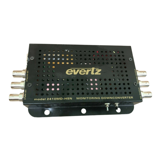
2410MD Monitoring Down Converter INSTALLATION The 2410MD-HSN is a compact module that has six BNC connectors and a 9 pin Female D connector serial port for firmware upgrades. Figure 2-1: 2410MD-HSN Module 2.1. POWER The 2410MD-HSN comes with an auto-ranging DC voltage adapter that automatically senses the input voltage. -
Page 9: Firmware Upgrade Port
The COM connector is a female 9 pin D connector used for connecting a computer to upload firmware to the 2410MD-HSN. Table 2-1 shows the pinout of the male high density DB-15 connector. See section 6 for information on upgrading the firmware in the 2410MD-HSN. -
Page 10: Specifications
2410MD Monitoring Down Converter SPECIFICATIONS 3.1. HD SERIAL VIDEO INPUT Standard: 1.485 Gb/sec SMPTE 292M – autodetect Connector: BNC per IEC 60169-8 Amendment Equalization: Automatic to 65m @ 1.5Gb/s with Belden 1694 or equivalent cable Common Name Pixels / Frame Rate Progressive SMPTE Active Lines... -
Page 11: Analog Video Outputs
Complies with FCC regulations for class A devices. Complies with EU EMC directive. 3.7. PHYSICAL Dimensions: 6“ L x 4” W x 1” H (152mm L x 114mm W x 25mm H) Weight: 0.5 lbs. (0.28 Kg) 2410MD-HSN-5 Revision 1.2.3... -
Page 12: Status Led's
USER CONTROLS The 2410MD-HSN is equipped with a 4 position DIP switch, located on one end of the unit, to allow the user to select various down converted output formats. On later units there is also a toggle switch and pushbutton on the side of the units, which are used to top control an on screen display menu. -
Page 13: Selecting The Downconverter Aspect Ratio
DIP switch 4 is used to select whether the NTSC Setup Pedestal will be applied on the Analog Output. The NTSC setup pedestal should not be present when operating in Japan. DIP 4 Output Pedestal Pedestal inserted No pedestal Table 5-4: Analog Output Video NTSC Pedestal Settings 2410MD-HSN-7 Revision 1.2.3... -
Page 14: Configuring The 2410Md-Hsn Using The On Screen Menu
CONFIGURING THE 2410MD-HSN USING THE ON SCREEN MENU An On screen menu (OSD) is used to configure several of the 2410MD-HSN’s parameters. The three position, return to center, toggle switch and momentary pushbutton located on the side of the unit are used to navigate the OSD setup menus and configure the cards various controls. -
Page 15: Setting The On Screen Marker Type
With this control, you can select the opacity of the On screen markers. 25 percent 50 percent 75 percent 100 percent 6.4. SETTING THE ASPECT RATIO Aspect Ratio With this control, you can select the aspect ratio of the downconverted picture. Letterbox 4:3 Center Crop 4:3 Squeeze 2410MD-HSN-9 Revision 1.2.3... -
Page 16: Upgrading The 2410Md-Hsn Firmware
Flow Control None 4. Apply power to the 2410MD-HSN. After the unit powers up, a banner with the boot code version information should appear in the terminal window. The cursor to the right of the word “BOOT>” should be spinning for about 5 seconds then the unit will continue to boot. -
Page 17: 7.2.3. Part 3 - Uploading The New Firmware
11. Upload the “*.bin” file supplied using the X-Modem transfer protocol of your terminal program. If you do not start the upload within 10 minutes the 2410MD-HSN Boot code will time out. You can restart the upgrade process by removing and reinstalling the module. - Page 18 2410MD Monitoring Down Converter This page left intentionally blank 2410MD-12 Revision 1.2.3...
Need help?
Do you have a question about the 2410MD-HSN and is the answer not in the manual?
Questions and answers