
Related Manuals for Satec BFM II EM


Summary of Contents for Satec BFM II EM
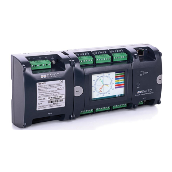
- Page 1 Branch Feeder Monitor BFM II EM and DFR OPERATION and INSTALLATION MANUAL BG0588 Rev. A10...
- Page 2 REVISION HISTORY Nov 2015 Initial guide Jan 2016 Updated guide Mar 2016 Electrical Installation load numbering Jun 2016 Sealing the BFM II Oct 2016 UL comments and Marking Label update Dec 2016 9RO module, update HMI user guide Jan 2017 Added 4AI module Added wiring connections: 4LL3 (delta) and 3OP2/3OP3 (open delta) Number of records for each log type is updated...
- Page 3 36 months from the date of production. This warranty is on a return to factory basis. This warranty is only applicable to SATEC instruments using HACS SATEC current transformers. The manufacturer does not accept liability for any damage caused by instrument malfunction.
- Page 4 WARNING Read the instructions in this manual before performing installation and take note of the following precautions: BFM II is intended for measurements performed in building and industrial installations, relating to measurement category III (UL61010-1 3 ed.), pollution degree 2. ...
-
Page 5: Table Of Contents
Table of Contents Chapter 1 General Information ........12 Firmware Versions................13 Labeling ..................13 Chapter 2 Installation ............15 Mechanical Installation ..............15 Dimensions .................. 16 Electrical Installation ..............20 Connecting the wires ............... 21 Typical Installation ................22 Installation with Auxiliary Power Supply .......... - Page 6 Chapter 3 BFM II Graphical Display Operations ....46 Startup Diagnostics ..............46 Display Features ................47 Submeter Displays ................47 Display Update ................47 Auto Return ..................47 Auto Scroll ..................47 Backlight ..................47 Navigation Buttons ............... 48 Measurements Views ...............
- Page 7 Using Alarm/Control Setpoints ............86 Using Counters ................88 Configuring the Fault Recorder ............89 Display Setup ................. 90 Configuring Billing Energy and TOU Registers ......93 Setting up Total and Tariff Registers ..........93 Configuring the Daily Tariff Schedule ..........94 Configuring the Season Tariff Schedule ..........
- Page 8 Appendix B HACS Connection Template ...... 112 Upgrading BFM136 to BFM II (236) ..........114 Appendix C Parameters for Data Monitoring and Logging Appendix D Setpoints Triggers and Actions ....120 Setpoint Triggers ................120 Setpoint Actions ................120 Appendix E Data Scales ..........121 Appendix F Device Diagnostic Codes ......
- Page 9 This package contains BFM II instrument BFM II optional modules BFM II extended instrument BFM II Branch Feeder Monitor...
- Page 10 HACS - 800A – (split core) Internal Hole 43x33 mm (1.69x1.13”) 80x50 mm (3.1x1.9”) HACS – SATEC proprietary current sensor for direct connection applications (Low Voltage) RS5 – SATEC proprietary current sensor for transformer operated applications (Medium-High Voltage) BFM II Branch Feeder Monitor...
- Page 11 Designator Label Sets HACS designator label set - to attach to the HACS Cable designator tie-marker BFM II Branch Feeder Monitor...
-
Page 12: Chapter 1 General Information
Chapter 1 General Information Chapter 1 General Information The BFM II is a 3-phase, multi-channel, modular multi-function energy meter suitable for use in single-phase and multi-phase electrical networks. Meter highlights Multi-channel submetering – up to 54 single-phase or 27 two-phase or 18 three-phase submeters in a single device. -
Page 13: Firmware Versions
Mac. Ad. BL611 REV.C USE ONLY WITH THE SUPPLIED USE ONLY WITH THE SUPPLIED USE ONLY WITH THE SUPPLIED SATEC HACS SATEC HACS-RS5 SATEC HACS (current tra ns forme r) (current tra ns forme r) (current tra ns forme r) - Page 14 Chapter 1 General Information Figure 1-2 DFR Device label BFM II Branch Feeder Monitor...
-
Page 15: Chapter 2 Installation
Chapter 2 Installation Mechanical Installation Chapter 2 Installation Mechanical Installation Follow instructions below to assemble the BFM II modules: BFM II Branch Feeder Monitor... -
Page 16: Dimensions
Chapter 2 I n s t a l l a t i o n Dimensions Dimensions Figure 2-1a BFM II Front View dimensions, DIN Rail and Wall mount – 18 channels Figure 2-1b BFM II Front View dimensions – 24 channels BFM II Branch Feeder Monitor... - Page 17 Chapter 2 Installation Dimensions Figure 2-1c BFM II Front View dimensions – 30 channels Figure 2-1d BFM II Front View dimensions – 36 channels Figure 2-1e BFM II Front View dimensions – 42 channels BFM II Branch Feeder Monitor...
- Page 18 Chapter 2 I n s t a l l a t i o n Dimensions Figure 2-1f BFM II Front View dimensions – 54 channels Figure 2-1g BFM II Rear and Side Views dimensions – 36 channels Figure 2-1h BFM II Optional Modules dimensions BFM II Branch Feeder Monitor...
- Page 19 Chapter 2 Installation Dimensions Figure 2-2 Single HACS (100A) dimensions BFM II Branch Feeder Monitor...
-
Page 20: Electrical Installation
Chapter 2 I n s t a l l a t i o n Electrical Installation Electrical Installation BFM II offers maximum flexibility of current connections by using the variety of HACS options and by wiring any HACS to any current input of the device. The following drawings present applications serviced by the BFM II. -
Page 21: Connecting The Wires
Connecting the wires All conductors must be stranded copper. All conductors and insulation systems and crimped devices must be appropriate for the application. SATEC recommends crimped ferrules on stranded wire. Tighten the screws on the high voltage terminal block to 0.5 Newton-meter (5 inch-pounds) of torque. -
Page 22: Typical Installation
Chapter 2 I n s t a l l a t i o n Electrical Installation Typical Installation 4LN3 wiring connection 4-wire 3-element Wye connection using 3 CTs with Neutral phase. Figure 2-3a Typical Electrical Installation – 6 x 3 phase current input channels wiring – 4LN3 BFM II Branch Feeder Monitor... - Page 23 Chapter 2 Installation Electrical Installation 4LL3 wiring connection 4-wire 3-element Delta direct connection using 3 CTs Figure 2-3b Typical Electrical Installation – 6 x 3 phase current input channels wiring – 4LL3 BFM II Branch Feeder Monitor...
- Page 24 Chapter 2 I n s t a l l a t i o n Electrical Installation 3OP2 wiring connection 3-wire 2-element Open Delta connection using 2PTs and 2CTs. The maximum input voltage from the PT secondary shall not exceed 250V Figure 2-3c Typical Electrical Installation –...
- Page 25 Chapter 2 Installation Electrical Installation 3OP3 wiring connection 3-wire 3-element Open Delta connection using 2PTs and 3CTs The maximum input voltage from the PT secondary shall not exceed 250V Figure 2-3d Typical Electrical Installation – 6 x 3 phase current input channels wiring – 3OP3 BFM II Branch Feeder Monitor...
-
Page 26: Installation With Auxiliary Power Supply
Chapter 2 I n s t a l l a t i o n Electrical Installation Maximum submeters wiring connection Figure 2-4a Typical Electrical Installation – 18 x 3 phase current input channels wiring Installation with Auxiliary Power Supply Figure 2-4b Typical Electrical Installation – 12 x 3 phase current input channels wiring with AC/DC Auxiliary Power Supply For operating temperature range of -20C to 60C, the Aux. - Page 27 Chapter 2 Installation Electrical Installation Figure 2-5 Single HACS wiring and labeling USE ONLY WITH SUPPLIED BFM CURRENT TRANSFORMERS! Connect the wires to the + and - inlets according to the following polarity colors: Polarity Solid Core HACS Split Core HACS Split Core RS5 secondary secondary...
- Page 28 Chapter 2 I n s t a l l a t i o n Electrical Installation Put the HACS/RS5 label stickers I7, I8, and I9 directly on HACSs/RS5s to indicate that these HACSs/RS5s will be associated with the device current terminals I7, I8, and I9.
-
Page 29: Sealing The Bfm Ii
Chapter 2 Installation Electrical Installation Sealing the BFM II Every instrument external connections as Voltage Inputs terminals, Current Inputs terminals, COM1 terminal, USB and ETH connectors, can be sealed to avoid non- qualified technician to access these connections. It is recommended to seal the BFM II after wiring the instrument. To seal the instrument follow the instructions above: Remove all terminal/connectors clear covers Wire the terminal connections accordingly... - Page 30 Chapter 2 I n s t a l l a t i o n Electrical Installation Attach the security seal cable lock to the terminals clear covers BFM II Branch Feeder Monitor...
-
Page 31: Communications
Figure 2-7a RS-485 3-wire connection – COM1 RS-422/485 Connection – COM2 (optional CELLULAR add-on module) Figure 2-7b RS-485 3-wire connection – COM2 WiFi, Bacnet communication modules are not available – future options, contact SATEC for more details. BFM II Branch Feeder Monitor... -
Page 32: Network Communication Ports
Chapter 2 I n s t a l l a t i o n Communications Network Communication ports The BFM II provides an Ethernet connection as standard and optional public wireless network using the optional add-on CELLULAR module. Both networks can operate simultaneously. Ethernet Connection 10/100Base T (standard) BFM II provides one 10/100TX Ethernet communication port in the MCM... -
Page 33: Usb Connection (Standard)
Chapter 2 Installation Communications USB Connection (standard) BFM II MCM module provides one galvanic isolated USB Device communication port, to be connected to a personal computer to run PAS figure 2-10 configuration tool, as shown in Figure 2-10 USB connection – Type A male BFM II Branch Feeder Monitor... -
Page 34: Input/Output
Chapter 2 I n s t a l l a t i o n Input/Output Input/Output Digital Inputs 9 or 18 optically isolated digital inputs in one digital input module (9/18DI) are provided for status monitoring and external synchronization of power demand period and time. - Page 35 Chapter 2 Installation Input/Output 2-12 . Each relay contact can be controlled using MODBUS command through any BFM II communication ports. Up to two 9RO modules can be installed in the BFM II BFM II Branch Feeder Monitor...
-
Page 36: Analog Inputs
Chapter 2 I n s t a l l a t i o n Input/Output Analog Inputs 4 optically isolated analog inputs in one analog input module (4AI) are provided for sensor monitoring such temperature sensors, fuel level measurement, etc. … Current input options are: 0-20 mA and 4-20 mA, 0-1 mA and ±1 mA, as shown in Figure 2-12 The scan time for regular analog inputs is 2 cycles (32 ms at @ 60Hz and 40 ms... -
Page 37: Installing The Battery Backup
Chapter 2 Installation Installing the Battery backup Installing the Battery backup The BFM II is packed without battery; therefore it must be installed by the installer during the BFM II installation. After turning "ON" the BFM II power supply for the first time following battery installation, the BFM II initialization process duration may take about 7 minutes, while regular BFM II initialization process duration takes 40 seconds... -
Page 38: Controls And Indicators
Chapter 2 I n s t a l l a t i o n Controls and Indicators Controls and Indicators Figure 2-12 BFM II Front View Indicator LEDs The CPU/Energy Pulse LED, flashing green means CPU LED shows that the device is in initialization process after RESET or POWER ON. -
Page 39: Communicating With The Bfm Ii
Chapter 2 Installation Communicating with the BFM II Communicating with the BFM II Communication with the BFM II can be established independently and simultaneously through any communications port using the support PAS program supplied with the device or user application software. All communication ports are slave ports and have factory-preset parameters, such as baud rate, data format, and communications protocol that can be easily changed whenever desired. -
Page 40: Ethernet Port (Standard)
Chapter 2 I n s t a l l a t i o n Communicating with the BFM Ethernet Port (standard) A 10/100Base-T Ethernet port provides a direct connection of the BFM II to a local area network through the TCP/IP protocols. The device has three onboard TCP servers configured for the Modbus/TCP (at TCP port 502), DNP3.0/TCP (at TCP port 20000) and IEC 60870-5-104 (at TCP port 2404) communications. -
Page 41: Device Settings
Chapter 2 Installation Device Settings PAS can communicate with the devices through any BFM II port using the MODBUS RTU, MODBUS ASCII and DNP3.0 protocols. For information on installing and using PAS, see Chapter 4 “Using PAS”. Device Settings Before operating your BFM II, provide the device with information about your particular environment. -
Page 42: Submeter System
Chapter 2 I n s t a l l a t i o n Device Settings Submeter System The BFM II provides up to 54 submeters with separate measurement and energy registers. Each submeter can service current inputs dedicated to a particular consumer (metering submeter) or be used as a Totalization meter for automatic Totalization of energy from different sub-consumers (Totalization submeter). -
Page 43: Energy/Tou System
Chapter 2 Installation Device Settings Energy/TOU System The BFM II provides 8 separate billing energy (total/summary and parallel tariff and maximum demand) registers for each individual submeter. Each register can be linked to any internal energy source or another submeter. The first billing register in your meter is linked to the kWh accumulator by default. -
Page 44: Billing Data Recording And Load Profiling
Chapter 2 I n s t a l l a t i o n Device Diagnostics Parameter Label I2 Odd/even-harmonic distortion I2 %HD1 - I2 % HD25 I3 Odd/even-harmonic distortion I3 %HD1 - I3 % HD25 Symmetrical Components Positive-sequence voltage V PSEQ Negative-sequence voltage V NSEQ... -
Page 45: Billing Data Display
Chapter 2 Installation Device Diagnostics When the lithium battery voltage drops below the minimum allowed level, it is indicated in the device diagnostics. In this event, the battery should be checked and replaced if required. Billing Data Display The BFM II display submeter indicates billing energy, maximum demand and cumulative maximum demand registers for the present billing period and for three previous billing periods. -
Page 46: Chapter 3 Bfm Ii Graphical Display Operations
Chapter 3 I n s t a l l a t i o n Startup Diagnostics Chapter 3 BFM II Graphical Display Operations Startup Diagnostics After applying power to the meter, a start-up message is displayed for one second “Initialization in progress …” indicates a normal power-up sequence. -
Page 47: Display Features
Chapter 3 BFM II Graphical Display Operations Display Features Display Features The multifunctional TFT Graphical LCD Display Module (GDM) with backlight allows easy read outs of the measurement parameters both in the dark and under sunlight. The menu-driven multi-page display allows viewing numerous measurement parameters by scrolling through display screens and pages using Touch Panel buttons. -
Page 48: Navigation Buttons
Chapter 3 I n s t a l l a t i o n Navigation Buttons Navigation Buttons The BFM II GDM is equipped with Touch Panel (TP) buttons. The TP buttons allow you to navigate through device setup menus and to change the device settings. The BFM II display has several multi-page screens for viewing numerous measurement parameters shown in the following screens. - Page 49 Chapter 3 BFM II Graphical Display Operations Navigation Buttons Voltages views Pressing “Voltages” button, shows three phase voltage measurements with minimum maximum value from last slide window, first “Voltages” page shows Line-to- Neutral phase voltage. This screen is also the default screen appearing after Power UP or Instrument Reset This page also shows status bar including current date and time, mode status (NORMAL or TEST), tariff no.,...
- Page 50 Chapter 3 I n s t a l l a t i o n Navigation Buttons Current views Pressing “Currents” will move to Min/Max and Max DMD screen menu. Pressing “Min./Max.” button, shows submeters Current consumption with min/max values. Pressing “PREV” or “NEXT” button will scroll over all submeters current measurement pages.
- Page 51 Chapter 3 BFM II Graphical Display Operations Navigation Buttons Powers and PF views Pressing “Powers & PF” button will move to Min/Max and Max DMD screen menu. Pressing “Min./Max.” button, shows total powers and PF measurements with min/max values. Pressing “SUBM” button, shows submeters current active and reactive powers and power factor.
-
Page 52: Device Control Views
Chapter 3 I n s t a l l a t i o n Navigation Buttons Device Control views The BFM II Device control display views permits to display instrument diagnostic status. It shows device diagnostic messages recorded as a result of the meter self- test diagnostics during start-up and operation. -
Page 53: Waveforms Views
Chapter 3 BFM II Graphical Display Operations Navigation Buttons Waveforms views The BFM II instrument waveforms menu displays the three-phase voltage and current channels waveforms, the represented current channels are the first three- phase current channels (I1-I3). The display is refreshed every second. Note: Harmonics display will be supported from BFM II phase II. -
Page 54: Instrument Setup
Chapter 3 I n s t a l l a t i o n Instrument Setup Instrument Setup The BFM II setup is menu-driven. To enter the setup menus, press the “Instrument” or “Display” setup buttons. The BFM II setup capability using the instrument interactive display is limited to user level setups only and only if “front panel security”... -
Page 55: General Setup
Parameters in light grey background are read only and cannot be changed from the front panel. Use PAS™, SATEC software configuration tool, to setup these parameters. The following table lists available setup options Parameter... - Page 56 Chapter 3 I n s t a l l a t i o n Instrument Setup Parameter Options Default Description Tariff Control Calendar Calendar Defines the tariff switching method (see “Tariff Control” Communication below). Tariff inputs D1…D8 Tariff Control The BFM II provides an unique tariff program for all device submeters, there are three options for switching tariff rates, can be setup using PAS SW tools only, see chapter 4 General Meter...
-
Page 57: Submeter Channel Assignments
Submeter Channel Assignments The Submeter Channels Assignments setup menu allows to setup submeter name only. To setup the CT primary value of the desired submeter according to the SATEC CT – HACS/RS5 rating, follow chapter General Meter Setup, Channel assignment... -
Page 58: Time Adjustment Setting
Chapter 3 I n s t a l l a t i o n Instrument Setup Parameter Options Default Description week of the month and DST end day of Sunday-Saturday Sunday weekday. By default, DST ends the week at 2:00 AM on the last Sunday in October of each year. - Page 59 Pressing COM1 button will show the current COM1 setup parameters. Parameters in light grey background are read only and cannot be changed from the front panel. Use PAS™, SATEC software configuration tool, to setup these parameters. Press Device Address Value field to change the protocol device address.
- Page 60 Communication Setup menu. Parameters in light grey background are read only and cannot be changed from the front panel. Use PAS™, SATEC software configuration tool, to setup these parameters. Press IP Address Value field to change the device IP address network.
-
Page 61: Reset Setup
Chapter 3 BFM II Graphical Display Operations Instrument Setup Reset Setup This menu allows you to reset maximum demands, data log, counters, TOU summary maximum demand and event logs. To enter the menu, select the Reset entry from the main menu, and then press the ENTER button. - Page 62 Chapter 3 I n s t a l l a t i o n Instrument Setup Reset Device Event Log To reset the Device Event Log press “Dev. Event Log” button Pressing “OK” button will clear the Event Log, and will return confirmation box.
-
Page 63: Display Info And Setup
Chapter 3 BFM II Graphical Display Operations Display Info and Setup Display Info and Setup Display Info This menu allows you to configure options for the BFM II display and to show Display factory info. To enter the menu, press the Display Setup button from the main menu. -
Page 64: Display Setup
Chapter 3 I n s t a l l a t i o n Display Info and Setup Display Setup The Display Setup menu allows you to configure the display language, sleep mode and brightness. Press the Display button to setup the main display parameters. -
Page 65: Customer Name
Chapter 3 BFM II Graphical Display Operations Display Info and Setup Customer Name The Customer Name menu allows you to determine the device Customer Name to appear on the BFM II GDM menu bar screen (bottom bar Pressing Customer Name button will provide an alpha numeric “qwerty” keyboard to enter the Customer Name. -
Page 66: Chapter 4 Using Pas™ Application Software
Chapter 4 I n s t a l l a t i o n Software Installation Chapter 4 Using PAS™ Application Software The support PAS software is a configuration and data acquisition tool that allows you to configure all of the BFM II features, monitor your meter on-line, retrieve recorded files and view log files. - Page 67 Chapter 4 Using PAS™ Application Software Software Installation Select “Install from a list or specific location” and click “Next”. Click “Browse”. Point to the “USB” folder located in the PAS installation directory and click “OK” BFM II Branch Feeder Monitor...
-
Page 68: Using Pas
Chapter 4 I n s t a l l a t i o n Using PAS Click “Next”. Click "Finish" to complete installation. The next time you power up the BFM II or connect it to your PC with the USB cable, Windows automatically launches the driver for your meter. - Page 69 Chapter 4 Using PAS™ Application Software Creating a new site for your Meter / Submeters From the “Look in” box, select the directory where a new database will be stored. By default, it will be the “Sites” directory. Type a site name for the submeter in the “File name”...
-
Page 70: Setting Up Communications
Chapter 4 I n s t a l l a t i o n Setting up Communications Setting up Communications You can communicate with your devices via a PC RS-232 serial port, a PC USB port, through the Internet, via either a local Ethernet, or a wireless CELLULAR (GPRS- 2G or 3G) Dial-Up connection. - Page 71 Chapter 4 Using PAS™ Application Software Setting up Communications In the Protocol box, select the same communications protocol as you have in your BFM II. The default protocol setting in the BFM II for all ports is Modbus RTU. The remaining settings in this dialog do not normally need to be changed. In the “Response Time-out”...
-
Page 72: Communicating Through The Internet
Chapter 4 I n s t a l l a t i o n Setting up Communications Communicating through the Internet If you are communicating via the Ethernet, define the IP address of your BFM II on the network. On the Instrument Setup tab, select Internet Site. Click on the Connection tab. -
Page 73: Communicating Through A Usb
Chapter 4 Using PAS™ Application Software Setting up Communications In the “Protocol” box, select the communications protocol for the BFM II GPRS TCP port. The host port is set automatically as you select the protocol. Select “Modbus RTU/TCP” for Modbus/TCP, or “DNP3” for DNP3/TCP. In the “Wait for answer”... -
Page 74: Preparing Setups
Chapter 4 I n s t a l l a t i o n Preparing Setups Preparing Setups PAS allows you to prepare setup data for your BFM II off-line without the need to have it connected to your PC. To prepare a setup for your meter: Select the device site from the list box on the PAS toolbar. -
Page 75: Uploading Setups
Chapter 4 Using PAS™ Application Software Authorization of the submeters and store them to its site database, select the submeter site from the list box on the toolbar, and then click Download to all Submeters on the Meter Setup menu. Uploading Setups To upload the setups from the submeter to the site database, check the On-line button on the PAS toolbar, select the submeter site from the list box on the toolbar,... -
Page 76: Setting Up The Local Network
Chapter 4 I n s t a l l a t i o n Changing Port Settings Note When using the expertpower client (see Configuring expertpower Client), submeter address 99 on the Ethernet port is reserved for the BFM II router and must not fall inside the range of the submeter addresses for this port. -
Page 77: Setting Up Sntp Client
The BFM II has an embedded expertpower client that provides communications with the eXpertPower server – the SATEC proprietary Internet services. Connections to the eXpertPower server are handled on a periodic basis. To enter the Setup dialog, select the site from the list box on the PAS toolbar, select Communication Setup from the Meter Setup menu, and then click the expertpower Client Setup tab. - Page 78 Chapter 4 I n s t a l l a t i o n Changing Port Settings The following table lists available options. Refer to your eXpertPower service provider for the correct eXpertPower settings. Parameter Options Default Description The IP address of the XPW Server IP Address 207.232.60.18 eXpertPower server...
-
Page 79: General Meter Setup
Chapter 4 Using PAS™ Application Software General Meter Setup General Meter Setup This section describes how to configure the BFM II for your particular environment and application using PAS. Basic Meter Setup Before operating your meter, provide the device with basic information about your electrical network. - Page 80 Chapter 4 I n s t a l l a t i o n General Meter Setup Parameter Options Default Description Energy roll value, kWh 100000.0 kWh 100000000.0 The value at which energy counters roll over to zero 1000000.0 kWh 10000000.0 kWh 100000000.0 kWh Energy LED pulse rate,...
-
Page 81: Channel Assignments
Chapter 4 Using PAS™ Application Software General Meter Setup Channel Assignments The Channel Assignments setup allows you to link the device current terminals to submeters so they can monitor them. Additionally, this setup allows you to specify the primary current rating of the current transformers connected to the device terminals. -
Page 82: Transformer Correction
General Meter Setup Transformer Correction Transformer correction allows you to compensate ratio and phase angle inaccuracies of the user voltage transformers and SATEC current sensors (HACS) instrument. If you use standard current transformers listed in the last table column, select a transformer type to preset the transformer ratio correction factor and phase angle error to their typical values. -
Page 83: Local Settings
Chapter 4 Using PAS™ Application Software General Meter Setup Local Settings The Local Settings setup allows you to specify your time zone and daylight saving time options. To configure the time zone options for your device, select the device site from the list box on the PAS toolbar, select General Setup from the Meter Setup menu, and then click on the Local Settings tab. -
Page 84: Using Digital Inputs
Chapter 4 I n s t a l l a t i o n General Meter Setup Using Digital Inputs The BFM II supports up to four expansion Digital Input (DI) modules with a total of 72 digital inputs (DI1 to DI72). I/O numbers are automatically assigned to the inputs in the order of connection when the device is powered up. -
Page 85: Using Analog Inputs
Chapter 4 Using PAS™ Application Software General Meter Setup Using Analog Inputs The BFM II can be equipped with up to three plug-in 4-channel Analog Input (4AI) modules. I/O numbers are automatically assigned to the analog inputs in the order of connection when the device is powered up. -
Page 86: Using Alarm/Control Setpoints
Chapter 4 I n s t a l l a t i o n General Meter Setup is shown in the picture above for the 0-20 mA analog inputs. Each of the scales operates independently. Scaling ±1mA Analog Inputs When programming engineering scales for directional ±1mA analog inputs, you should provide only the engineering scale for the +1 mA input current. - Page 87 Chapter 4 Using PAS™ Application Software General Meter Setup The following table describes the setpoint options. Option Range Description Appendix D Trigger The trigger parameter that is used as an argument in parameter the logical expression Operate limit The threshold (in primary units) at which the conditional expression would be evaluated to true.
-
Page 88: Using Counters
Chapter 4 I n s t a l l a t i o n General Meter Setup Using Counters The BFM II has 72 nine-digit signed counters that count different events. Each counter is independently linked to any digital input and count input pulses with a programmable scale factor. -
Page 89: Configuring The Fault Recorder
Chapter 4 Using PAS™ Application Software General Meter Setup Configuring the Fault Recorder The Fault recorder automatically records all fault events to the Fault log file. It can be triggered via the embedded fault detector, or externally through any of the 48 digital inputs. -
Page 90: Display Setup
Chapter 4 I n s t a l l a t i o n General Meter Setup Option Range Default Description 1-cycle RMS Plot Log Enabled Checked Unchecked Enables concurrent RMS trace plot to the data log file while the fault event continues Unchecked Max. - Page 91 Chapter 4 Using PAS™ Application Software General Meter Setup The Display Setup consists of Displays Options parameters Displays setup menus. The available display options are listed in the table below. Display Operations in Chapter 3 for more information on display functionality and configuring display options.
- Page 92 Chapter 4 I n s t a l l a t i o n General Meter Setup Display Label Parameter Options Default Description Default Page Default 1/2 – 1/10 Specifies the default Page 2/1 – 2/10 … display/page. If a page is not 12/1-12/10 available in present mode, the following available page will be...
-
Page 93: Configuring Billing Energy And Tou Registers
Chapter 4 Using PAS™ Application Software Configuring Billing Energy and TOU Registers Configuring Billing Energy and TOU Registers The BFM II provides eight total/summary energy and eight parallel tariff energy and maximum demand registers for each individual submeter. The registers can be linked to any internal energy source or to another submeter. -
Page 94: Configuring The Daily Tariff Schedule
Chapter 4 I n s t a l l a t i o n Configuring Billing Energy and TOU Registers Parameter Options Default Description Billing/TOU Registers Sum Profile Unchecked Unchecked Enables daily profiling for summary registers (total of all tariffs). Automatically Checked set when profiling is enabled. -
Page 95: Configuring The Season Tariff Schedule
Chapter 4 Using PAS™ Application Software Configuring Data Recorders To configure your daily profiles: Select the desired season and day type. Select the start time for each tariff change point and the corresponding active tariff number. Repeat the setup for all active profiles. The first tariff change point is fixed at 00:00 hours, and the last tariff change you specified will be in use until 00:00 hours on the next day. - Page 96 Chapter 4 I n s t a l l a t i o n Configuring Data Recorders organized as a wrap-around file that needs not to be cleared explicitly though it can be done via PAS (see Clearing Maximum Demands and Log Files).
-
Page 97: Remote Device Control
Chapter 4 Using PAS™ Application Software Remote Device Control Remote Device Control This section describes some online operations on the BFM II you can perform through PAS. To access device control options you should have your device online. DFR Data Recorders For DFR there are additional files per SM: ... - Page 98 Chapter 4 I n s t a l l a t i o n Remote Device Control To select the channels, click on the “Channels” button, check the boxes for channels to be recorded, and then click OK. Save your waveform setup to the site database, and send it to the device.
-
Page 99: Viewing And Clearing Device Diagnostics
Chapter 4 Using PAS™ Application Software Remote Device Control No. Parameter No. Parameter kWh Import V1 Demand kWh Export V2 Demand kvarh Import V3 Demand kvarh Export kVAh Factory Preset Fault Log Data log #13 is factory preset for RMS trending on the fault events and are intended for the use with the Fault recorder. -
Page 100: Updating The Clock
Chapter 4 I n s t a l l a t i o n Remote Device Control Updating the Clock To update the RTC clock in your device, select a site with base device address from the list box on the toolbar, check the On-line button on the toolbar, and then select RTC from the Monitor menu. -
Page 101: Administration
Chapter 4 Using PAS™ Application Software Administration Administration PAS allows you to remotely change the password or network security in your BFM II . Use the device base address to access your device. To change the password, select a device site from the list box on the PAS toolbar, check the On-line button, click Administration from the monitor menu, and then select Change Password. -
Page 102: Upgrading Device Firmware
Chapter 4 I n s t a l l a t i o n Upgrading Device Firmware Upgrading Device Firmware Your meter has upgradeable firmware. If you need to upgrade your device, you can download a new firmware file to the meter through PAS. Firmware can be downloaded through any communication port. -
Page 103: Data Monitoring
Chapter 4 Using PAS™ Application Software Data Monitoring Wait until PAS completes upgrading your device. It would take about 3-4 minutes at 115,200 bps to download the file to the device. After upgrading firmware is completed, the device restarts. If the meter is connected to your PC through the modem, communications can be temporarily lost and you may need to wait until PAS restores a connection with your device. -
Page 104: Retrieving Log Files
Chapter 4 I n s t a l l a t i o n Data Monitoring Retrieving Log Files Using PAS, you can retrieve the event and data log files from the BFM II submeters and save them to files on your PC in the MS Access database format. Historical data is uploaded on demand any time you need it, or periodically through the Upload Scheduler that retrieves data automatically on a predefined schedule, for example, daily, weekly or monthly. - Page 105 Chapter 4 Using PAS™ Application Software Data Monitoring Daily profile tables for energy and maximum demand registers are named as shown in the following picture. The following picture shows an example of energy profile data readings. BFM II Branch Feeder Monitor...
-
Page 106: Appendix A Technical Specifications
Appendix A T E C H N I C A L S P E C I F I C A T I O N S Appendix A Technical Specifications Environmental Conditions Operating Temperature (accuracy): -25°C to 60°C (-13°F to 140°F) Storage Temperature: -40°C to 85°C (-40°F to 185°F) Humidity: 0 to 95% non-condensing Altitude ≤... -
Page 107: Ac Current Inputs
AC Current Inputs: Standard: I1 – I54 – 40mA maximum input channel, HACS model Input via SATEC HACS 100A to 3000A with 40mA secondary Operating range: maximum continuous 120% I max: 120A for HACS 100A (Primary current) Nominal measured Current: 15A RMS for HACS 100A (Primary current) Maximum measured Current: 100A RMS for HACS 100A (Primary current) Burden: <... -
Page 108: Analog Inputs - 4 Inputs (Up To 4 Modules)
Appendix A T E C H N I C A L S P E C I F I C A T I O N S Analog Inputs – 4 Inputs (up to 4 Modules) 4 Analog Inputs: Ranges (upon order): 1 mA (100% overload) 0-20 mA 4-20 mA... -
Page 109: Log Memory
Appendix A T E C H N I C A L S P E C I F I C A T I O N S Log Memory Standard onboard memory: 250 Mbytes. Graphical Display Module - optional 3.5 Inch Touch-Panel LCD graphic TFT display Resolution: 320 x 240 Operating temperature: -20°C - +70 °C Communication:... -
Page 110: Standards Specifications
Appendix A T E C H N I C A L S P E C I F I C A T I O N S Standards Specifications EMC per IEC 62052-11, IEC 62053-22, ANSI C12.1 and ANSI C12.20 IEC61000-4-2: Electrostatic discharge, 15kV/8kV – air/contact IEC61000-4-3: Electromagnetic RF Fields, 10V/m @ 80MHz –... -
Page 111: Measurement Specifications
Appendix A T E C H N I C A L S P E C I F I C A T I O N S Measurement Specifications Parameter Full Scale @ Input Accuracy Range Range % Reading % FS Conditions Voltage = 120V 0.05... -
Page 112: Appendix B Hacs Connection Template
Appendix B H A C S C O N N E C T I O N T E M P L A T E Appendix B HACS Connection Template Use the following table to memorize your input assignments and wiring connections for sub-consumers. - Page 113 Appendix B H A C S C O N N E C T I O N T E M P L A T E Customer / Site name: Installation Date: Sub-consumer Input # Wire Color Cable# Phase BFM II Branch Feeder Monitor...
-
Page 114: Upgrading Bfm136 To Bfm Ii (236)
Appendix B H A C S C O N N E C T I O N T E M P L A T E Upgrading BFM136 to BFM II (236) The fact the BFM II is a modular device in terms of channels capacity, the channels numbering differ from the BFM 136, and the following table can be used to cross-reference the BFM136 installations with BFM II installation. -
Page 115: Logging
Appendix C P A R A M E T E R S F O R D A T A M O N I T O R I N G A N D L O G G I N G Appendix C Parameters for Data Monitoring and Logging The following table lists parameters measured by the meter that are available for... - Page 116 Appendix C P A R A M E T E R S F O R D A T A M O N I T O R I N G A N D L O G G I N G Designation Description kvar Total kvar...
- Page 117 Appendix C P A R A M E T E R S F O R D A T A M O N I T O R I N G A N D L O G G I N G Designation Description SUM REG8 Summary energy register #8...
- Page 118 Appendix C P A R A M E T E R S F O R D A T A M O N I T O R I N G A N D L O G G I N G Designation Description …...
- Page 119 Appendix C P A R A M E T E R S F O R D A T A M O N I T O R I N G A N D L O G G I N G Designation Description HARMONICS 1-second average 1...
-
Page 120: Appendix D Setpoints Triggers And Actions
Appendix D S E T P O I N T S T R I G G E R S A N D A C T I O N S Appendix D Setpoints Triggers and Actions Setpoint Triggers Designation Description NONE None (condition is not active) MINUTE INTERVAL Minute intervals (10, 15, 30, 60 min) synchronized... -
Page 121: Appendix E Data Scales
Appendix E D A T A S C A L E S Appendix E Data Scales The maximum values for volts, amps and power in the BFM II setup and in communications are limited by the voltage and current scale settings. See Basic Meter Setup in Chapter 4 on how to change the voltage scale in your meter. -
Page 122: Appendix F Device Diagnostic Codes
Appendix F D E V I C E D I A G N O S T I C C O D E S Appendix F Device Diagnostic Codes Diagnostic Display Description Reason Code Message RAM/Data fault RAM/Data error Hardware failure Hardware watchdog Watchdog reset Hardware failure...
Need help?
Do you have a question about the BFM II EM and is the answer not in the manual?
Questions and answers