Sign In
Upload
Manuals
Brands
Satec Manuals
Measuring Instruments
BFM II EM
Satec BFM II EM Manuals
Manuals and User Guides for Satec BFM II EM. We have
1
Satec BFM II EM manual available for free PDF download: Operation And Installation Manual
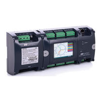
Satec BFM II EM Operation And Installation Manual (122 pages)
Branch Feeder Monitor
Brand:
Satec
| Category:
Measuring Instruments
| Size: 8 MB
Table of Contents
Table of Contents
5
Chapter 1 General Information
12
Firmware Versions
13
Labeling
13
Chapter 2 Installation
15
Mechanical Installation
15
Dimensions
16
Electrical Installation
20
Connecting the Wires
21
Typical Installation
22
Installation with Auxiliary Power Supply
26
Sealing the BFM II
29
Communications
31
Serial Communication Ports
31
Network Communication Ports
32
USB Connection (Standard)
33
Input/Output
34
Digital Inputs
34
Relay Outputs
34
Analog Inputs
36
Installing the Battery Backup
37
Controls and Indicators
38
Indicator Leds
38
Energy Pulse LED
38
Front Panel Display
38
Communicating with the BFM II
39
COM1 and COM3 (Standard), COM2 (Optional) Serial Communications
39
COM4 Port (Optional)
39
USB Port (Standard)
39
Ethernet Port (Standard)
40
Wireless Ethernet Port - Wifi (Optional)
40
CELLULAR Port (Optional)
40
Using the GDM (Optional)
40
Using PAS
40
Device Settings
41
Meter Security
41
Submeter System
42
Submeter Addressing
42
Basic Device Settings
42
Energy/Tou System
43
Tariff Rates
43
Fault Recording
43
Harmonic Measurements
43
Billing Data Recording and Load Profiling
44
Device Diagnostics
44
Monitoring Meter Batteries
44
Billing Data Display
45
Chapter 3 BFM II Graphical Display Operations
46
Startup Diagnostics
46
Display Features
47
Submeter Displays
47
Display Update
47
Auto Return
47
Auto Scroll
47
Backlight
47
Navigation Buttons
48
Measurements Views
48
Device Control Views
52
Instrument Info Views
52
Waveforms Views
53
Phasor Views
53
Logs Views
53
Instrument Setup
54
Entering a Password
54
Viewing and Changing Instrument Setup Parameters
54
General Setup
55
Submeter Channel Assignments
57
Transformer Correction
57
Local Setting
57
Time Adjustment Setting
58
Communication Setup
58
Reset Setup
61
Display Info and Setup
63
Display Info
63
Display Setup
64
Customer Name
65
Chapter 4 Using PAS™ Application Software
66
Software Installation
66
Installing PAS™ Software
66
Installing the USB Driver
66
Using PAS
68
Creating a New Site for Your Meter / Submeters
68
Setting up Communications
70
Communicating through a Serial Port
70
Communicating through the Internet
72
Communicating through a CELLULAR (2G/3G) Module
72
Communicating through a USB
73
Preparing Setups
74
Downloading Setups
74
Uploading Setups
75
Authorization
75
Changing Port Settings
75
Communication Ports Setup
75
Setting up the Local Network
76
Setting up Cellular - Public Network
76
Setting up SNTP Client
77
Configuring Expertpower Client
77
General Meter Setup
79
Basic Meter Setup
79
Channel Assignments
81
Transformer Correction
82
Local Settings
83
Using Digital Inputs
84
Using Analog Inputs
85
Using Alarm/Control Setpoints
86
Using Counters
88
Configuring the Fault Recorder
89
Display Setup
90
Configuring Billing Energy and TOU Registers
93
Setting up Total and Tariff Registers
93
Configuring the Daily Tariff Schedule
94
Configuring the Season Tariff Schedule
95
Configuring Data Recorders
95
Remote Device Control
97
DFR Data Recorders
97
Viewing and Clearing Device Diagnostics
99
Updating the Clock
100
Clearing Maximum Demands and Log Files
100
Administration
101
Upgrading Device Firmware
102
Data Monitoring
103
Viewing Real-Time Data
103
Retrieving Log Files
104
Appendix A Technical Specifications
106
Environmental Conditions
106
Construction
106
Overall Dimensions
106
Materials
106
Power Supply
106
Main Power Supply (Self-Energized PS)
106
Auxiliary Power Supply (Module)
106
Input Ratings
106
AC Voltage Inputs: V1, V2, V3, VN
106
AC Current Inputs
107
Plug-In I/O Ratings
107
Digital Inputs - 4DI/4DO (Future) or 9DI or 18DI (up to 4 Modules)
107
Relay Outputs - 9RO (up to 2 Modules)
107
Relay Outputs - 4DI/4DO (up to 4 Modules - Future)
107
Analog Inputs - 4 Inputs (up to 4 Modules)
108
Communication Ports
108
COM1 - Standard (MCM)
108
COM2 - Optional (Communication Module)
108
COM3 - Standard (MCM Display Communication Port)
108
USB Port - Standard (MCM)
108
Ethernet Port - Standard (MCM)
108
COM4 - CELLULAR - Optional (Communication Module)
108
Real-Time Clock
108
Log Memory
109
Graphical Display Module - Optional
109
Gdm
109
Standards Specifications
110
EMC Per IEC 62052-11, IEC 62053-22, ANSI C12.1 and ANSI C12.20
110
Safety
110
Insulation
110
Environment Conditions
110
Accuracy
110
Measurement Specifications
111
Appendix B HACS Connection Template
112
Upgrading BFM136 to BFM II (236)
114
Logging
115
Appendix D Setpoints Triggers and Actions
120
Setpoint Triggers
120
Setpoint Actions
120
Appendix E Data Scales
121
Appendix F Device Diagnostic Codes
122
Advertisement
Advertisement
Related Products
Satec BFM II DFR
Satec BFM 136
Satec C191HM
Satec EM132
Satec EM133
Satec EM133-SE
Satec EM235 Series
Satec expertmeter EM720
Satec expertmeter EM720T
Satec Expertmeter PM180
Satec Categories
Measuring Instruments
Control Unit
Cell Phone
Test Equipment
Data Loggers
More Satec Manuals
Login
Sign In
OR
Sign in with Facebook
Sign in with Google
Upload manual
Upload from disk
Upload from URL