
Related Manuals for Satec BFM 136


Summary of Contents for Satec BFM 136
- Page 1 Branch Feeder Monitor BFM 136 Installation and Operation Manual BG0394 Rev. A11 Branch Feeder Monitor 136_Installation Operation and Manual...
- Page 2 36 months from the date of production. This warranty is on a return to factory basis. This warranty is only applicable to SATEC instruments using HACS SATEC current transformers. The manufacturer does not accept liability for any damage caused by instrument malfunction.
- Page 3 WARNING Read the instructions in this manual before performing installation and take note of the following precautions: BFM136 is intended for measurements performed in building installations, relating to measurement category III (UL61010-1, 6.7.4). Ensure that all incoming AC power and other power sources are turned OFF before performing any work on the instrument.
- Page 4 Table of Contents Chapter 1 Information ....................8 Meter Highlights ...................... 8 Features ........................8 Labeling ....................... 9 1.2.1 Chapter 2 Installation ..................10 Mechanical Installation ..................10 Electrical Installation .....................13 Communications ....................16 Controls and Indicators ..................19 Indicator LEDs .................... 19 2.4.1 Energy Pulse LED ..................
- Page 5 Setting up Communications ..................38 Communicating through a Serial Port ............. 38 4.2.1 Communicating through the Internet ............. 39 4.2.2 Preparing Setups ....................39 Downloading Setups ..................40 4.3.1 Uploading Setups ..................40 4.3.2 Authorization ......................40 Changing Port Settings ..................41 Setting Up Communication Ports ..............41 4.5.1 Setting Up the Local Network ................
- Page 6 HACS - 100A – (solid core) Internal Hole HACS - 100A – (solid core) Internal Hole 16 23 mm (0.91") mm (0.63") HACS – SATEC proprietary current sensor for direct connection applications (Low Voltage) Branch Feeder Monitor 136_Installation Operation and Manual...
- Page 7 Designator Label Sets Branch Feeder Monitor 136_Installation Operation and Manual...
- Page 8 Chapter 1 Information Meter Highlights Information Chapter 1 The BFM136 is a 3-phase, multi-channel, multi-function energy meter suitable for use in single-phase and multi-phase electrical networks. Meter Highlights • Multi-channel submetering – up to 36 single-phase or 18 two-phase or 12 three-phase submeters in a single device.
- Page 9 Chapter 1 Information Features 1.2.1 Labeling Figure 1-1a Device label - Wye/Delta Wiring Configuration Figure 1-1b DFR label – Wye/Delta Wiring Configuration per NMI Standards Branch Feeder Monitor 136_Installation Operation and Manual...
- Page 10 Chapter 2 Installation Mechanical Installation Installation Chapter 2 Mechanical Installation Figure 2-1 BFM136 Dimensions Branch Feeder Monitor 136_Installation Operation and Manual...
- Page 11 Chapter 2 Installation Mechanical Installation Figure 2-2 Wall mounting Figure 2-3 DIN rail mounting Branch Feeder Monitor 136_Installation Operation and Manual...
- Page 12 Chapter 2 Installation Mechanical Installation Figure 2-4 Single HACS dimensions Branch Feeder Monitor 136_Installation Operation and Manual...
- Page 13 Chapter 2 Installation Electrical Installation Electrical Installation BFM136 offers maximum flexibility of current connections by using the variety of HACS options and by wiring any HACS to any current input of the device. The following drawings present applications serviced by the BFM136. Before installation ensure that all incoming power sources are shut OFF.
- Page 14 Chapter 2 Installation Electrical Installation Figure 2-5b Typical Electrical Installation – Delta Wiring Figure 2-6 Single HACS Wiring and Labeling Branch Feeder Monitor 136_Installation Operation and Manual...
- Page 15 Chapter 2 Installation Electrical Installation USE ONLY WITH SUPPLIED BFM CURRENT TRANSFORMERS! Connect the wires to the + and - inlets according to the following polarity colors: Polarity Solid Core HACS secondary Split Core HACS secondary WHITE ORANGE BLACK It is recommended to mark the cables and CTs with the supplied tie markers. HACS stickers I1 through I36 correspond to the BFM136 current inputs with matching labels.
- Page 16 Chapter 2 Installation Communications Communications Several communication options are available for the BFM136. RS485 RS485 RS485 RS232 NONE RS485 RS485 RS485 DIAL-UP MODEM TELEPHON ETHERNET RS485/422 Figure 2-8 Communication Options RS-485 Connection Figure 2-9 RS-485 2-wire connection BFM136 BFM136 BFM136 CONVERTER RS485/422-232 SHLD...
- Page 17 Chapter 2 Installation Communications RS-422 COMMUNICATION PORT 4 WIRE CONNECTION TO COMMUNICATION SYSTEM Figure 2-11 RS-422/485 4-wire connection RS232 Connection Figure 2-12 RS-232 connection COMPUTER CONNECTIONS RS-232 EM610 IBM PC/COMPATIBLE EM610 IBM PC/COMPATIBLE RS232 25-PIN DB25 RS232 9-PIN DB9 MALE CON. FEMALE CON.
- Page 18 Chapter 2 Installation Communications Modem Connection Ethernet Connection Branch Feeder Monitor 136_Installation Operation and Manual...
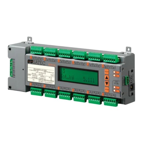
- Page 19 Chapter 2 Installation Controls and Indicators Controls and Indicators Figure 2-14 BFM136 Front View 2.4.1 Indicator LEDs The flashing yellow CPU LED shows that the device is operational and is functioning normally. The green TX and RX LEDs indicate activity on the COM1 communication port. The LEDs flash when the port is receiving or transmitting data.
- Page 20 Chapter 2 Installation Device Settings Device Settings Before operating your BFM136, provide the device with information about your particular environment. The device front display (see Display Operations (BFM136)) and the supplementary PAS software (see Application Software) allow you to configure the BFM136 for your particular use. 2.5.1 Password The BFM136 configuration setups are secured by a factory-preset password.
- Page 21 Chapter 2 Installation Device Settings NOTES Device setup settings, excluding the alarm setpoints and data log setup, are shared across all submeters. Though you can read or write them using any submeter address, your changes affect all submeters in the device. When using the expertpower...
- Page 22 Chapter 2 Installation Device Diagnostics Device Diagnostics Device diagnostic messages may appear as a result of the BFM136 built-in diagnostic tests performed during start-up and device operation. See Device Diagnostic Codes in Appendix F for the list of diagnostic codes and their meanings. The device diagnostics status is stored in a non-volatile register, which may be inspected and cleared via PAS, from the meter display or from a user application.
- Page 23 Chapter 3 BFM136 Graphical Display Operations Startup Diagnostics BFM136 Graphical Display Operations Chapter 3 Startup Diagnostics After applying power to the meter, a start-up diagnostic message is displayed for one second. “Power Up” indicates a normal power-up sequence. You can observe the list of device diagnostic codes recorded during restart and device operation via the Status Display.
- Page 24 Chapter 3 BFM136 Graphical Display Operations Navigation Buttons Navigation Buttons The BFM136 has four push buttons that are normally used to navigate between screen modes and pages. In programming mode, the buttons allow you to navigate through device setup menus and to change the device settings.
- Page 25 Chapter 3 BFM136 Graphical Display Operations Navigation Buttons 3.3.1 Display Views The BFM136 display has 5 multi-page screen modes for viewing numerous measurement parameters shown in the following tables. Scroll through the screen modes by briefly pressing the ENTER button. Scroll through the display pages within the selected mode by briefly pressing the UP and DOWN buttons.
- Page 26 Chapter 3 BFM136 Graphical Display Operations Navigation Buttons Real Time Measurements Page No Page content Description 120.5 V Volts 120.5 V Volts 120.5 V Volts V L12 208.1 V Line to line volts V L23 208.1 V Line to line volts V L31 208.1 V Line to line volts...
- Page 27 Chapter 3 BFM136 Graphical Display Operations Navigation Buttons Summary/TOU Max. Demands Page No Page content Description Reg.2 MD kvar kvar maximum demand Trf.4 0.050 Tariff 4 Reg.2 MD kvar kvar maximum demand Trf.5 0.235 Tariff 5 Reg.2 MD kvar kvar maximum demand Trf.6 0.050 Tariff 6 Reg.2 MD kvar...
- Page 28 Chapter 3 BFM136 Graphical Display Operations Navigation Buttons Total Energy and Maximum Demand Registers Page No Page content Description Total kWh: Total kWh 124100.0 Total kvarh: Total kvarh 124.0 Total kVA: Total kVAh 124100.0 Max.Dmd kW Total kW maximum demand 25.588 Max.Dmd kvar Total kvar maximum demand...
- Page 29 Chapter 3 BFM136 Graphical Display Operations Navigating in Menus Navigating in Menus The BFM136 setup is menu-driven. To enter the setup menus, press the SELECT button for more than 5 seconds. 3.4.1 Entering Numbers Each digit in numbers is adjusted separately with the UP/DOWN buttons. A brief press on the button increments or decrements the highlighted digit by one.
- Page 30 Chapter 3 BFM136 Graphical Display Operations Menu Operations 3.4.4 Viewing and Changing Setup Items COM1 Protocol A second level menu normally consists of three items: the upper-left static item indicates the menu name, while the upper-right item represents a list of setup parameters you can scroll through, and the lower item Modbus RTU shows the present parameter value.
- Page 31 Chapter 3 BFM136 Graphical Display Operations Menu Operations To change the HACS primary rating, highlight desired digits by briefly pressing the SELECT button, then adjust them to the desired value with the UP/DOWN buttons. Press the ENTER button to store your selection. You return to the parameter list to select another SELECT parameter or return to the main menu SubMeter...
- Page 32 Chapter 3 BFM136 Graphical Display Operations Menu Operations 3.5.3 Real Time Clock Setting Jun 06,2005 This menu allows you to adjust internal real time clock. Time 20:47:06 To enter the menu, select the RTC entry from the main menu, and then press the ENTER button. To adjust the clock: SELECT Highlight a time or date item you want to change item by briefly pressing the SELECT button.
- Page 33 Chapter 3 BFM136 Graphical Display Operations Menu Operations 3.5.5 Transformer Correction Transformer correction allows you to compensate ratio and phase angle inaccuracies of the user voltage and current instrument transformers. To enter the menu, select the T.Corr. entry from the main menu, and then press the ENTER button.
- Page 34 Chapter 3 BFM136 Graphical Display Operations Menu Operations 3.5.7 Communication Ports These two menus allow you to configure parameters for communication ports COM1 and COM2. The COM1 Exit BFM136 automatically detects a replaceable communication module and will not allow you to change the baud rate and data format for the Dial-up modem, and for the Ethernet and RF modules.
- Page 35 Chapter 3 BFM136 Graphical Display Operations Menu Operations 3.5.9 Local Settings This menu allows you to configure your local time zone settings. Local Exit To enter the menu, select the Local entry from the main menu, and then press the ENTER button. For instructions on navigating in the menu, see Viewing and Changing Setup Items.
- Page 36 Chapter 3 BFM136 Graphical Display Operations Menu Operations 3.5.11 Display Settings This menu allows you to configure options for the BFM136 display. Display Exit To enter the menu, select the Display entry from the main menu, and then press the ENTER button. For instructions on navigating in the menu, see Viewing and Changing Setup Items.
- Page 37 Chapter 4 PAS Application Software Setting up your Submeters PAS Application Software Chapter 4 The supplemental PAS software can be used for configuring the BFM136 through communication ports, for retrieving real-time and energy profile data, and for remote upgrading device firmware. To run PAS, you need Windows 98, Windows NT, Windows 2000 or Windows XP installed on your computer.
- Page 38 Chapter 4 PAS Application Software Setting up Communications Setting up Communications You can communicate with your meter via a local RS-485 serial port, or remotely through a second adjustable communication port. Depending on what was ordered, your meter may be equipped with an RS-232 or RS-422/485 serial port, with a dial-up modem for communicating through public telephone lines, with an Ethernet module for communicating through the Internet, or with an RF modem for wireless communications.
- Page 39 Chapter 4 PAS Application Software Preparing Setups 4.2.2 Communicating through the Internet If you are communicating via the Ethernet, define the IP address of your BFM136 on the network. On the Instrument Setup tab, select Internet Site. Click on the Connection tab. Click IP address and type in the IP address of your BFM136 .
- Page 40 Chapter 4 PAS Application Software Authorization 4.3.1 Downloading Setups You can update each setup in your BFM136 one at time or download all setups together from the site database. To update a particular setup, check the On-line button on the PAS toolbar, select a submeter site from the list box on the toolbar, and then select the desired setup group from the Meter Setup menu.
- Page 41 Chapter 4 PAS Application Software Changing Port Settings Changing Port Settings This section describes how to configure communication ports in the BFM136 through PAS. The communication settings affect all submeters in your device. 4.5.1 Setting Up Communication Ports To enter the setup dialog, select the site from the list box on the PAS toolbar, select Communications Setup from the Meter Setup menu, and then click on the Serial Ports Setup tab.
- Page 42 Chapter 4 PAS Application Software Changing Port Settings 4.5.3 Configuring Wireless RF Connections To enter the Setup dialog, select the site from the list box on the PAS toolbar, select Communications Setup from the Meter Setup menu, and then click on the RF Modem Setup tab. The following table lists available RF modem options.
- Page 43 The BFM136 has an embedded eXpertPowerTM client that provides communications with the eXpertPowerTM server – the SATEC proprietary Internet services. Connections to the eXpertPowerTM server are handled on a periodic basis. To enter the Setup dialog, select the site from the list box on the PAS toolbar, select Communication Setup from the Meter Setup menu, and then click the ExpertPower Client Setup tab.
- Page 44 Chapter 4 PAS Application Software General Meter Setup General Meter Setup This section describes how to configure the BFM136 for your particular environment and application using PAS. 4.6.1 Basic Meter Setup Before operating your meter, provide the device with basic information about your electrical network. To enter the setup dialog, select the device site from the list box on the PAS toolbar, and then select General Setup from the Meter Setup menu.
- Page 45 Chapter 4 PAS Application Software General Meter Setup Parameter Options Default Description 100000.0 kWh 1000000.0 kWh Energy roll value, kWh 100000000.0 The value at which energy counters roll over to zero 10000000.0 kWh 100000000.0 kWh 5.40 Wh/pulse LED pulse constant - the amount of accumulated Energy LED pulse rate, 0.01-100.00 (one equivalent...
- Page 46 Chapter 4 PAS Application Software General Meter Setup 4.6.2 Channel Assignments The Channel Assignments setup allows you to link the device current terminals to submeters so they can monitor them. Additionally, this setup allows you to specify the primary current rating of the current transformers connected to the device terminals.
- Page 47 4.6.3 Transformer Correction Transformer correction allows you to compensate ratio and phase angle inaccuracies of the user voltage transformers and SATEC current sensors (HACS) instrument. To enter the setup dialog, select the device site from the list box on the PAS toolbar, and then select Transformer Correction from the Meter Setup menu.
- Page 48 Chapter 4 PAS Application Software General Meter Setup 4.6.4 Local Settings The Local Settings setup allows you to specify your time zone and daylight saving time options. To configure the time zone options for your device, select the device site from the list box on the PAS toolbar, select General Setup from the Meter Setup menu, and then click on the Local Settings tab.
- Page 49 Chapter 4 PAS Application Software General Meter Setup 4.6.5 Using Alarm/Control Setpoints BFM136 has an embedded logical controller that runs different actions in response to user-defined internal and external events. Unlike a PLC, the BFM136 uses a simplified programming technique based on setpoints that allows the user to program a required action based on a measured analog value or on a time.
- Page 50 Chapter 4 PAS Application Software Configuring Billing Energy and TOU Registers Delaying Setpoint Operations Two optional delays can be added to each setpoint to extend monitoring a setpoint trigger for a longer time before making a decision on whether the expected event occurred or not. When a delay is specified, the logical controller will change the setpoint status only if all conditions are asserted for a period at least as long as the delay time.
- Page 51 Chapter 4 PAS Application Software Configuring Billing Energy and TOU Registers 4.7.1 Setting up Total and Tariff Registers To configure the device total (summary) and TOU registers, select Energy/TOU from the Meter Setup menu. The available options are shown in the following table: Parameter Options Default...
- Page 52 Chapter 4 PAS Application Software Configuring Billing Energy and TOU Registers Totalization Submeters If you wish to automatically totalize energy measured by a number of submeters by using a separate totalization submeter, select a source submeter in the Source Input column on the Register Source List pane (starting with source 5), and then select the desired target totalization submeter in the Target column.
- Page 53 Chapter 4 PAS Application Software Configuring Billing Energy and TOU Registers 4.7.3 Configuring the Season Tariff Schedule To configure your season tariff schedule, select Energy/TOU from the Meter Setup menu, and then click on the TOU Calendar tab. The TOU calendar allows you to configure any tariff schedule based on any possible utility regulation. The calendar itself has 32 entries that allow you to specify profiles for working days and holidays through all seasons in any order that is convenient for you, based on simple intuitive rules.
- Page 54 Chapter 4 PAS Application Software Configuring Data Recorders Configuring Data Recorders The BFM136 provides a separate Data recorder for each metering submeter. The recorder is triggered via a setpoint periodically for recording interval data (see Using Alarm/Control Setpoints). The device memory is factory partitioned to allow recording one data log file per submeter (Data Log #1) with a maximum of 5000 records per file.
- Page 55 Chapter 4 PAS Application Software Remote Device Control Remote Device Control This section describes some online operations on the BFM136 you can perform through PAS. To access device control options you should have your device online. 4.9.1 Viewing and Clearing Device Diagnostics To view or clear the device diagnostics status, check the On-line button on the PAS toolbar and select Device Control from the Monitor menu.
- Page 56 Chapter 4 PAS Application Software Administration 4.9.3 Clearing Maximum Demands and Log Files PAS allows you to remotely clear maximum demands and log files individually in each submeter. To open the dialog box, select a device site from the list box on the toolbar, check the On-line button, and then select Reset from the Monitor menu.
- Page 57 Chapter 4 PAS Application Software Upgrading Device Firmware 4.11 Upgrading Device Firmware Your meter has upgradeable firmware. If you need to upgrade your device, you can download a new firmware file to the meter through PAS. Firmware can be downloaded through any communication port. The meter can be connected to your PC through a serial interface, a dial-up modem, the Internet, or the RF modem.
- Page 58 Chapter 4 PAS Application Software Data Monitoring Wait until PAS completes upgrading your device. It would take about 3-4 minutes at 115,200 bps to download the file to the device. After upgrading firmware is completed, the device restarts. If the meter is connected to your PC through the modem, communications can be temporarily lost and you may need to wait until PAS restores a connection with your device.
- Page 59 Chapter 4 PAS Application Software Data Monitoring 4.12.2 Retrieving Log Files Using PAS, you can retrieve the event and data log files from the BFM136 submeters and save them to files on your PC in the MS Access database format. Historical data is uploaded on demand any time you need it, or periodically through the Upload Scheduler that retrieves data automatically on a predefined schedule, for example, daily, weekly or monthly.
- Page 60 Chapter 4 PAS Application Software Data Monitoring Branch Feeder Monitor 136_Installation Operation and Manual...
- Page 61 Appendix A Technical Specifications Environmental Conditions Appendix A Technical Specifications Environmental Conditions Indoor use only BFM is intended for operation in environment where normally only non-conductive pollution occurs as defined for pollution degree 2 (UL61010, 3.6.6.2) Operating Temperature: -40°C to 70°C (-40°F to 158°F) Storage Temperature: -40°C to 80°C (-40°F to 176°F) Humidity: 0 to 95% non-condensing Altitude: 2,000m max...
- Page 62 Appendix A Technical Specifications Communication Ports Communication Ports COM2 (Optional modules) Serial EIA RS-232 optically isolated port Connector Type: DB9 female. Baud Rate: up to 115.2 kbps. Supported Protocols: Modbus RTU/ASCII. RS-422/RS-485 optically isolated port Connector Type: removable, captured-wire, 5 terminals. Wire Size: up to 12 AWG (up to 2.5 mm2).
- Page 63 Appendix A Technical Specifications Measurement Specifications Measurement Specifications Accuracy Full Scale @ Input Parameter Range Range Conditions Reading = 120V, Voltage 0.05 90 to 315 V 0 to Vmax= 600 V = 230V 0 to HACS primary Instrument current Line current current transformer CTs 0.05 1 to 100% FS...
- Page 64 Appendix B HACS Connection Template Appendix B HACS Connection Template Use the following table to memorize your input assignments and wiring connections for sub-consumers. Sub-consumer Input # Wire Color Cable# Phase #1 through #36 Branch Feeder Monitor 136_Installation Operation and Manual...
- Page 65 Appendix C Parameters for Data Monitoring and Logging Appendix C Parameters for Data Monitoring and Logging The following table lists parameters measured by the meter that are available for data logging and monitoring through communications. The left column shows data abbreviations used in PAS. Parameter groups are highlighted in bold.
- Page 66 Appendix C Parameters for Data Monitoring and Logging Designation Description V3 Voltage I1 Current I2 Current I3 Current kW L1 kW L1 kW L2 kW L2 kW L3 kW L3 kvar L1 kvar L1 kvar L2 kvar L2 kvar L3 kvar L3 kVA L1 kVA L1...
- Page 67 Appendix C Parameters for Data Monitoring and Logging Designation Description kvar IMP ACC DMD kvar import accumulated demand kvar EXP ACC DMD kvar export accumulated demand kVA ACC DMD kVA accumulated demand kW IMP PRD DMD kW import predicted sliding window demand kW EXP PRD DMD kW export predicted sliding window demand kvar IMP PRD DMD...
- Page 68 Appendix C Parameters for Data Monitoring and Logging Designation Description TOU Energy Register #1 1 TOU REG1 TOU REG1 TRF1 Tariff #1 register TOU REG1 TRF2 Tariff #2 register TOU REG1 TRF3 Tariff #3 register TOU REG1 TRF4 Tariff #4 register TOU REG1 TRF5 Tariff #5 register TOU REG1 TRF6...
- Page 69 Appendix C Parameters for Data Monitoring and Logging Designation Description DMD3 TRF4 MAX Tariff #4 register DMD3 TRF5 MAX Tariff #5 register DMD3 TRF6 MAX Tariff #6 register TOU Maximum Demand Register #4 1 TOU MAX DMD REG4 DMD4 TRF1 MAX Tariff #1 register DMD4 TRF2 MAX Tariff #2 register...
- Page 70 Appendix D Setpoints Triggers and Actions Appendix D Setpoints Triggers and Actions D.1.1 Setpoint Triggers Designation Description NONE None (condition is not active) MINUTE INTERVAL Minute intervals (10, 15, 30, 60 min) synchronized with the clock HIGH V1 High V1 voltage HIGH V2 High V2 voltage HIGH V3...
- Page 71 Appendix E Data Scales Appendix E Data Scales The maximum values for volts, amps and power in the BFM136 setup and in communications are limited by the voltage and current scale settings. See Basic Meter Setup in Chapter 4 on how to change the voltage scale in your meter.
- Page 72 Appendix F Device Diagnostic Codes Appendix F Device Diagnostic Codes Diagnostic Startup Display Description Reason Code Message RAM/Data Error Memory/Data error Hardware failure WDT Reset Hardware watchdog reset Hardware failure Sampling Fault Sampling fault Hardware failure CPU Exception CPU exception Hardware failure Run-Time Error Run-time software error...
Need help?
Do you have a question about the BFM 136 and is the answer not in the manual?
Questions and answers