Table of Contents
Advertisement
Quick Links
Advertisement
Table of Contents
Troubleshooting

Related Manuals for Ruijie RG-S6220-48XS6QXS-H


Summary of Contents for Ruijie RG-S6220-48XS6QXS-H
- Page 1 RG-S6220-H Series Switches Hardware Installation and Reference Guide V1.08...
- Page 2 This document is provided “as is”. The contents of this document are subject to change without any notice. Please obtain the latest information through the Ruijie Networks website. Ruijie Networks endeavors to ensure content accuracy and will not shoulder any responsibility for losses and damages caused due to content omissions, inaccuracies or errors.
- Page 3 Appendix D “Cabling Recommendations in Installation” Appendix E “Site Selection” Appendix F “Mini USB Console Driver Installation” Obtaining Technical Assistance Ruijie Networks website: http://www.ruijienetworks.com/ Service Email: service_rj@ruijienetworks.com Technical Support: http://www.ruijienetworks.com/service.aspx Technical Support Hotline: +86-4008-111-000...
- Page 4 Describes the related configuration commands, including command modes, Command Reference parameter descriptions, usage guides, and related examples. Symbol Conventions Means reader take note. Notes contain helpful suggestions or references. Means reader be careful. In this situation, you might do something that could result in equipment damage or loss of data.
-
Page 5: Product Overview
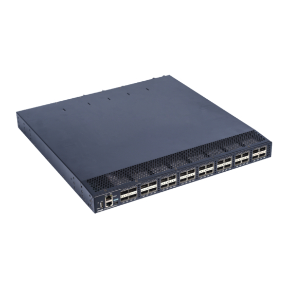
Product Overview 1 Product Overview Ruijie S6220-H series switches are the data center-oriented high-density 10G layer 3 IPv6 box switches. They are mainly applicable to the data center to provide the convergence access for the servers. The RG-S6220-H Series Switches:... - Page 6 The 10G or 40G Ethernet port of the RG-S6220-48XS6QXS-H switch supports DAC. The SFP+ port supports 1-meter, 3-meter and 5-meter cable, and the QSFP+ port supports 3-meter cable. For a detailed model and specification, refer to Appendix B.
- Page 7 QSFP+ port status indicator SFP+ port status indicator QSFP+ port The RG-S6220-48XS6QXS-H supports 10G SFP+ module and 1G SFP module. But the 10G SFP+ module cannot function as the 1G SFP module. Back Panel Figure 1-3 Back Panel of the RG-S6220-48XS6QXS-H...
- Page 8 Users can mark the information such as asset name, category, code and registration date on the label which helps to improve asset management accuracy and efficiency. Figure 1-4 Asset Management Label of the RG-S6220-48XS6QXS-H External Ports The RG-S6220-48XS6QXS-H provides the following ports: ...
- Page 9 Hardware Installation and Reference Guide Product Overview Panel Indicator Status Meaning Identification The system is not powered up. One of the modules of the system fails. There are less than 2 fans. Solid red The internal or partial temperature exceeds the warning working temperature, and the switching Switch status indicator service resets.
- Page 10 Hardware Installation and Reference Guide Product Overview The working temperature of the RG-S6220-48XS6QXS-H switches is 0ºC to 50ºC, or 32ºF to 122ºF, and the heat dissipation design needs to ensure the stability, safety and maintainability in such environment. The RG-S6220-H series switches adopt fan ventilation and forced convection to ensure the device can work normally in specified environment.
- Page 11 Frequency: 50 Hz to 60 Hz Rated current range: 5.29A to 2.2A Power Less than 424 W Consumption Refer to Appendix B Optical Module The supported modules update at any time, contact Ruijie Networks for details. SFP+ Port Unsupported QSFP+ Port Supported FC Port Unsupported...
- Page 12 Hardware Installation and Reference Guide Product Overview The heat dissipation system: Provides three fan module slots, which support 2+1 fan redundancy. It is recommended users configure all fans redundancy. Figure 1-7 Appearance of the RG-S6220-48XT6QXS-H Front Panel Figure 1-8 Front Panel of the RG-S6220-48XT6QXS-H Notes: Switch status indicator 10GBASE-T port...
- Page 13 Hardware Installation and Reference Guide Product Overview Notes: Power supply module slot USB 2.0 port Fan module slot Console port MGMT port MiniUSB port MGMT port status indicator 10. Switch status indicator Switch locator status indicator 11. Asset management label Grounding connector Asset Management Label The asset management label is next to the switch status indicator of the switch back panel.
- Page 14 Hardware Installation and Reference Guide Product Overview 10GBASE-T port: There are 48 10GBASE-T ports, which are downward compatible with 1000BASE-T and 100BASE-TX. QSFP+ port: There are six 40G QSFP+ ports, which support optical modules and DAC. This port can work in 4x10G mode.
- Page 15 Hardware Installation and Reference Guide Product Overview The RG-S6220-H series switches support 1+1 power supply redundancy. To improve the stability and reliability of the entire system, it is recommended to configure 1+1 power supply redundancy. When the two power supply modules work normally, the switch is in the status of current sharing.
- Page 16 Frequency: 50 Hz to 60 Hz Rated current range: 5.29A to 2.2A Power Less than 250 W Consumption Refer to Appendix B Optical Module The supported modules update at any time, contact Ruijie Networks for details. SFP+ Port Unsupported Supported QSFP+ Port FC Port Unsupported...
- Page 17 Hardware Installation and Reference Guide Product Overview Figure 1-12 Appearance of the RG-S6220-32QXS-H Front Panel Figure 1-13 Front Panel of the RG-S6220-32QXS-H Notes: Locator status indicator Switch status indicator Link indicator of the MGMT port USB 2.0 port MGMT port Console port Act indicator of the MGMT port MiniUSB port...
- Page 18 Hardware Installation and Reference Guide Product Overview Notes: Power supply module slot Asset management label Fan module slot Grounding connector Asset Management Label The asset management label is in the lower right corner of the switch back panel. The label is movable and can be withdrawn from the device.
- Page 19 Hardware Installation and Reference Guide Product Overview Panel Indicator Status Meaning Identification The system is not powered up. One of the modules of the system fails. There are less than 2 fans. Solid red The internal temperature exceeds the warning working temperature, and the switching service resets.
- Page 20 Hardware Installation and Reference Guide Product Overview series switches adopt fan ventilation and forced convection to ensure the device can work normally in specified environment. Dust the device every three months to avoid blocking the ventilation openings. The RG-S6220-48XT6QXS-H supports fan module M6220-FAN-F and provides fan speed regulation, fan failure warning, and fan hot swapping.
- Page 21 Hardware Installation and Reference Guide Product Overview Notes: Status indicator Indicator Panel Indicator Status Meaning Identification The fan is not powered up. Status Indicator Status Solid green The fan is operational. Solid red The fan fails or stops. Specifications Fan Model M6220-FAN-F Ventilation 30 CFM...
- Page 22 Hardware Installation and Reference Guide Product Overview Notes: Status indicator Indicator Panel Indicator Status Meaning Identification The fan is not powered up. Status Indicator Status Solid green The fan is operational. Solid red The fan fails or stops. Specifications M6220-FAN II-F Fan Model Ventilation 20 CFM...
- Page 23 Hardware Installation and Reference Guide Product Overview Indicator Panel Indicator Status Meaning Identification No power input or the power supply fails. Status Indicator Solid green The power input is normal. Specifications Module Model M6220-AC460E-F (AC input) M6220-AC460E-F (HVDC input) Rated Voltage 100 VAC to 240 VAC;...
- Page 24 166 mm x 55.7 mm x 41.2 mm (L x W x H) 1.4.5 M6220-AC460E-R The M6220-AC460E-R is the power supply module of the RG-S6220-48XS6QXS-H series and provides power supply for the RG-S6220-48XS6QXS-H series. The smart power supply module M6220-AC460E-R can access information such as the power supply status, output power and current, and working temperature at any time.
-
Page 25: Preparation Before Installation
Hardware Installation and Reference Guide Preparation before Installation Dimensions 243.2 mm x 86.4 mm x 39.9 mm (L x W x H) Power Cord 10 A power cord Requirement Make sure the power cord is removed before plugging or unplugging the power supply. 1.4.6 M6220-DC460E-F The M6220-DC460E-F is the power supply module of the RG-S6220 series and provides power supply for the RG-S6220 series. -
Page 26: Installation Safety
Hardware Installation and Reference Guide Preparation before Installation 2.1.1 Installation Safety Keep the chassis clean and dust-free. Do not place the device in walking areas. Do not wear loose clothes, ornaments or any other things that may be hooked by the chassis during the installation and maintenance. -
Page 27: Laser Safety
Hardware Installation and Reference Guide Preparation before Installation Pay attention to the following tips: The device and the floor are well grounded. Take dust prevention measures in the room. Maintain an appropriate humidity. When the pluggable modules of the switch are being installed, wear antistatic wrist strap and make sure the antistatic wrist strap is well grounded. -
Page 28: Temperature And Humidity Requirements
Temperature and humidity requirements of the RG-S6220-H: Model Working Temperature Working Humidity RG-S6220-48XS6QXS-H 0º C to 50º C / 32º F to 122º F 10% to 95% RG-S6220-48XT6QXS-H 0º C to 45º C / 32º F to 113º F... -
Page 29: System Grounding Requirements
Hardware Installation and Reference Guide Preparation before Installation Average (mg/m Maximum (mg/m The Average refers to the average limit of harmful gas in one week. The Maximum value is the upper limit of the harmful gas in one week, and maximum value can last for up to 30 minutes every day. 2.2.5 System Grounding Requirements A good grounding system is the basis for the stable and reliable operation of the RG-S6220-H. -
Page 30: Precaution For Fiber Connection
Hardware Installation and Reference Guide Preparation before Installation electromagnetic interferences: radiated interference and conducted interference, depending on the type of the propagation path. When the energy, often RF energy, from a component arrives at a sensitive component via the space, the energy is known as radiated interference. -
Page 31: Product Installation
Hardware Installation and Reference Guide Product Installation 3 Product Installation RG-S6220-H series Ethernet switch must be used and fixed in the room. Make sure you have carefully read part 2, and be sure that the requirements set forth in part 2 have been met. 3.1 Installation Procedure Assemble RG-S6220-H before installation... -
Page 32: Cabinet Installation
Hardware Installation and Reference Guide Product Installation The related network cables have already been deployed at the installation location. 3.3 Cabinet Installation Precautions When you install the cabinet, pay attention to the following requirements: All expansion bolts for fastening the cabinet base to the ground should be installed and tightened in sequence from bottom up (large plain washer, spring washer, and nut), and the installation holes on the base and the expansion bolts should be well aligned. - Page 33 Hardware Installation and Reference Guide Product Installation should reserve space of at least 10mm between the front panel of the equipment and that of the cabinet after installation. Before mounting into a cabinet, you need to make sure the following conditions are met: ...
- Page 34 Hardware Installation and Reference Guide Product Installation The mounting brackets are located at the four of the six screw holes at both sides on the back panel of the host. Distinguish the left and the right rear brackets according to the marked directions. The rear brackets provided are only applicable for cabinets with depth of 800mm - 1200mm.
-
Page 35: Installing And Removing A Fan Module
Hardware Installation and Reference Guide Product Installation 3.5 Installing and Removing a Fan Module Wear anti-static gloves before the following operations. Installing an M6220-FAN-F/M6220-FAN II-F/M6220-FAN II-R Fan Module Take out a new fan module from the fan module box. Hold the handle at the end of the fan module. Insert the fan module to the chassis slowly along the guide rail until it is fully seated, and make sure that it is in good contact with the slot. - Page 36 Hardware Installation and Reference Guide Product Installation 3.6 Installing and Removing a Power Module Wear anti-static gloves before the following operations. Installing an RG-M6220-AC460E-F/RG-M6220-AC460E-R Power Module Take a new power module out of the package and confirm the input mode and the input parameters of the power module match the requirements.
- Page 37 Hardware Installation and Reference Guide Product Installation Remove the power module uprightly and slowly. Install a filler panel in the location where the power module is removed to ensure the normal ventilation and dissipation and avoid the dust in the chassis. 3.7 Grounding A PGND is installed on the back of RG-S6220-H.
-
Page 38: Connecting The External Interface Cables
Hardware Installation and Reference Guide Product Installation Connect the RJ45 connector to the Console interface of the management engine module with shipped console cable , and connect the DB9 connector to the NM or control terminal. By default, the baud rate is 9600, data bit 8, parity check none, stop bit 1, and flow control none. 3.9 Connecting the External Interface Cables Precautions ... - Page 39 Hardware Installation and Reference Guide Product Installation After equipment is installed, verify if the front/back cabinet doors can be closed. Verify that the cabinet has been fastened completely, and does not move or tilt. Verify that the equipment has been installed in the cabinet, and all the cables have been fastened to the cabinet. ...
-
Page 40: System Debugging
Hardware Installation and Reference Guide System Debugging 4 System Debugging 4.1 Establishing the Configuration Environment Establishing the Configuration Environment Connect the PC to the console port of the switch through the console cable, as shown in Figure 4-1. Figure 4-1 Schematic diagram of the configuration environment Connecting the Console Cable Connect one end of the DB-9 jack of the console cable to the serial port of the PC. - Page 41 Hardware Installation and Reference Guide System Debugging Figure 4-2 Enter the name of the new connection and click OK. A window appears as shown in Figure 4-3. In the column of Connect Using field, select the serial port you want to use. Figure 4-3 After the serial port is selected, please click OK.
-
Page 42: Power-On Startup
Hardware Installation and Reference Guide System Debugging After the serial port parameters are set, click OK to enter hyper terminal window. 4.2 Power-on Startup Checking before Power-on Check if the switch is fully grounded. Check if the fan module and the power module are correctly installed. ... -
Page 43: Monitoring And Maintenance
Hardware Installation and Reference Guide Monitoring and Maintenance 5 Monitoring and Maintenance 5.1 Monitoring Indicator When the RG-S6220-H is running, users can monitor the status of host and each module by inspecting corresponding indicators. When the Status indicator is red, it means the system has a fault, in which case you can determine and eliminate the fault by viewing with the management software. - Page 44 The built-in lithium batteries can support the real time clock of the RG-S6220-H series switches without external power supply. Please contact the technical support representatives of Ruijie Networks for replacing lithium batteries. Technical staff of Ruijie Networks will replace the battery of the same model.
-
Page 45: Troubleshooting
Check the installation and fastening of the modules Check the indicators on the device and the modules Check the connection of the serial ports and its parameters Check the connection of the fibers or cables of various ports Contact Technical Support of Ruijie Networks for hardware problems... -
Page 46: Common Troubleshooting Procedures
RG-S6220-H Software Configuration Guide. If not, modify the serial port configuration parameters. If there is still no serial port printed information, please contact Ruijie Customer Service Department for technical support. - Page 47 Check whether the module is inserted correctly. If the newly-inserted module still cannot be powered on even though the checking is ok, please contact Ruijie Customer Service Department for technical support. Fault 7: The link cannot be set up between fiber interfaces [Fault Description] The system runs normally.
-
Page 48: Appendix A Connectors And Connection Media
Hardware Installation and Reference Guide Appendix A Connectors and Connection Media Appendix A Connectors and Connection Media 10GBASE-T/1000BASE-T/100BASE-TX Port 10GBASE-T/1000BASE-T/100BASE-TX is a port that supports self-adaptation of three rates, and automatic MDI/MDIX Crossover at these three rates. 10GBASE-T complies with IEEE 802.3an standard, and the supported cables and cabling distances are listed in the following table. - Page 49 Hardware Installation and Reference Guide Appendix A Connectors and Connection Media Figure A-1 Four twisted pairs of the 1000BASE-T In addition to the above cables, the 100BASE-TX can use up to 100m of 100-ohm CAT5. Figure A-2 shows the definition of pin signal concerning the 100BASE-TX: Figure A-2 Definition of pin signal concerning the 100BASE-TX Socket Plug...
-
Page 50: Appendix B Mini-Gbic, 10G And 40G Module
Hardware Installation and Reference Guide Appendix B Mini-GBIC, 10G and 40G Module Appendix B Mini-GBIC, 10G and 40G Module We provide 1000M SFP modules (Mini-GBIC modules), 10G SFP+ modules and 40G QSFP+ modules. According to the interface type of the switch module. You can select modules to suit your specific needs. The following models and technical specifications of some 1000M SFP modules, 10G SFP+ modules and 40G QSFP+ modules are listed for your reference. - Page 51 Hardware Installation and Reference Guide Appendix B Mini-GBIC, 10G and 40G Module The existing 10G SFP+ optical modules: Intensity of Intensity of Optical Core Modular Transmitted Received Wavelength Model Fiber Size Bandwidth Cabling (nm) Light (dbm) Light (dbm) (μm) Type (MHz·km) distance 62.5...
- Page 52 Hardware Installation and Reference Guide Appendix B Mini-GBIC, 10G and 40G Module -13.7 to 40G-QSFP-LR -7.0 to 2.3 1310 10km 4-SM1310 (Perlane) (Perlane) The existing 40G QSFP+ copper modules: Copper Conductor Support Module Connector Model Cable Wire Diameter Data Rate(Gb/s) Type Type Length (m)
-
Page 53: Appendix C Lightning Protection
Hardware Installation and Reference Guide Appendix C Lightning Protection Appendix C Lightning Protection Installing AC Power Arrester (lightning protection cable row) The external lightning protection cable row should be used on the AC power port to prevent the switch from being struck by lightning when the AC power cable is introduced from the outdoor and directly connected to the power port of the switch. - Page 54 Hardware Installation and Reference Guide Appendix C Lightning Protection Installing the Ethernet Port Arrester During the switch usage, the Ethernet port arrester should be connected to the switch to prevent the switch damage by lightning before the outdoor network cable connects to the switch . Tools: Cross or straight screwdriver, Multimeter, Diagonal pliers Installation Steps: Tear one side of the protection paper for the double-sided adhesive tape and paste the tape to the framework of the...
- Page 55 Hardware Installation and Reference Guide Appendix C Lightning Protection You should pay attention to the following conditions during the actual installation to avoid influencing the performance of the Ethernet port arrester: Reversed direction of the arrester installation. You shall connect the external network cable to the “IN” end and connect the switch Ethernet port to the “OUT”...
-
Page 56: Appendix D Cabling Recommendations In Installation
Hardware Installation and Reference Guide Appendix D Cabling Recommendations in Installation Appendix D Cabling Recommendations in Installation When the switches are installed in standard 19-inch cabinets, the cables are tied in the binding rack on the cabinet by the cable management bracket, and top cabling or bottom cabling is adopted according to the actual situation in the equipment room. - Page 57 Hardware Installation and Reference Guide Appendix D Cabling Recommendations in Installation Cables of different types (such as power cords, signal cables, and grounding cables) should be separated in cabling and bundling and no mixed bundling is allowed. When they are close, crossover cabling can be adopted. In the case of parallel cabling, power cords and signal cables should maintain a distance not less than 30 mm.
- Page 58 Hardware Installation and Reference Guide Appendix D Cabling Recommendations in Installation Cables not to be assembled or remaining parts of cables should be folded and placed in a proper position of the cabinet or cabling slot. The proper position indicates a position that will not affect device running or cause device damage or cable damage during commissioning.
- Page 59 Hardware Installation and Reference Guide Appendix D Cabling Recommendations in Installation Figure D-4 Cable fastening The hard power cable should be fastened at the terminal connection area to prevent stress on terminal connection and cable. Do not use self-tapping screws to fasten terminals. ...
-
Page 60: Appendix E Site Selection
Hardware Installation and Reference Guide Appendix E Site Selection Appendix E Site Selection The machine room should be at least 5km away from the heavy pollution source such as the smelter, coal mine and thermal power plant, 3.7km away from the medium pollution source such as the chemical industry, rubber industry and electroplating industry, and 2km away from the light pollution source such as the food manufacturer and leather plant. -
Page 61: Appendix F Mini Usb Console Driver Installation
Hardware Installation and Reference Guide Appendix F Mini USB Console Driver Installation Appendix F Mini USB Console Driver Installation The Mini USB Console driver can be downloaded on the official TI website (http://www.ti.com/). The driver is now supported only on 32-bit Windows XP, 64-bit Windows XP, 32-bit Window Vista, 64-bit Window Vista, 32-bit Windows 7, and 64-bit Windows 7. - Page 62 Hardware Installation and Reference Guide Appendix F Mini USB Console Driver Installation Step 3: Select the unpackage directory and click Install. Step 4: After the driver is installed, click Finish.
- Page 63 Hardware Installation and Reference Guide Appendix F Mini USB Console Driver Installation After the Mini USB Console driver is installed, you are able to perform commissioning on devices with Mini USB ports using Type-A male USB to male Mini USB cables. Right click Computer, choose Manage-Device Manager-Ports (COM &...
Need help?
Do you have a question about the RG-S6220-48XS6QXS-H and is the answer not in the manual?
Questions and answers