Table of Contents
Advertisement
Quick Links
FEATURES
Board supports
ADPD7000
►
6 separately driven LEDs are included: 3 green LEDs around the
►
center and 3 packaged LEDs, each of which includes 1 infrared
LED and 1 red LED
4 channels of photodiode input: two channels with a single PD
►
and two channels with a double PD
Works with the VSM Client evaluation software allowing the
►
following:
Time domain graphing and logging
►
Selection of supported functions, including PPG, BIA, EDA,
►
and ECG
Real-time data display with various combinations of the sup-
►
ported functions
EVALUATION KIT CONTENTS
EVAL-ADPD7000Z evaluation board
►
EVAL-VSMUCZ
microcontroller board
►
Soft cable to connect the EVAL-ADPD7000Z and EVAL-
►
VSMUCZ
ADDITIONAL EQUIPMENT NEEDED
USB to Type-C cable
►
3.7 V battery
►
ONLINE RESOURCES
ADPD7000 data sheet
►
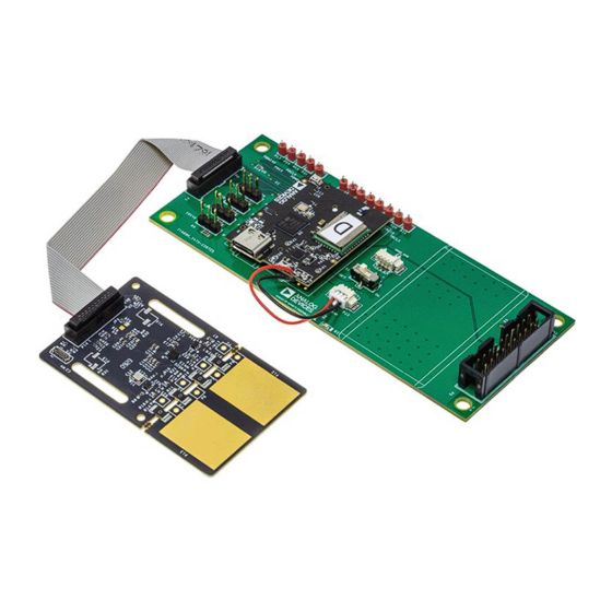
EVALUATION BOARD PHOTOGRAPH
PLEASE SEE THE LAST PAGE FOR AN IMPORTANT
WARNING AND LEGAL TERMS AND CONDITIONS.
Evaluating the ADPD7000 Multimodal Sensor Front End
population
Figure 1. EVAL-ADPD7000Z Evaluation Board Photograph
User Guide | EVAL-ADPD7000
VSM Client software (available on the EVAL-ADPD7000 product
►
page)
GENERAL DESCRIPTION
This user guide describes the operation of the EVAL-ADPD7000Z
demonstration kit, which is an evaluation module for the
ADPD7000.
The ADPD7000 is a fully Integrated analog front end (AFE) for
wearable vital signal monitoring (VSM) devices. The key functions
of the ADPD7000 include photoplethysmography (PPG), electrocar-
diogram (ECG), body impedance analysis (BIA), and electrodermal
activity (EDA).
This demonstration kit includes both software and hardware. The
EVAL-ADPD7000Z can evaluate the AFE feature and verify the
system design based on the AFE. According to the requirements of
the application, the user can use a cable connection or Bluetooth
connection to establish communication between the PC and the
EVAL-ADPD7000Z demonstration kit.
This document also describes an example configuration of the
different functions of the ADPD7000.
For full details on the ADPD7000, see the ADPD7000 data sheet,
which must be consulted in conjunction with this user guide when
using the EVAL-ADPD7000Z.
UG-2108
Rev. 0 | 1 of 24
Advertisement
Table of Contents

Related Manuals for Analog Devices EVAL-ADPD7000


Summary of Contents for Analog Devices EVAL-ADPD7000
-
Page 1: Features
User Guide | EVAL-ADPD7000 UG-2108 Evaluating the ADPD7000 Multimodal Sensor Front End VSM Client software (available on the EVAL-ADPD7000 product FEATURES ► page) Board supports ADPD7000 population ► GENERAL DESCRIPTION 6 separately driven LEDs are included: 3 green LEDs around the ►... -
Page 2: Table Of Contents
User Guide EVAL-ADPD7000 TABLE OF CONTENTS Features..............1 Power on the Bluetooth Connection....5 Evaluation Kit Contents......... 1 Add Device via Bluetooth........5 Additional Equipment Needed....... 1 VSM Client.............7 Online Resources..........1 Find the Device on the VSM Client....7 General Description..........1 Configure the Device..........8... -
Page 3: Preparation And Setup
User Guide EVAL-ADPD7000 PREPARATION AND SETUP EVAL-ADPD7000Z COMPONENTS Figure 2 shows the components needed for evaluation. Figure 4. EVAL-VSMUCZ Connection Figure 2. EVAL-ADPD7000Z Demonstration Kit Components PCB CONNECTION Take the following steps to connect the printed circuit board (PCB). 1. Connect the battery to the connector on the EVAL-VSMUCZ board. -
Page 4: Software Installation
User Guide EVAL-ADPD7000 SOFTWARE INSTALLATION The VSM Client software is the graphical user interface (GUI) used for the EVAL-ADPD7000Z demonstration kit. The VSM Client software is available on the EVAL-ADPD7000Z product page. Take the following steps to install the VSM Client software: 1. -
Page 5: Power On The System
User Guide EVAL-ADPD7000 POWER ON THE SYSTEM After preparing the hardware and installing the software, the EVAL- ADPD7000Z is ready to power on. POWER ON THE CABLE CONNECTION Connect the USB to the Type-C cable from the PC to J5 on the EVAL-VSMUCZ to power on the EVAL-ADPD7000Z automatically. - Page 6 User Guide EVAL-ADPD7000 POWER ON THE SYSTEM 4. Select the EVAL-VSMUCZ from the list of devices (in this example, Figure 14 shows the device as B8-7425A2). The device is now connected (see Figure 15). Figure 14. Select EVAL-VSMUCZ Figure 15. Device Connected After adding the EVAL-VSMUCZ, two Bluetooth serial ports appear in the Device Manager window.
-
Page 7: Vsm Client
User Guide EVAL-ADPD7000 VSM CLIENT 4. Toggle the connection switch to Connect (see Figure 20). FIND THE DEVICE ON THE VSM CLIENT When connected, a Success to connect target! pop-up ap- Take the following steps to find the device on the VSM Client... -
Page 8: Configure The Device
User Guide EVAL-ADPD7000 VSM CLIENT Figure 27. Configuration File Folder 3. Click Load (see Figure 28) to load the configuration file. Figure 24. Select Function CONFIGURE THE DEVICE Take the following steps to configure the device: 1. Click Load cfg File in the configuration interface of the VSM... -
Page 9: Receive The Data
If the export is successful, a Success to export data pop-up appears (see Figure 39) noting the location of the .xlsx file as follows: C:\Analog Devices\VSM Client\VSM_Client\Export. In the Export folder, the file name notes the date, time, and corresponding function of the export (see Figure 40). - Page 10 User Guide EVAL-ADPD7000 VSM CLIENT Figure 42. Clear Plot Data Figure 38. Stop Export 8. On the EVAL-ADPD7000Z, place a white reflective card before LED and PD pair to get a DC waveform (see Figure 43) that can be used to measure the performance of the system such as signal-to-noise ratio (SNR), noise, and ambient light rejection (ALR).
-
Page 11: Human Measurement
User Guide EVAL-ADPD7000 HUMAN MEASUREMENT Measurement, Measurement, Measurement, EDA Measurement sections provide a brief guide on using the EVAL-ADPD7000Z for human measurement. The example wave- forms in these sections are for reference only and do not illustrate the performance of the system. The detailed characteristics relate to the configuration and measurement environment. -
Page 12: Bia Measurement
User Guide EVAL-ADPD7000 HUMAN MEASUREMENT Table 2. BIA Connection Relationship (Continued) BIAx ELECx Electrode Board Pin Connection Connection Connect to BIA3 ELEC3 IMPIN BIA4 ELEC4 EXCN For BIA measurement, place the electrode board against the wrist in the same way as shown for ECG measurement (see... - Page 13 User Guide EVAL-ADPD7000 HUMAN MEASUREMENT Figure 53. Example EDA Waveform analog.com Rev. 0 | 13 of 24...
-
Page 14: Evaluation Board Schematics And Artwork
User Guide EVAL-ADPD7000 EVALUATION BOARD SCHEMATICS AND ARTWORK Figure 54. EVAL-ADPD7000Z Schematic, Page 1 analog.com Rev. 0 | 14 of 24... - Page 15 User Guide EVAL-ADPD7000 EVALUATION BOARD SCHEMATICS AND ARTWORK Figure 55. EVAL-ADPD7000Z Schematic, Page 2 analog.com Rev. 0 | 15 of 24...
- Page 16 User Guide EVAL-ADPD7000 EVALUATION BOARD SCHEMATICS AND ARTWORK Figure 56. EVAL-ADPD7000Z PCB Layout: Top analog.com Rev. 0 | 16 of 24...
- Page 17 User Guide EVAL-ADPD7000 EVALUATION BOARD SCHEMATICS AND ARTWORK Figure 57. EVAL-ADPD7000Z PCB Layout: GND 1 analog.com Rev. 0 | 17 of 24...
- Page 18 User Guide EVAL-ADPD7000 EVALUATION BOARD SCHEMATICS AND ARTWORK Figure 58. EVAL-ADPD7000Z PCB Layout: Inner Signal analog.com Rev. 0 | 18 of 24...
- Page 19 User Guide EVAL-ADPD7000 EVALUATION BOARD SCHEMATICS AND ARTWORK Figure 59. EVAL-ADPD7000Z PCB Layout: Power analog.com Rev. 0 | 19 of 24...
- Page 20 User Guide EVAL-ADPD7000 EVALUATION BOARD SCHEMATICS AND ARTWORK Figure 60. EVAL-ADPD7000Z PCB Layout: GND 2 analog.com Rev. 0 | 20 of 24...
- Page 21 User Guide EVAL-ADPD7000 EVALUATION BOARD SCHEMATICS AND ARTWORK Figure 61. EVAL-ADPD7000Z PCB Layout: Bottom analog.com Rev. 0 | 21 of 24...
- Page 22 User Guide EVAL-ADPD7000 EVALUATION BOARD SCHEMATICS AND ARTWORK Figure 62. EVAL-ADPD7000Z PCB Layout: Assembly Top analog.com Rev. 0 | 22 of 24...
- Page 23 User Guide EVAL-ADPD7000 EVALUATION BOARD SCHEMATICS AND ARTWORK Figure 63. EVAL-ADPD7000Z PCB Layout: Assembly Bottom analog.com Rev. 0 | 23 of 24...
- Page 24 Evaluation Board until you have read and agreed to the Agreement. Your use of the Evaluation Board shall signify your acceptance of the Agreement. This Agreement is made by and between you (“Customer”) and Analog Devices, Inc. (“ADI”), with its principal place of business at Subject to the terms and conditions of the Agreement, ADI hereby grants to Customer a free, limited, personal, temporary, non-exclusive, non-sublicensable, non-transferable license to use the Evaluation Board FOR EVALUATION PURPOSES ONLY.
Need help?
Do you have a question about the EVAL-ADPD7000 and is the answer not in the manual?
Questions and answers