Table of Contents
Advertisement
Quick Links
One Technology Way • P.O. Box 9106 • Norwood, MA 02062-9106, U.S.A. • Tel: 781.329.4700 • Fax: 781.461.3113 • www.analog.com
FEATURES
ADPD2140
full configuration
Register level
Parameter level
Graph views
Time series view
Gesture recognition view
Triangulation view
UDP transfer capability
EVALUATION KIT CONTENTS
EVAL-ADPD2140Z standard evaluation board
USB-C cable
ADDITIONAL EQUIPMENT NEEDED
EVAL-ADPDM3Z
evaluation board
PC running Windows® 7 operating system
ONLINE RESOURCES
ADPD2140
data sheet
Applications Wavetool
PLEASE SEE THE LAST PAGE FOR AN IMPORTANT
WARNING AND LEGAL TERMS AND CONDITIONS.
Evaluating the
ADPD2140
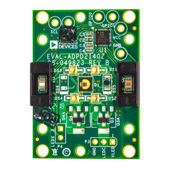
EVALUATION BOARD PHOTOGRAPH
EVAL-ADPD2140Z
IR Light Angle Sensor
GENERAL DESCRIPTION
The EVAL-ADPD2140Z evaluation kit allows users to interface
with the
ADPD2140
from the ADPD2140, and evaluate gesture recognition and
triangulation capabilities.
The evaluation kit requires the
board and the
Applications
(GUI) that provides users with low level and high level config-
urability, real-time data analysis, and user datagram protocol
(UDP) transfer capability, which allows the
evaluation board to interface to a PC. The
Wavetool
can be downloaded from the EVAL-ADPD2140Z
evaluation board product page.
The USB port of the PC powers the
evaluation board and provides power to the EVAL-ADPD2140Z
evaluation board. On-board voltage regulators provide voltage
supplies for the ADPD2140.
The EVAL-ADPD2140Z evaluation board schematic indicates
signal names for easy identification (see Figure 12).
Full specifications for the
ADPD2140
data sheet, which should be consulted in conjunction
with this user guide when working with the EVAL-ADPD2140Z
evaluation board.
Figure 1.
Rev. 0 | Page 1 of 7
User Guide
infrared (IR) light angle sensor, collect data
EVAL-ADPDM3Z
Wavetool, a graphical user interface
EVAL-ADPDM3Z
Applications
EVAL-ADPDM3Z
ADPD2140
are available in the
UG-1358
evaluation
Advertisement
Table of Contents

Subscribe to Our Youtube Channel
Related Manuals for Analog Devices EVAL-ADPD2140Z


Summary of Contents for Analog Devices EVAL-ADPD2140Z
-
Page 1: Features
Full specifications for the ADPD2140 are available in the ADPD2140 data sheet, which should be consulted in conjunction with this user guide when working with the EVAL-ADPD2140Z evaluation board. EVALUATION BOARD PHOTOGRAPH Figure 1. PLEASE SEE THE LAST PAGE FOR AN IMPORTANT Rev. -
Page 2: Table Of Contents
UG-1358 EVAL-ADPD2140Z User Guide TABLE OF CONTENTS Features ....................1 EVAL-ADPD2140Z Evaluation Board USB Connection ..3 Evaluation Kit Contents ..............1 Updating the EVAL-ADPDM3Z Evaluation Board Firmware ..4 Additional Equipment Needed ............1 Configuring the EVAL-ADPD2140Z Evaluation Kit ....4 Online Resources ................1 Streaming Data ................4... -
Page 3: Evaluation Board Software Quick Start Procedures
EVAL-ADPD2140Z EVALUATION BOARD USB CONNECTION Download the Applications Wavetool software package from the EVAL-ADPD2140Z evaluation board product page. Unzip the Prior to starting the Applications Wavetool application, connect downloaded software folder, run the enclosed Applications_ the EVAL-ADPD2140Z evaluation board to the EVAL-ADPDM3Z Wavetool_1853.exe file, and follow the prompts for installing the... -
Page 4: Updating The Eval-Adpdm3Z Evaluation Board Firmware
ADPD2140 CONFIGURING THE EVAL-ADPD2140Z EVALUATION data sheet for more information. To operate the EVAL-ADPD2140Z evaluation board in gesture detect mode, click View > Gesture Device. Click ADPD Config to enter the gesture configuration window. Click Load DCFG, select ADPD1080Z-GST_Gesture.dcfg, and click Open (see Figure 8). -
Page 5: Angle Device
Return to the Angle Device window. Click the Play icon to begin streaming data. Ensure that no objects are within 50 cm of the EVAL-ADPD2140Z evaluation board and then select the Zero Offsets check box. Figure 11. Angle Device Window... -
Page 6: Evaluation Board Schematics And Artwork
CONN2_SPI2_MISO/P1_4 CONN2_SPI2_CS0/P1_5 GND_LOCAL DUT_SDA DUT_SCL DUT_GPIO0 DUT_GPIO1 VDD_1.8V VLDO1/IOVDD VLDO3 CONN2_BPR0_TONE_P/SPI2_CS1/P0_9 CONN2_ADC0_VIN2/P2_5 CONN2_BPR0_TONE_N/P0_8 CONN2_UART_TX CONN2_UART_RX CONN2_SW_DATA CONN2_SW_CLK CONN2_IOVDD VDD_3V VLED SYS_BMODE/P1_1 LEDX3 LEDC DF40HC(2.5)-20DS-0.4V(51) GND_LED 69157-102HLF TSW-103-08-G-S Figure 12. EVAL-ADPD2140Z Evaluation Board Schematic Rev. 0 | Page 6 of 7... - Page 7 By using the evaluation board discussed herein (together with any tools, components documentation or support materials, the “Evaluation Board”), you are agreeing to be bound by the terms and conditions set forth below (“Agreement”) unless you have purchased the Evaluation Board, in which case the Analog Devices Standard Terms and Conditions of Sale shall govern. Do not use the Evaluation Board until you have read and agreed to the Agreement.
Need help?
Do you have a question about the EVAL-ADPD2140Z and is the answer not in the manual?
Questions and answers