Table of Contents
Advertisement
Quick Links
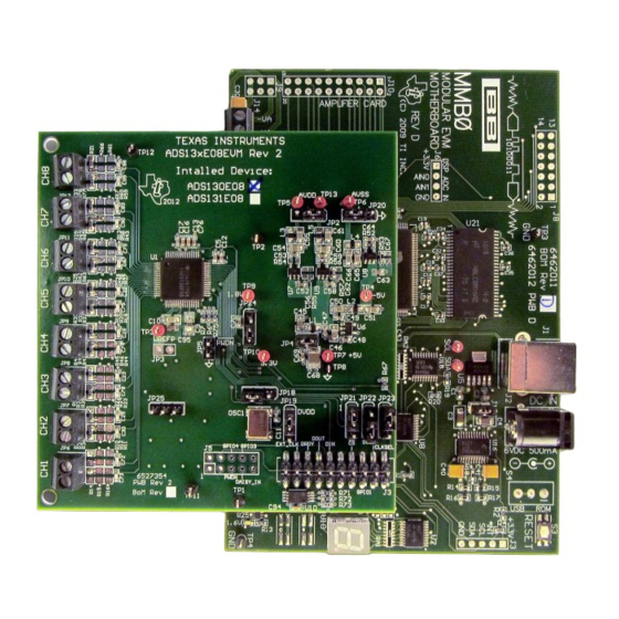
Performance Demonstration Kit for the ADS131E08
This user's guide describes the characteristics, operation, and use of the ADS131E08EVM-PDK. This
performance demonstration kit is an evaluation module for the ADS131E08, an eight-channel, 24-bit, low-
power, integrated analog front-end (AFE) designed for power protection circuits. The ADS131E08EVM-
PDK is intended for prototyping and evaluation. This user's guide includes a complete circuit description,
schematic diagram, and bill of materials.
Throughout this document, the terms ADS131E08EVM-PDK, demonstration kit, evaluation board,
evaluation module, and EVM are synonymous with the ADS131E08EVM.
The following related documents are available through the Texas Instruments web site at www.ti.com.
Pentium III, Celeron are registered trademarks of Intel Corporation.
Microsoft, Windows are registered trademarks of Microsoft Corporation.
SPI is a trademark of Motorola, Inc..
All other trademarks are the property of their respective owners.
SBAU200B – June 2012 – Revised February 2016
Submit Documentation Feedback
This datasheet has been downloaded from
Figure 1. ADS131E08EVM-PDK
Table 1. Related Documentation
Device
ADS131E08
Copyright © 2012–2016, Texas Instruments Incorporated
http://www.digchip.com
SBAU200B – June 2012 – Revised February 2016
Literature Number
SBAS561
Performance Demonstration Kit for the ADS131E08
at this
User's Guide
1
page
Advertisement
Table of Contents

Subscribe to Our Youtube Channel
Related Manuals for Texas Instruments ADS131E08


Summary of Contents for Texas Instruments ADS131E08
-
Page 1: Ads131E08Evm-Pdk
Figure 1. ADS131E08EVM-PDK This user's guide describes the characteristics, operation, and use of the ADS131E08EVM-PDK. This performance demonstration kit is an evaluation module for the ADS131E08, an eight-channel, 24-bit, low- power, integrated analog front-end (AFE) designed for power protection circuits. The ADS131E08EVM- PDK is intended for prototyping and evaluation. -
Page 2: Table Of Contents
Analog Supply Configurations ..............Digital Supply Configurations (DVDD and DGND) ....................... CLK Jumper Options ..................External Reference Jumper Options Performance Demonstration Kit for the ADS131E08 SBAU200B – June 2012 – Revised February 2016 Submit Documentation Feedback Copyright © 2012–2016, Texas Instruments Incorporated... - Page 3 Serial Interface Pinout ..............Register Assignments: Channel-Specific Settings ..................GPIO: General-Purpose I/O Register ..................... ADS131E08 Bill of Materials SBAU200B – June 2012 – Revised February 2016 Performance Demonstration Kit for the ADS131E08 Submit Documentation Feedback Copyright © 2012–2016, Texas Instruments Incorporated...
-
Page 4: Ads131E08Evm Overview
The ADS131E08EVM-PDK is intended for evaluating the ADS131E08 low-power, 24-bit, simultaneously- sampling, eight-channel analog-to-digital converter (ADC). The digital SPI™ control interface is provided by the MMB0 modular EVM motherboard that connects to the ADS131E08 evaluation board. The ADS131E08EVM-PDK is designed to expedite evaluation and system development. -
Page 5: Ads131E08Evm-Pdk Kit
Output connector: barrel plug (positive center), 2.5-mm I.D. x 5.5-mm O.D. (9-mm insertion depth) • Complies with applicable regional safety standards SBAU200B – June 2012 – Revised February 2016 Performance Demonstration Kit for the ADS131E08 Submit Documentation Feedback Copyright © 2012–2016, Texas Instruments Incorporated... -
Page 6: Software Installation
XP operating system with SP2, or Windows 7 operating system ® ® • Mouse or other pointing device • 1280 × 960 minimum display resolution Performance Demonstration Kit for the ADS131E08 SBAU200B – June 2012 – Revised February 2016 Submit Documentation Feedback Copyright © 2012–2016, Texas Instruments Incorporated... -
Page 7: Initialization Of Ads131E08Evm Gui
PC. Failure to observe this caution may cause Microsoft Windows to not recognize the ADS131E08EVM. Download the latest software from the TI website at www.ti.com/tool/ADS131E08EVM-PDK. To install the ADS131E08 software, unzip and run setup.exe. Figure 3 shows the initialization screen. -
Page 8: New Hardware Wizard Screen 1
Figure 6. New Hardware Wizard Screen 1 Click Next when the screen in Figure 7 appears. Figure 7. New Hardware Wizard Screen 2 Performance Demonstration Kit for the ADS131E08 SBAU200B – June 2012 – Revised February 2016 Submit Documentation Feedback Copyright © 2012–2016, Texas Instruments Incorporated... -
Page 9: New Hardware Wizard Screen 3
Click Next to find and install the driver. When the wizard is complete, the screen in Figure 9 appears. Figure 9. Completion of the First USB Driver SBAU200B – June 2012 – Revised February 2016 Performance Demonstration Kit for the ADS131E08 Submit Documentation Feedback Copyright © 2012–2016, Texas Instruments Incorporated... -
Page 10: Second New Hardware Wizard Screen
If so, click OK, close the GUI program, power cycle the ADS131E08EVM, and restart the newly installed ADS131E08 evaluation program. This process may need to be repeated if you plug the ADS131E08EVM-PDK into a different USB port on your computer. -
Page 11: Ads131E08Evm Daughter-Card Hardware Overview
J3. All other power supplies required for the front-end board are generated onboard by power management devices. The ADS131E08 operates in unipolar mode using a +3.0-V to +5.0-V analog supply (AVDD/AVSS) and a +1.8-V to +3.3-V digital supply (DVDD), or in bipolar mode using the onboard analog supply (±1.5 V to ±2.5 V). -
Page 12: Analog Supply Configurations
Don't care Don't care Don't care Don't care Don't care C48, C54, C59 Not installed Not installed Performance Demonstration Kit for the ADS131E08 SBAU200B – June 2012 – Revised February 2016 Submit Documentation Feedback Copyright © 2012–2016, Texas Instruments Incorporated... -
Page 13: Clk Jumper Options
The onboard oscillator is powered by the DVDD supply of the ADS131E08. Care must be taken to ensure that the external oscillator can operate either with +1.8 V or +3.3 V, depending on the DVDD supply configuration. - Page 14 DRDY EXT_CLK Analog Inputs The ADS131E08 provides users the option to feed in signals from any arbitrary signal source directly. Analog signals can be applied at terminal blocks J5 through J12. Performance Demonstration Kit for the ADS131E08 SBAU200B – June 2012 – Revised February 2016 Submit Documentation Feedback Copyright ©...
-
Page 15: Using The Software
Figure 12 shows the options available in the Save tab. Figure 12. File Save Option Under Save Tab SBAU200B – June 2012 – Revised February 2016 Performance Demonstration Kit for the ADS131E08 Submit Documentation Feedback Copyright © 2012–2016, Texas Instruments Incorporated... -
Page 16: Channel Registers Gui For The Configuration Registers
There are four tabs across the left side of the GUI; from top to bottom, they are: • About: Provides information about the EVM and software version revisions. • ADC Register: Includes all of the control registers for the ADS131E08 in a series of related subtabs: – Channel Registers – GPIO – Register Map •... -
Page 17: Channel Control Register Gui Panel: Single Channel Enabled
Figure 14. Channel Control Register GUI Panel: Single Channel Enabled Figure 15. Channel Control Registers GUI Panel: All Channels Enabled SBAU200B – June 2012 – Revised February 2016 Performance Demonstration Kit for the ADS131E08 Submit Documentation Feedback Copyright © 2012–2016, Texas Instruments Incorporated... -
Page 18: Example Of Internal Test Signals Viewed On The Scope Display Tab
Analysis→Scope Display tab, as Figure 16 shows. Figure 16. Example of Internal Test Signals Viewed on the Scope Display Tab Performance Demonstration Kit for the ADS131E08 SBAU200B – June 2012 – Revised February 2016 Submit Documentation Feedback Copyright © 2012–2016, Texas Instruments Incorporated... -
Page 19: Internal Temperature Sensor
Using the Software www.ti.com Temperature Sensor and the Scope Display Tab The internal temperature sensor on the ADS131E08 is shown in Figure 22. Temperature Sensor Monitor AVDD AVSS Figure 17. Internal Temperature Sensor When the internal mux is routed to the temperature sensor input, the output voltage of the ADC may be... -
Page 20: Gpio Control Register Gui Panel
Bit 0 GPIO GPIOD4 GPIOD3 GPIOD2 GPIOD1 GPIOC4 GPIOC3 GPIOC2 GPIOC1 Figure 19. GPIO Control Register GUI Panel Performance Demonstration Kit for the ADS131E08 SBAU200B – June 2012 – Revised February 2016 Submit Documentation Feedback Copyright © 2012–2016, Texas Instruments Incorporated... -
Page 21: Fault Status Indicator
EVM software on the Show/Poll Fault Status button, as shown in Figure Figure 20. Fault Status Indicator SBAU200B – June 2012 – Revised February 2016 Performance Demonstration Kit for the ADS131E08 Submit Documentation Feedback Copyright © 2012–2016, Texas Instruments Incorporated... -
Page 22: Device Register Settings
The Register→Device Register tab is a helpful debug feature that allows the user to view the state of all the internal registers. This tab is shown in Figure Figure 21. Device Register Settings Performance Demonstration Kit for the ADS131E08 SBAU200B – June 2012 – Revised February 2016 Submit Documentation Feedback Copyright © 2012–2016, Texas Instruments Incorporated... -
Page 23: Ads131E08 Analysis Tools
ADS131E08 Analysis Tools www.ti.com ADS131E08 Analysis Tools Under the Analysis tab in the ADS131E08 GUI software, there are three different analysis tools available that enable a detailed examination of the signals selected by the front-end mux: • Scope • Histogram •... -
Page 24: Scope Analysis Tab (Noise Levels For Each Channel Shown)
Signal-Zoom Analysis Options Figure 24. Zoom Option on the Waveform Examination Tool Performance Demonstration Kit for the ADS131E08 SBAU200B – June 2012 – Revised February 2016 Submit Documentation Feedback Copyright © 2012–2016, Texas Instruments Incorporated... -
Page 25: Histogram Bins
RMS voltage, and peak-to-peak voltage for analysis, as shown in Figure Figure 26. Statistics for the Signal Amplitude of Eight Channels SBAU200B – June 2012 – Revised February 2016 Performance Demonstration Kit for the ADS131E08 Submit Documentation Feedback Copyright © 2012–2016, Texas Instruments Incorporated... -
Page 26: Analysis→Fft Graph Of Normal Electrode Configuration
A frequency is a value that is calculated based on the sampling rate so that the coherent sampling criteria can be met. Performance Demonstration Kit for the ADS131E08 SBAU200B – June 2012 – Revised February 2016 Submit Documentation Feedback... -
Page 27: Analysis→Fft→Ac Analysis Parameters: Windowing Options
The SNR, THD, and harmonic information is listed in a table format. Figure 29. Analysis→FFT→FFT Analysis: Input Short Condition SBAU200B – June 2012 – Revised February 2016 Performance Demonstration Kit for the ADS131E08 Submit Documentation Feedback Copyright © 2012–2016, Texas Instruments Incorporated... -
Page 28: Changing The User-Defined Dynamic Range For Channel 1
This zoom function allows a closer examination of the FFT at frequencies of interest, as shown in Figure Figure 31. FFT Plot Using Waveform Zoom Function Performance Demonstration Kit for the ADS131E08 SBAU200B – June 2012 – Revised February 2016 Submit Documentation Feedback... -
Page 29: Bill Of Materials (Bom), Layout, And Schematic
Bill of Materials (BOM), Layout, and Schematic This section contains the complete BOM, printed circuit board (PCB) layouts, and schematic diagrams for the ADS131E08. NOTE: Board layouts are not to scale. These figures are intended to show how the board is laid out; they are not intended to be used for manufacturing ADS131E08 PCBs. - Page 30 Bill of Materials (BOM), Layout, and Schematic www.ti.com Table 11. ADS131E08 Bill of Materials (continued) Item Ref Des Description Manufacturer Part Number L1–L5 FERRITE BEAD 470 OHM 0805 Taiyo Yuden BK2125HM471-T R1, R67, R68, R69, R70 RES 0.0 OHM 1/10W 5% 0603 SMD...
- Page 31 Bill of Materials (BOM), Layout, and Schematic www.ti.com PCB Layout The ADS131E08 PCB layout is appended to this document. Front-End Board Schematic The ADS131E08 schematic is appended to this document. Revision History Changes from A Revision (February 2016) to B Revision .....................
- Page 32 STANDARD TERMS AND CONDITIONS FOR EVALUATION MODULES Delivery: TI delivers TI evaluation boards, kits, or modules, including any accompanying demonstration software, components, or documentation (collectively, an “EVM” or “EVMs”) to the User (“User”) in accordance with the terms and conditions set forth herein. Acceptance of the EVM is expressly subject to the following terms and conditions.
- Page 33 FCC Interference Statement for Class B EVM devices NOTE: This equipment has been tested and found to comply with the limits for a Class B digital device, pursuant to part 15 of the FCC Rules. These limits are designed to provide reasonable protection against harmful interference in a residential installation.
- Page 34 【無線電波を送信する製品の開発キットをお使いになる際の注意事項】 開発キットの中には技術基準適合証明を受けて いないものがあります。 技術適合証明を受けていないもののご使用に際しては、電波法遵守のため、以下のいずれかの 措置を取っていただく必要がありますのでご注意ください。 1. 電波法施行規則第6条第1項第1号に基づく平成18年3月28日総務省告示第173号で定められた電波暗室等の試験設備でご使用 いただく。 2. 実験局の免許を取得後ご使用いただく。 3. 技術基準適合証明を取得後ご使用いただく。 なお、本製品は、上記の「ご使用にあたっての注意」を譲渡先、移転先に通知しない限り、譲渡、移転できないものとします。 上記を遵守頂けない場合は、電波法の罰則が適用される可能性があることをご留意ください。 日本テキサス・イ ンスツルメンツ株式会社 東京都新宿区西新宿6丁目24番1号 西新宿三井ビル 3.3.3 Notice for EVMs for Power Line Communication: Please see http://www.tij.co.jp/lsds/ti_ja/general/eStore/notice_02.page 電力線搬送波通信についての開発キットをお使いになる際の注意事項については、次のところをご覧くださ い。http://www.tij.co.jp/lsds/ti_ja/general/eStore/notice_02.page SPACER EVM Use Restrictions and Warnings: 4.1 EVMS ARE NOT FOR USE IN FUNCTIONAL SAFETY AND/OR SAFETY CRITICAL EVALUATIONS, INCLUDING BUT NOT LIMITED TO EVALUATIONS OF LIFE SUPPORT APPLICATIONS.
- Page 35 Notwithstanding the foregoing, any judgment may be enforced in any United States or foreign court, and TI may seek injunctive relief in any United States or foreign court. Mailing Address: Texas Instruments, Post Office Box 655303, Dallas, Texas 75265 Copyright © 2015, Texas Instruments Incorporated...
- Page 36 IMPORTANT NOTICE Texas Instruments Incorporated and its subsidiaries (TI) reserve the right to make corrections, enhancements, improvements and other changes to its semiconductor products and services per JESD46, latest issue, and to discontinue any product or service per JESD48, latest issue.
- Page 37 Mouser Electronics Authorized Distributor Click to View Pricing, Inventory, Delivery & Lifecycle Information: Texas Instruments ADS131E08EVM-PDK...
Need help?
Do you have a question about the ADS131E08 and is the answer not in the manual?
Questions and answers