Table of Contents
Advertisement
Quick Links
Performance Demonstration Kit for the ADS131E08
This user's guide describes the characteristics, operation, and use of the ADS131E08EVM-PDK. This
performance demonstration kit is an evaluation module for the ADS131E08, an eight-channel, 24-bit, low-
power, integrated analog front-end (AFE) designed for power protection circuits. The ADS131E08EVM-
PDK is intended for prototyping and evaluation. This user's guide includes a complete circuit description,
schematic diagram, and bill of materials.
Throughout this document, the terms ADS131E08EVM-PDK, demonstration kit, evaluation board,
evaluation module, and EVM are synonymous with the ADS131E08EVM.
The following related documents are available through the Texas Instruments web site at www.ti.com.
Pentium III, Celeron are registered trademarks of Intel Corporation.
Windows is a registered trademark of Microsoft.
SPI is a trademark of Motorola, Inc..
All other trademarks are the property of their respective owners.
SBAU200 – June 2012
Submit Documentation Feedback
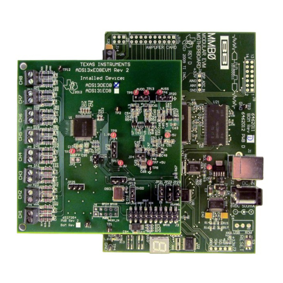
Figure 1. ADS131E08EVM-PDK
Related Documentation
Device
ADS131E08
Copyright © 2012, Texas Instruments Incorporated
Literature Number
SBAS561
Performance Demonstration Kit for the ADS131E08
User's Guide
SBAU200 – June 2012
1
Advertisement
Table of Contents

Subscribe to Our Youtube Channel
Related Manuals for Texas Instruments ADS131E08


Summary of Contents for Texas Instruments ADS131E08
-
Page 1: Ads131E08Evm-Pdk
Figure 1. ADS131E08EVM-PDK This user's guide describes the characteristics, operation, and use of the ADS131E08EVM-PDK. This performance demonstration kit is an evaluation module for the ADS131E08, an eight-channel, 24-bit, low- power, integrated analog front-end (AFE) designed for power protection circuits. The ADS131E08EVM- PDK is intended for prototyping and evaluation. -
Page 2: Table Of Contents
Digital Supply Configurations (DVDD and DGND) ...................... CLK Jumper Options ..................External Reference Jumper Options ..............Auxiliary Connector Test Signals and Test Points Performance Demonstration Kit for the ADS131E08 SBAU200 – June 2012 Submit Documentation Feedback Copyright © 2012, Texas Instruments Incorporated... - Page 3 ....................Serial Interface Pinout ..............Register Assignments: Channel-Specific Settings ................... GPIO: General-Purpose I/O Register .................... ADS131E08 Bill of Materials SBAU200 – June 2012 Performance Demonstration Kit for the ADS131E08 Submit Documentation Feedback Copyright © 2012, Texas Instruments Incorporated...
-
Page 4: Ads131E08Evm Overview
The ADS131E08EVM-PDK is intended for evaluating the ADS131E08 low-power, 24-bit, simultaneously- sampling, eight-channel analog-to-digital converter (ADC). The digital SPI™ control interface is provided by the MMB0 modular EVM motherboard that connects to the ADS131E08 evaluation board. The ADS131E08EVM-PDK is designed to expedite evaluation and system development. -
Page 5: Ads131E08Evm-Pdk Kit
The complete kit includes the following items: • ADS131E08EVM printed circuit board (PCB) • MMB0 (modular EVM motherboard) • 6 V at 3 A wall wart SBAU200 – June 2012 Performance Demonstration Kit for the ADS131E08 Submit Documentation Feedback Copyright © 2012, Texas Instruments Incorporated... -
Page 6: Software Installation
XP operating system with SP2, or Windows 7 operating system ® • Mouse or other pointing device • 1280 × 960 minimum display resolution Performance Demonstration Kit for the ADS131E08 SBAU200 – June 2012 Submit Documentation Feedback Copyright © 2012, Texas Instruments Incorporated... -
Page 7: Initialization Of Ads131E08Evm Gui
PC. Failure to observe this caution may cause Microsoft Windows to not recognize the ADS131E08EVM. Download the latest software from the TI website at www.ti.com/tool/ADS131E08EVM-PDK. To install the ADS131E08 software, unzip and run setup.exe. Figure 3 shows the initialization screen. -
Page 8: New Hardware Wizard Screen 1
Figure 6. New Hardware Wizard Screen 1 Click Next when the screen in Figure 7 appears. Figure 7. New Hardware Wizard Screen 2 Performance Demonstration Kit for the ADS131E08 SBAU200 – June 2012 Submit Documentation Feedback Copyright © 2012, Texas Instruments Incorporated... -
Page 9: New Hardware Wizard Screen 3
Click Next to find and install the driver. When the wizard is complete, the screen in Figure 9 appears. Figure 9. Completion of the First USB Driver SBAU200 – June 2012 Performance Demonstration Kit for the ADS131E08 Submit Documentation Feedback Copyright © 2012, Texas Instruments Incorporated... -
Page 10: Second New Hardware Wizard Screen
If so, click OK, close the GUI program, power cycle the ADS131E08EVM, and restart the newly installed ADS131E08 evaluation program. This process may need to be repeated if you plug the ADS131E08EVM-PDK into a different USB port on your computer. -
Page 11: Ads131E08Evm Daughter-Card Hardware Overview
J3. All other power supplies required for the front-end board are generated onboard by power management devices. The ADS131E08 operates in unipolar mode using a +3.0-V to +5.0-V analog supply (AVDD/AVSS) and a +1.8-V to +3.3-V digital supply (DVDD), or in bipolar mode using the onboard analog supply (±1.5 V to ±2.5 V). -
Page 12: Analog Supply Configurations
Don't care Don't care Don't care Don't care Don't care Don't care Don't care C48, C54, C59 Not installed Not installed Performance Demonstration Kit for the ADS131E08 SBAU200 – June 2012 Submit Documentation Feedback Copyright © 2012, Texas Instruments Incorporated... -
Page 13: Clk Jumper Options
The onboard oscillator is powered by the DVDD supply of the ADS131E08. Care must be taken to ensure that the external oscillator can operate either with +1.8 V or +3.3 V, depending on the DVDD supply configuration. -
Page 14: Serial Interface Pinout
DRDY EXT_CLK Analog Inputs The ADS131E08 provides users the option to feed in signals from any arbitrary signal source directly. Analog signals can be applied at terminal blocks J5 through J12. Performance Demonstration Kit for the ADS131E08 SBAU200 – June 2012 Submit Documentation Feedback Copyright ©... -
Page 15: Using The Software
File menu. Figure 12 shows the options available in the Save tab. Figure 12. File Save Option Under Save Tab SBAU200 – June 2012 Performance Demonstration Kit for the ADS131E08 Submit Documentation Feedback Copyright © 2012, Texas Instruments Incorporated... -
Page 16: Channel Registers Gui For The Configuration Registers
There are four tabs across the left side of the GUI; from top to bottom, they are: • About: Provides information about the EVM and software version revisions. • ADC Register: Includes all of the control registers for the ADS131E08 in a series of related subtabs: – Channel Registers – GPIO – Register Map •... -
Page 17: Channel Control Register Gui Panel: Single Channel Enabled
MUX80 Figure 14. Channel Control Register GUI Panel: Single Channel Enabled Figure 15. Channel Control Registers GUI Panel: All Channels Enabled SBAU200 – June 2012 Performance Demonstration Kit for the ADS131E08 Submit Documentation Feedback Copyright © 2012, Texas Instruments Incorporated... -
Page 18: Example Of Internal Test Signals Viewed On The Scope Display Tab
(PGA), and the ADC. The test signals may be viewed on the Analysis→Scope Display tab, as Figure 16 shows. Figure 16. Example of Internal Test Signals Viewed on the Scope Display Tab Performance Demonstration Kit for the ADS131E08 SBAU200 – June 2012 Submit Documentation Feedback Copyright © 2012, Texas Instruments Incorporated... -
Page 19: Internal Temperature Sensor
USING THE SOFTWARE www.ti.com Temperature Sensor and the Scope Display Tab The internal temperature sensor on the ADS131E08 is shown in Figure 22. Temperature Sensor Monitor AVDD AVSS Figure 17. Internal Temperature Sensor When the internal mux is routed to the temperature sensor input, the output voltage of the ADC may be... -
Page 20: Gpio Control Register Gui Panel
Bit 2 Bit 1 Bit 0 GPIO GPIOD4 GPIOD3 GPIOD2 GPIOD1 GPIOC4 GPIOC3 GPIOC2 GPIOC1 Figure 19. GPIO Control Register GUI Panel Performance Demonstration Kit for the ADS131E08 SBAU200 – June 2012 Submit Documentation Feedback Copyright © 2012, Texas Instruments Incorporated... -
Page 21: Fault Status Indicator
EVM software on the Show/Poll Fault Status button, as shown in Figure Figure 20. Fault Status Indicator SBAU200 – June 2012 Performance Demonstration Kit for the ADS131E08 Submit Documentation Feedback Copyright © 2012, Texas Instruments Incorporated... -
Page 22: Device Register Settings
The Register→Device Register tab is a helpful debug feature that allows the user to view the state of all the internal registers. This tab is shown in Figure Figure 21. Device Register Settings Performance Demonstration Kit for the ADS131E08 SBAU200 – June 2012 Submit Documentation Feedback Copyright © 2012, Texas Instruments Incorporated... -
Page 23: Ads131E08 Analysis Tools
ADS131E08 ANALYSIS TOOLS www.ti.com ADS131E08 ANALYSIS TOOLS Under the Analysis tab in the ADS131E08 GUI software, there are three different analysis tools available that enable a detailed examination of the signals selected by the front-end mux: • Scope • Histogram •... -
Page 24: Scope Analysis Tab (Noise Levels For Each Channel Shown)
Figure 24 shows an example of the waveform examination tool. Signal-Zoom Analysis Options Figure 24. Zoom Option on the Waveform Examination Tool Performance Demonstration Kit for the ADS131E08 SBAU200 – June 2012 Submit Documentation Feedback Copyright © 2012, Texas Instruments Incorporated... -
Page 25: Histogram Bins
RMS voltage, and peak-to-peak voltage for analysis, as shown in Figure Figure 26. Statistics for the Signal Amplitude of Eight Channels SBAU200 – June 2012 Performance Demonstration Kit for the ADS131E08 Submit Documentation Feedback Copyright © 2012, Texas Instruments Incorporated... -
Page 26: Analysis→Fft Graph Of Normal Electrode Configuration
A frequency is a value that is calculated based on the sampling rate so that the coherent sampling criteria can be met. Performance Demonstration Kit for the ADS131E08 SBAU200 – June 2012 Submit Documentation Feedback Copyright © 2012, Texas Instruments Incorporated... -
Page 27: Analysis→Fft→Ac Analysis Parameters: Windowing Options
The SNR, THD, and harmonic information is listed in a table format. Figure 29. Analysis→FFT→FFT Analysis: Input Short Condition SBAU200 – June 2012 Performance Demonstration Kit for the ADS131E08 Submit Documentation Feedback Copyright © 2012, Texas Instruments Incorporated... -
Page 28: Changing The User-Defined Dynamic Range For Channel 1
This zoom function allows a closer examination of the FFT at frequencies of interest, as shown in Figure Figure 31. FFT Plot Using Waveform Zoom Function Performance Demonstration Kit for the ADS131E08 SBAU200 – June 2012 Submit Documentation Feedback Copyright © 2012, Texas Instruments Incorporated... -
Page 29: Bill Of Materials (Bom), Layout, And Schematic
ADS131E08. NOTE: Board layouts are not to scale. These figures are intended to show how the board is laid out; they are not intended to be used for manufacturing ADS131E08 PCBs. SBAU200 – June 2012 Performance Demonstration Kit for the ADS131E08 Submit Documentation Feedback Copyright ©... -
Page 30: Ads131E08 Bill Of Materials
BILL OF MATERIALS (BOM), LAYOUT, AND SCHEMATIC www.ti.com Bill of Materials Table 10 lists the bill of materials for the ADS131E08. Table 10. ADS131E08 Bill of Materials Item Ref Des Description Manufacturer Part Number Printed Circuit Board 6527354 C1, C2, C3, C4, C5, C6, C11, C17, C39,... - Page 31 BILL OF MATERIALS (BOM), LAYOUT, AND SCHEMATIC www.ti.com Table 10. ADS131E08 Bill of Materials (continued) Item Ref Des Description Manufacturer Part Number R5, R6, R8, R9, R11, R12, R14, R15, R17, Not Installed R18, R20, R21, R23, R24, R26, R27, R29,...
- Page 32 BILL OF MATERIALS (BOM), LAYOUT, AND SCHEMATIC www.ti.com PCB Layout The ADS131E08 PCB layout is appended to this document. Front-End Board Schematic The ADS131E08 schematic is appended to this document. Performance Demonstration Kit for the ADS131E08 SBAU200 – June 2012 Submit Documentation Feedback Copyright ©...
- Page 33 Top Assembly Top Layer...
- Page 34 Internal Layer 1 Internal Layer 2...
- Page 35 Bottom Layer Bottom Assembly...
- Page 36 AVDD AVSS AVDD AVDD AVSS AVDD AVDD AVSS AVDD IN1N IN3N IN2N 470pF 470pF 470pF AVSS AVSS AVSS AVSS AVSS AVSS AVDD AVSS AVDD AVDD AVSS AVDD AVDD AVSS AVDD IN1P IN3P IN2P 470pF 470pF AVSS 470pF AVSS AVSS AVSS AVSS AVSS AVDD...
- Page 37 TP15 TP14 TP16 GPIO1 GPIO2 AVSS GPIO3 /PWDN VCAP3 GPIO4 DAISY_IN AVDD 0.1uF AGND AVSS DVDD AVDD AVDD AVDD ADS13xE08 AGND CLKSEL 0.1uF CLKSEL CLKSEL IN8N IN8N DGND IN8P IN8P DVDD IN7N AVSS AVSS IN7N AVSS AGND IN7P IN7P DGND IN6N IN6N DVDD...
- Page 38 External Reference External Reference Drivers AVDD TEMP AVDD TRIM AVSS C33 NI AGND AVSS VREFP JP12 AVDD C34 NI TEMP AGND TRIM AVSS AVSS AVSS NOT INSTALLED 12500 TI Boulevard. Dallas, Texas 75243 Title: ADS13xE08 Engineer: Tom Hendrick DOCUMENTCONTROL # REV: Drawn By: Tom Hendrick...
- Page 39 VCC_5v VCC_-5v 470uH 470uH 10uF 10uF 10uF 10uF AGND AGND TPS60403 AGND AGND AGND +3.0V 470uH AVDD 2.2uF 10uF 10uF AGND AGND AGND NR/FB TPS73230 AGND 0.1uF AGND AGND TP13 +2.5V 470uH 2.2uF 10uF 10uF AGND 49.9K AGND AGND NR/FB TPS73201 AGND 46.4K...
- Page 40 DVDD DVDD C63 100uF AGND 0.1uF JP10 CLKSEL JP11 VCC_5v VCC_1.8V SPI_CLK TP10 SPI_CS VCC_3.3V GPIO1 /RESET SPI_IN GPIO2 SPI_OUT 100uF 0.1uF SPI_DRDY VCC_3.3V EXT_CLK 0.1uF VCC_3.3V Dummy Connector SPI_START AGND 24AA256-I/ST AGND 12500 TI Boulevard. Dallas, Texas 75243 Title: ADS13xE08 Engineer: Tom Hendrick...
- Page 41 Evaluation Board/Kit Important Notice Texas Instruments (TI) provides the enclosed product(s) under the following conditions: This evaluation board/kit is intended for use for ENGINEERING DEVELOPMENT, DEMONSTRATION, OR EVALUATION PURPOSES ONLY and is not considered by TI to be a finished end-product fit for general consumer use. Persons handling the product(s) must have electronics training and observe good engineering practice standards.
- Page 42 Any exceptions to this are strictly prohibited and unauthorized by Texas Instruments unless user has obtained appropriate experimental/development licenses from local regulatory authorities, which is responsibility of user including its acceptable authorization.
- Page 43 FCC Interference Statement for Class B EVM devices This equipment has been tested and found to comply with the limits for a Class B digital device, pursuant to part 15 of the FCC Rules. These limits are designed to provide reasonable protection against harmful interference in a residential installation. This equipment generates, uses and can radiate radio frequency energy and, if not installed and used in accordance with the instructions, may cause harmful interference to radio communications.
- Page 44 Also, please do not transfer this product, unless you give the same notice above to the transferee. Please note that if you could not follow the instructions above, you will be subject to penalties of Radio Law of Japan. Texas Instruments Japan Limited (address) 24-1, Nishi-Shinjuku 6 chome, Shinjuku-ku, Tokyo, Japan http://www.tij.co.jp...
- Page 45 FDA Class III or similar classification, then you must specifically notify TI of such intent and enter into a separate Assurance and Indemnity Agreement. Mailing Address: Texas Instruments, Post Office Box 655303, Dallas, Texas 75265 Copyright © 2012, Texas Instruments Incorporated...
- Page 46 IMPORTANT NOTICE Texas Instruments Incorporated and its subsidiaries (TI) reserve the right to make corrections, enhancements, improvements and other changes to its semiconductor products and services per JESD46, latest issue, and to discontinue any product or service per JESD48, latest issue.
- Page 47 Mouser Electronics Authorized Distributor Click to View Pricing, Inventory, Delivery & Lifecycle Information: Texas Instruments ADS131E08EVM-PDK...
Need help?
Do you have a question about the ADS131E08 and is the answer not in the manual?
Questions and answers