Table of Contents
Advertisement
Quick Links
This user's guide describes the characteristics, operation, and use of the ADS131M04 evaluation module
(EVM). This kit is an evaluation platform for the ADS131M04, which is a 4-channel, simultaneously-
sampling, 24-bit, delta-sigma (ΔΣ) analog-to-digital converter (ADC). The ADS131M04 offers wide
dynamic range and internal calibration features, making the device excellent for energy metering, power
quality, protection relay, and circuit breaker applications.
The ADS131M04EVM eases the evaluation of the device with hardware, software, and computer
connectivity through the universal serial bus (USB) interface. This user's guide includes complete circuit
descriptions, schematic diagrams, and a bill of materials. Throughout this document, the abbreviation EVM
and the term evaluation module are synonymous with the ADS131M04EVM. The following related
documents are available through the Texas Instruments web site at www.ti.com.
SBAU332A – March 2019 – Revised June 2019
Submit Documentation Feedback
ADS131M04 Evaluation Module
Table 1. Related Documentation
Device
ADS131M04
Copyright © 2019, Texas Instruments Incorporated
SBAU332A – March 2019 – Revised June 2019
Literature Number
SBAS890
ADS131M04 Evaluation Module
User's Guide
1
Advertisement
Table of Contents

Subscribe to Our Youtube Channel
Related Manuals for Texas Instruments ADS131M04


Summary of Contents for Texas Instruments ADS131M04
-
Page 1: Related Documentation
This user's guide describes the characteristics, operation, and use of the ADS131M04 evaluation module (EVM). This kit is an evaluation platform for the ADS131M04, which is a 4-channel, simultaneously- sampling, 24-bit, delta-sigma (ΔΣ) analog-to-digital converter (ADC). The ADS131M04 offers wide dynamic range and internal calibration features, making the device excellent for energy metering, power quality, protection relay, and circuit breaker applications. -
Page 2: Table Of Contents
PHI Connector Pin Functions ......................Digital Header Pins ....................LaunchPad™ Pin Functions ......................Default Settings ..................ADS131M04EVM Bill of Materials ADS131M04 Evaluation Module SBAU332A – March 2019 – Revised June 2019 Submit Documentation Feedback Copyright © 2019, Texas Instruments Incorporated... - Page 3 Trademarks LaunchPad, BoosterPack are trademarks of Texas Instruments. Windows is a registered trademark of Microsoft. LabVIEW is a trademark of National Instruments. All other trademarks are the property of their respective owners. SBAU332A – March 2019 – Revised June 2019...
-
Page 4: Evm Overview
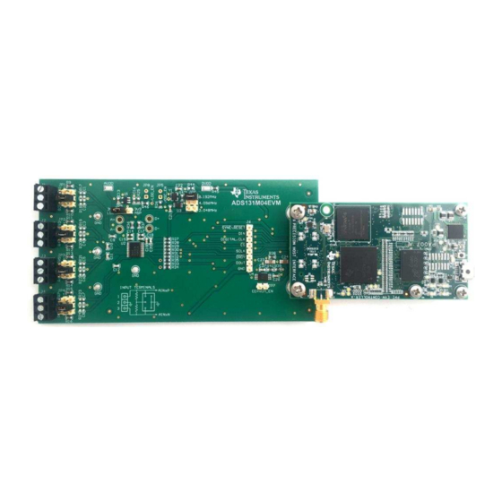
EVM Overview The ADS131M04EVM is a platform for evaluating the performance of the ADS131M04, which is a 4- channel, simultaneously-sampling, 24-bit, ΔΣ ADC. The evaluation kit includes the ADS131M04EVM board and the precision host interface (PHI) controller board that enables the accompanying computer software to communicate with the ADC over the USB for data capture and analysis. -
Page 5: Evm Analog Interface
49.9-Ω resistors on each input. An input must not be applied such that the voltage on the input pins of the ADS131M04 exceeds the absolute maximum ratings. See the ADS131M04 data sheet for details. -
Page 6: Input Terminal Blocks And Headers (Pcb)
Channel 2 negative input AIN2N Channel 3 positive input AIN3P EVM ground AGND and DGND Channel 3 negative input AIN3N ADS131M04 Evaluation Module SBAU332A – March 2019 – Revised June 2019 Submit Documentation Feedback Copyright © 2019, Texas Instruments Incorporated... -
Page 7: Clkin External Clock (Pcb)
Short negative input to ground ADC External Clock (CLKIN) Options The ADS131M04 requires a continuous, free-running external master clock at the CLKIN pin for normal operation. The onboard complementary metal oxide semiconductor (CMOS) crystal oscillator (Y1) provides the nominal 8.192-MHz clock frequency used in the high-resolution (HR) mode of the device. -
Page 8: Digital Interface
Section 1, the EVM interfaces with the PHI and communicates with the computer over the USB. There are two devices on the EVM with which the PHI communicates: the ADS131M04 ADC (over SPI) and the EEPROM (over I C). The EEPROM comes pre-programmed with the information required to configure and initialize the ADS131M04EVM platform. -
Page 9: Digital Header Pins
In addition to the PHI, the EVM has a header connected to the digital lines that can be used to connect a logic analyzer or oscilloscope. This placement allows for easy access to the digital communications. Header J6 is connected to the digital lines between the ADS131M04 and the PHI connector. Table 6 describes the digital header pins. -
Page 10: Power Supplies
DVDD can be driven externally from the DVDD test point at TP1 if R45 is removed from the EVM. ADS131M04 Evaluation Module SBAU332A – March 2019 – Revised June 2019 Submit Documentation Feedback Copyright © 2019, Texas Instruments Incorporated... -
Page 11: Ads131M04Evm Initial Setup
The default position of the JP6 jumper is across [1-2] at the top. JP6 sets the onboard oscillator frequency to 8.192 MHz, used for the ADS131M04 in high-resolution mode. The default connection for JP9 is to the left, so that the linear regulator is powering the system using 5 V from the PHI controller. -
Page 12: Ads131M04 Software Installation Prompts
Figure 6 to complete the installation. Figure 6. ADS131M04 Software Installation Prompts As a part of the ADS131M04EVM GUI installation, a prompt with a Device Driver Installation (as shown in Figure 7) appears on the screen. Click Next to proceed. -
Page 13: Labview Run-Time Engine Installation
The ADS131M04EVM requires the LabVIEW™ run-time engine and may prompt for the installation of this software, as shown in Figure 8, if not already installed. Figure 8. LabVIEW Run-Time Engine Installation SBAU332A – March 2019 – Revised June 2019 ADS131M04 Evaluation Module Submit Documentation Feedback Copyright © 2019, Texas Instruments Incorporated... -
Page 14: Ads131M04Evm Operation
ADS131M04EVM Operation www.ti.com Verify that C:\Program Files (x86)\Texas Instruments\ADS131M04EVM is as shown in Figure 9 after these installations. Figure 9. ADS131M04EVM GUI Folder Post-Installation ADS131M04EVM Operation The following instructions are a step-by-step guide to connecting the ADS131M04EVM to the computer and evaluating the performance of the ADS131M04: 1. -
Page 15: Launch The Evm Gui Software
ADS131M04EVM Operation www.ti.com Figure 11 shows how to launch the ADS131M04EVM GUI software. Figure 11. Launch the EVM GUI Software SBAU332A – March 2019 – Revised June 2019 ADS131M04 Evaluation Module Submit Documentation Feedback Copyright © 2019, Texas Instruments Incorporated... -
Page 16: Evm Gui Global Input Parameters
ADS131M04. This section also sets the data rate by setting the oversampling ratio (OSR) in the ADC. Finally, this section may used to set the power modes in the registers. The ADS131M04 can be set to high-resolution, low power, and very-low power modes in conjunction with the jumper settings of... -
Page 17: Register Map Configuration
ADS131M04EVM Operation www.ti.com Register Map Configuration Tool The register map configuration tool allows the user to view and modify the registers of the ADS131M04. This tool can be selected, as indicated in Figure 13, by clicking on the Register Map Config radio button at the Pages section of the left pane. -
Page 18: Time Domain Display Tool Options
Analysis tools described in the subsequent sections causes calculations to be performed on the same set of data. Figure 14. Time Domain Display Tool Options ADS131M04 Evaluation Module SBAU332A – March 2019 – Revised June 2019 Submit Documentation Feedback Copyright © 2019, Texas Instruments Incorporated... -
Page 19: Spectral Analysis Tool
The spectral analysis tool, shown in Figure 15, is intended to evaluate the dynamic performance (SNR, THD, SFDR, SINAD, and ENOB) of the ADS131M04 ADC through single-tone sinusoidal signal FFT analysis using the 7-term Blackman-Harris window setting. Figure 15. Spectral Analysis Tool The FFT tool includes windowing options that are required to mitigate the effects of non-coherent sampling (this discussion is beyond the scope of this document). -
Page 20: Histogram Analysis Tool
16, the histogram corresponding to a DC input is displayed on clicking the Capture button. Figure 16. Histogram Analysis Tool ADS131M04 Evaluation Module SBAU332A – March 2019 – Revised June 2019 Submit Documentation Feedback Copyright © 2019, Texas Instruments Incorporated... -
Page 21: Ads131M04Evm Bill Of Materials, Pcb Layout, And Schematic
R9, R10, R11, R12, R13, 49.9 RES, 49.9, 1%, 0.1 W, AEC-Q200 Grade 0, 0603 0603 CRCW060349R9FKEA Vishay-Dale R14, R15, R16 SBAU332A – March 2019 – Revised June 2019 ADS131M04 Evaluation Module Submit Documentation Feedback Copyright © 2019, Texas Instruments Incorporated... - Page 22 Connector, Receptacle, 100mil, 10x2, Gold J7, J8 10x2 Receptacle SSW-110-22-F-D-VS-K Samtec plated, SMD JP5, JP8 Header, 100mil, 2x1, Gold, TH 2x1 Header TSW-102-07-G-S Samtec ADS131M04 Evaluation Module SBAU332A – March 2019 – Revised June 2019 Submit Documentation Feedback Copyright © 2019, Texas Instruments Incorporated...
- Page 23 RES, 0, 5%, 0.1 W, 0603 0603 RC0603JR-070RL Yageo TP7, TP8, Terminal, Turret, TH, Double Keystone1573-2 1573-2 Keystone TP9, TP10 SBAU332A – March 2019 – Revised June 2019 ADS131M04 Evaluation Module Submit Documentation Feedback Copyright © 2019, Texas Instruments Incorporated...
-
Page 24: Top Silkscreen
Figure 22 illustrate the ADS131M04EVM PCB layout. Figure 17. Top Silkscreen Figure 18. Top Layer Figure 19. Ground Layer 1 ADS131M04 Evaluation Module SBAU332A – March 2019 – Revised June 2019 Submit Documentation Feedback Copyright © 2019, Texas Instruments Incorporated... -
Page 25: Ground Layer 2
ADS131M04EVM Bill of Materials, PCB Layout, and Schematic www.ti.com Figure 20. Ground Layer 2 Figure 21. Bottom Layer Figure 22. Bottom Silkscreen SBAU332A – March 2019 – Revised June 2019 ADS131M04 Evaluation Module Submit Documentation Feedback Copyright © 2019, Texas Instruments Incorporated... -
Page 26: Ads131M04Evm Hardware Schematic
ADS131M04EVM Bill of Materials, PCB Layout, and Schematic www.ti.com Schematic Figure 23 Figure 24 illustrate the ADS131M04EVM schematics. Figure 23. ADS131M04EVM Hardware Schematic ADS131M04 Evaluation Module SBAU332A – March 2019 – Revised June 2019 Submit Documentation Feedback Copyright © 2019, Texas Instruments Incorporated... -
Page 27: Ads131M04Evm Main Schematic
EVM_DVDD 3V3_LP 5V_LP EVM_RAW_5V ADC_DIGITAL.CLK DNPC25 DNPC26 ADC_DIGITAL.SYNC/RESET 10uF 10uF ADC_DIGITAL.CS ADC_DIGITAL.DRDY ADC_DIGITAL.DIN ADC_DIGITAL.SCLK ADC_DIGITAL.DOUT Figure 24. ADS131M04EVM Main Schematic SBAU332A – March 2019 – Revised June 2019 ADS131M04 Evaluation Module Submit Documentation Feedback Copyright © 2019, Texas Instruments Incorporated... - Page 28 NOTE: Page numbers for previous revisions may differ from page numbers in the current version. Changes from Original (March 2019) to A Revision ....................... Page ................• Changed document to align with new evaluation module Revision History SBAU332A – March 2019 – Revised June 2019 Submit Documentation Feedback Copyright © 2019, Texas Instruments Incorporated...
- Page 29 STANDARD TERMS FOR EVALUATION MODULES Delivery: TI delivers TI evaluation boards, kits, or modules, including any accompanying demonstration software, components, and/or documentation which may be provided together or separately (collectively, an “EVM” or “EVMs”) to the User (“User”) in accordance with the terms set forth herein.
- Page 30 www.ti.com Regulatory Notices: 3.1 United States 3.1.1 Notice applicable to EVMs not FCC-Approved: FCC NOTICE: This kit is designed to allow product developers to evaluate electronic components, circuitry, or software associated with the kit to determine whether to incorporate such items in a finished product and software developers to write software applications for use with the end product.
- Page 31 www.ti.com Concernant les EVMs avec antennes détachables Conformément à la réglementation d'Industrie Canada, le présent émetteur radio peut fonctionner avec une antenne d'un type et d'un gain maximal (ou inférieur) approuvé pour l'émetteur par Industrie Canada. Dans le but de réduire les risques de brouillage radioélectrique à...
- Page 32 www.ti.com EVM Use Restrictions and Warnings: 4.1 EVMS ARE NOT FOR USE IN FUNCTIONAL SAFETY AND/OR SAFETY CRITICAL EVALUATIONS, INCLUDING BUT NOT LIMITED TO EVALUATIONS OF LIFE SUPPORT APPLICATIONS. 4.2 User must read and apply the user guide and other available documentation provided by TI regarding the EVM prior to handling or using the EVM, including without limitation any warning or restriction notices.
- Page 33 Notwithstanding the foregoing, any judgment may be enforced in any United States or foreign court, and TI may seek injunctive relief in any United States or foreign court. Mailing Address: Texas Instruments, Post Office Box 655303, Dallas, Texas 75265 Copyright © 2019, Texas Instruments Incorporated...
- Page 34 TI products. TI’s provision of these resources does not expand or otherwise alter TI’s applicable warranties or warranty disclaimers for TI products. Mailing Address: Texas Instruments, Post Office Box 655303, Dallas, Texas 75265 Copyright © 2019, Texas Instruments Incorporated...
Need help?
Do you have a question about the ADS131M04 and is the answer not in the manual?
Questions and answers