Honeywell BENDIX/KING KAP 140 Maintenance Manual
Flight control system
Hide thumbs
Also See for BENDIX/KING KAP 140:
- Manual (102 pages) ,
- Pilot's manual (137 pages) ,
- Installation manual (32 pages)

Related Manuals for Honeywell BENDIX/KING KAP 140


Summary of Contents for Honeywell BENDIX/KING KAP 140
- Page 1 FLIGHTLINE MAINTENANCE MANUAL KAP 140 FLIGHT CONTROL SYSTEM MANUAL NUMBER 006- -15574- -0002 REVISION 2 DEC, 2002...
- Page 2 Reproduction of this publication or any portion thereof by any means without the express writ- ten permission of Honeywell is prohibited. For further information contact the Manager, Techni- cal Publications, Honeywell, One Technology Center, 23500 West 105th Street Olathe KS...
- Page 3 BENDIX/KING KAP 140 REVISION HISTORY DATE CHANGES October, 1998 Initial Release April, 2002 Add unit versions --2603, --5403, --7703 December, 2002 Add unit versions --2704, --5504, --7904 Revision 2, Dec/2002 RH--1 CS:15574F02.IDU...
- Page 4 BENDIX/KING KAP 140 THIS PAGE IS RESERVED Revision 2, Dec/2002 RH--2 CS:15574F02.IDU...
- Page 5 BENDIX/KING KAP 140 SECTION I GENERAL INFORMATION Paragraph Page 1. 1 I NTRO DUCTI O N ........... 1 - - 1 1.
-
Page 6: Table Of Contents
BENDIX/KING KAP 140 SECTION II SYSTEM OPERATION Paragraph Page 2. 1 G ENERAL ............2- - 1 2. - Page 7 BENDIX/KING KAP 140 SECTION III REMOTE TERMINAL INTERFACE Paragraph Page 3. 1 G ENERAL ............3- - 1 3.
- Page 8 BENDIX/KING KAP 140 SECTION IV TROUBLESHOOTING Paragraph Page 4. 1 G ENERAL ............4- - 1 4.
- Page 9 BENDIX/KING KAP 140 LIST OF ILLUSTRATIONS Figure Page 1 -- 1 KAP 140 SYSTEM BLO CK DI AG RAM ....... . . 1 -- 5 1 -- 2 KC 140 FLIGHT CONTROL COMPUTER...
- Page 10 BENDIX/KING KAP 140 BLANK PAGE MARKER (NEW) Revision 2, Dec/2002 CS:15574F02.IDU...
- Page 11 BENDIX/KING KAP 140 SECTION I GENERAL INFORMATION 1.1 INTRODUCTION This manual provides general system maintenance instructions and theory of operation for the KAP 140 Automatic Flight Control System. This manual is intended to be a supplement to an aircraft level maintenance manual specific to a particular aircraft type. The information provided here is to assist in flight line check--out and troubleshooting of suspected problems in the KAP 140 Flight Control System.
- Page 12 BENDIX/KING KAP 140 Abbreviation Description Hold Maintain current reference Horizon Situation Indicator Hardware Instrument Landing System inches kilograms knots nautical miles per hour Bendix/King Part Number LNAV Long--range Navigation Localizer Line Replaceable Unit Least Significant Bit/Byte (depending upon context) MegaHertz milliseconds Most Significant Bit/Byte (depending upon context) MTBF...
- Page 13 BENDIX/KING KAP 140 Abbreviation Description Volts Volts -- DC (direct current) VHF (Very High Frequency) Omni Range Vertical Speed 1.2 SYSTEM DESCRIPTION 1.2.1 GENERAL SYSTEM DESCRIPTION The KAP 140 Automatic Flight Control System (AFCS) provides pilot workload relief when installed in single--engine and light twin airplanes with non--pressurized cabins.
- Page 14 BENDIX/KING KAP 140 BLANK PAGE MARKER (NEW) Revision 2, Dec/2002 Page 1--4 CS:15574F02.IDU...
- Page 15 BENDIX/KING KAP 140 FIGURE 1- -1 KAP 140 SYSTEM BLOCK DIAGRAM (File Name 12445.tif, Sheet 1 of 1) Revision 2, Dec/2002 Page 1--5 CS:15574F02.IDU...
- Page 16 BENDIX/KING KAP 140 BLANK PAGE MARKER (NEW) Revision 2, Dec/2002 Page 1--6 CS:15574F02.IDU...
- Page 17 When a component of the KAP 140 Flight Control system exhibits a failure, it must be repaired by an Honeywell Approved Sales and Service Center with an Honeywell service category rating of 5H. These Approved Sales and Service Centers have maintenance manuals, test sets, tools and trained personnel approved by Honeywell to perform troubleshooting and repair on the equipment on which they are rated.
-
Page 18: Kc 140 Flight Control Computer
BENDIX/KING KAP 140 1.5 COMPONENT DESCRIPTION 1.5.1 GENERAL This section provides an illustration and a brief description of each component used in the KAP 140 AFCS. 1.5.2 KC 140 FLIGHT CONTROL COMPUTER The KC 140 Flight Control Computer (FCC) contains all of the mode logic, command computations, servo control, and system monitoring for coupled flight. -
Page 19: Ks 270C Pitch Servo
BENDIX/KING KAP 140 1.5.4 KS 270C PITCH SERVO The KS 270C pitch primary servo, used to provide AFCS control of the elevators, contains a servo motor with amplifier and engage clutch, as well as a torque sensor for trim command generation. The servo outputs a differential trim sense signal with a scale factor of 100mV/in--lb, with a positive differential voltage representing CW torque. -
Page 20: Ks 271C Roll Servo
BENDIX/KING KAP 140 1.5.5 KS 271C ROLL SERVO The KS 271C roll primary servo actuator is used in the roll axis to provide AFCS control of the aircraft ailerons. It contains a servo motor with amplifier and engage clutch solenoid. The roll servo is installed with a KM 275 servo mount, which contains a slip clutch for pilot override. - Page 21 BENDIX/KING KAP 140 1.5.6 KS 272C TRIM SERVO The KS 272C trim servo actuator is used in the pitch axis to provide automatic and manual electric trim control of the aircraft. It contains a servo motor with amplifier and engage clutch. The servo receives a differential command input and drives the servo motor with a speed proportional to the magnitude of the command.
- Page 22 BENDIX/KING KAP 140 BLANK PAGE MARKER (NEW) Revision 2, Dec/2002 Page 1--12 CS:15574F02.IDU...
-
Page 23: General
BENDIX/KING KAP 140 SECTION II SYSTEM OPERATION 2.1 GENERAL 2.1.1 OPERATING MODES (OVERVIEW) The --7xxx FCC flavors provides the following roll modes: Roll Stabilization (default mode), NAV and Approach Arm and Track (including Reverse Localizer approaches), and Heading Select. The pitch axis provides: Vertical Speed Select (default), Altitude Arm, Capture and Hold, Glideslope Arm, Capture and Track, and altitude alerting. -
Page 24: Hardware Monitors
BENDIX/KING KAP 140 2.2.1 HARDWARE MONITORS The following monitoring functions are implemented in the FCC hardware. 2.2.1.1 Acceleration Monitor (Pitch engaged): Whenever the normal acceleration is invalid or outside of the range --0.4g to +0.4g for 0.4 seconds, the pitch axis will be disengaged (i.e. engage clutch unpowered). The axis automatically re--engages (if previously engaged) when the acceleration is valid and less than 0.2 g absolute for 0.4 seconds. - Page 25 BENDIX/KING KAP 140 2.2.1.3 Manual Trim Runaway Monitor (Pitch not engaged): If the absolute trim motor drive is greater than 2.7 volt and is in absence of a corresponding MET trim command for a certification determined time (0.7 or 1.1 seconds). If this condition is detected, the pitch trim is disabled until a subsequent Preflight test is performed.
-
Page 26: Software Monitors
BENDIX/KING KAP 140 2.2.2 SOFTWARE MONITORS The following monitoring functions are implemented in the FCC software. 2.2.2.1 Acceleration Reasonability check: For --5302, --54XX, --55XX, --77XX, --7802, --79XX versions or --5101 and --5201 units with SW version 01/06: If the absolute difference between the current accelerometer output and the average value for accelerometer is greater than 0.8g’s for 1.0 seconds the accelerometer reasonability check will fail and the autopilot will be disconnected. -
Page 27: Performance Specifications
BENDIX/KING KAP 140 2.3 PERFORMANCE SPECIFICATIONS The AFCS will provide the following performance in smooth air. 2.3.1 ROLL AXIS Roll Stabilization will maintain wings level with a maximum heading rate of 6 degrees per minute (with roll offset nulled). The Heading Select mode will hold heading within ±2.0 degrees (with the heading offset nulled). -
Page 28: Kc 140 Fcc
BENDIX/KING KAP 140 2.4 KC 140 FCC 2.4.1 GENERAL DESCRIPTION The FCC accepts mode selections from its panel buttons and cockpit switches and provides mode and failure annunciations for the system. It also uses sensor inputs to calculate commands for the servo actuators. -
Page 29: Two--Axis Versions
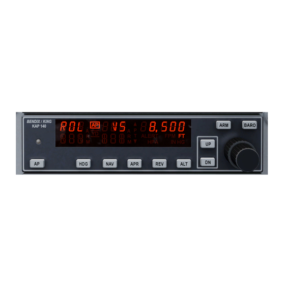
BENDIX/KING KAP 140 2.4.3 TWO--AXIS VERSIONS The following figures shows the two--axis FCCs, with and without altitude preselect capability. The last figure shows all KC 140 display segments. NOTE Lamp is only on --5xx3 and --7xx3 versions and above. FIGURE 2--2 TWO--AXIS FCC (--5XXX VERSIONS) FIGURE 2--3 TWO--AXIS FCC W/ALTITUDE PRESELECT AND ALERTING (--7XXX VERSIONS) FIGURE 2--4 FULL KAP 140 DISPLAY (LAMP TEST) -
Page 30: User Controls
BENDIX/KING KAP 140 2.5 USER CONTROLS 2.5.1 PANEL BUTTONS All flavors of the FCC are functional subsets of the full--featured system FCC. Therefore, the description of functions for the high--end FCC also applies to lower--level systems containing the same feature. The full--featured flavor of the FCC provides the following pushbuttons: Switch Function Couples Autopilot in default modes. -
Page 31: Annunciators
BENDIX/KING KAP 140 2.6 ANNUNCIATORS 2.6.1 MODE ANNUNCIATIONS The FCC provides four alphabetic display fields for mode annunciations. The four fields provide annunciations for the roll coupled mode, roll arm mode, pitch coupled mode, and pitch arm mode. The roll coupled mode annunciations are: ROL, HDG, NAV, APR, and REV. The roll arm mode annunciations are: NAV, APR, and REV (with “ARM”). -
Page 32: Numeric Display
BENDIX/KING KAP 140 2.7 NUMERIC DISPLAY 2.7.1 GENERAL If preselect capability is installed, the numeric window normally displays Selected Altitude in units of “FT”. This window also displays the reference for Vertical Speed mode (if engaged) for 3 seconds after engagement or the last press of the UP or DN buttons or when CWS is pressed. However, the display will default back to displaying selected altitude if the inc/dec knobs are turned. -
Page 33: Alerting
BENDIX/KING KAP 140 2.8 ALERTING The FCC will provide aural and visual alerting for the conditions described below. The aural alerts consist of standard--frequency alerting tones, followed, if enabled, by a voice synthesized message describing the event. The audio alerting circuitry is powered from a separate audio power bus, to provide independence from autopilot power. -
Page 34: Ther Vo I Ce M Essag Es
BENDIX/KING KAP 140 2.8.4 OTHER VOICE MESSAGES In addition to the three voice messages described above, if autotrim is not installed, the FCC shall provide a “check pitch trim” message whenever the autopilot is engaged and pitch mistrim indications have been flashing for ten seconds. On --5403, --5504, --7703 and --7904 versions: If autotrim is installed, the FCC shall provide a “check pitch trim”... -
Page 35: Built--In Test
BENDIX/KING KAP 140 2.9 BUILT--IN TEST The AFCS provides Built--In--Test capabilities to assist service personnel in installing and troubleshooting the system. This capability is accessed via an RS232 port in the cockpit, using a portable PC or dumb terminal. 2.9.1 MANUAL ADJUSTMENTS The FCC contains a single adjustment potentiometer, which is used to make user/installer adjustments. -
Page 36: Operating Modes
BENDIX/KING KAP 140 2.10 OPERATING MODES Normal mode operation will be inhibited until the preflight test has been performed. When the CWS switch is active, the autopilot control will be momentarily released and the pitch mode reference will synchronize to the aircraft if engaged in VS or ALT HOLD modes. 2.10.1 ROLL COUPLED MODES 2.10.1.1 Roll Default Mode (ROL) The ROL mode uses the combined yaw/roll rate gyro sensor to provide a servo command which... - Page 37 BENDIX/KING KAP 140 2.10.1.4 Navigation Coupled Mode (NAV) The NAV coupled mode provides roll commands to capture and track the selected NAV course on the HSI. The preferred intercept is between 30 and 60 degrees, however, the AFCS performs all angle intercepts if course datum is provided.
-
Page 38: L L Arm M O Des
BENDIX/KING KAP 140 2.10.2 ROLL ARM MODES 2.10.2.1 Navigation Arm Mode (NAV ARM) The NAV arm mode determines when to automatically activate the NAV coupled mode. The NAV mode is activated whenever the NAV button is pressed and NAV (arm or coupled) mode is not already active. - Page 39 BENDIX/KING KAP 140 2.10.2.5 Autointercept Mode For DG installations, the FCC provides an automatic 45 degree intercept of the selected navigation course when the system is in HDG mode and NAV ARM or APR ARM or REV ARM is engaged. The system will transition to autointercept mode.
-
Page 40: Pitch Coupled Modes
BENDIX/KING KAP 140 2.10.3 PITCH COUPLED MODES 2.10.3.1 VERTICAL SPEED MODE (VS) The VS mode is the default pitch mode and provides pitch FD commands to hold the reference vertical speed. The vertical speed reference is initialized to the altitude rate current upon mode selection. -
Page 41: Pitch Arm Modes
BENDIX/KING KAP 140 2.10.4 PITCH ARM MODES 2.10.4.1 ALTITUDE ARM MODE (ALT ARM) The Altitude Arm mode determines when Altitude Capture mode should automatically activate, which captures the selected altitude. The flight crew must initiate a maneuver to fly toward the preselected altitude (using the VS mode). -
Page 42: Ri M F Uncti O Ns
BENDIX/KING KAP 140 2. 10. 5 T RI M F UNCTI O NS 2. 10. 5. 1 M ist r im Annunciat ion I f aut ot rim is not inst alled, t he syst em shall indicat e t he need f or m anual pit c h t rim whenever t he r equir ed pit ch ser v o eff or t exceeds t he c er t if ied t hr eshold f or f ive seconds. -
Page 43: Enco Di Ng Alti M Eter I Nputs
BENDIX/KING KAP 140 2.15 ENCODING ALTIMETER INPUTS The FCC uses the encoding altimeter inputs to calibrate data from the pressure sensor, yielding an absolute pressure altitude. The baro--correction term can be input either remotely with an analog voltage from the altimeter or via the inc/dec knobs on the FCC. If remote control is selected, the knobs will not be allowed to change baro correction. - Page 44 BENDIX/KING KAP 140 BLANK PAGE MARKER (NEW) Page 2--22 Revision 2, Dec/2002 CS:15574F02.IDU...
- Page 45 BENDIX/KING KAP 140 SECTION III REMOTE TERMINAL INTERFACE 3.1 GENERAL The FCC provides an RS232 interface for diagnostic and installation capabilities. This interface is required for setting up installation parameters for any new installation and recommended for system troubleshooting. The RS232 interface is provided through a Remote Terminal Interface (RTI) jack located in the cockpit.
- Page 46 BENDIX/KING KAP 140 3.3 NAVIGATING THE REMOTE TERMINAL INTERFACE (RTI) SCREENS The following discussion of RTI screens assumes that a properly configured terminal is connected to the RTI. If the RTI screen cannot be obtained by pressing the ENTER key or CTRL--W (screen refresh), check the terminal connections and that the terminal is configured as described above.
- Page 47 BENDIX/KING KAP 140 3.3.2 DIAGNOSTIC MODE SCREENS Pressing ‘D’ while the Main Menu screen is displayed will bring up a diagnostic mode confirmation m essage on t he t er m inal ( Ref er t o Figur e 3 -- 2) .
-
Page 48: Discrete Input Straps/Valids Screen
BENDIX/KING KAP 140 3.3.3 DISCRETE INPUT STRAPS/VALIDS SCREEN Pressing ‘V’ when the Diagnostics Menu screen is displayed will cause the Discrete Inputs Straps/Valids screen, shown in Figure 3--4, to be displayed. Pressing the ‘ENTER’ key at this point will return the user to the Diagnostics Menu screen. System mode: Diagnostic DISCRETE INPUT STRAPS/VALIDS Description... - Page 49 BENDIX/KING KAP 140 ITEM DESCRIPTION Roll Servo Valid Open/Ground discrete input driven by the roll servo valid discrete output. A ‘YES’ implies the input is grounded and therefore the roll servo is valid. Otherwise, ‘NO’ indicates input is open and roll servo is invalid.
- Page 50 BENDIX/KING KAP 140 ITEM DESCRIPTION GS Valid Differential analog input connected to the GS receiver valid output. A ‘YES’ implies the glideslope valid signal is greater than a 140mV threshold and therefore the receiver is valid. Otherwise, ‘NO’ implies the signal is less than this threshold and the receiver is invalid.NAV Valid Differential analog input connected to the NAV receiver valid output.
-
Page 51: Discrete Input Switches Screen
BENDIX/KING KAP 140 3.3.4 DISCRETE INPUT SWITCHES SCREEN Pressing ‘S’ when the Diagnostics Menu screen is displayed will cause the Discrete Inputs Switches screen, shown in Figure 3--5, to be displayed. Pressing the ‘ENTER’ key at this point will return the user to the Diagnostics Menu screen. System mode: Diagnostic DISCRETE INPUT SWITCHES Description... - Page 52 BENDIX/KING KAP 140 ITEM DESCRIPTION APR Switch Momentary pushbutton on front panel of the FCC used to engage/disengage Approach Arm and Tracking mode. ‘YES’ implies switch is pressed. ‘NO’ implies switch is not pressed. REV Switch Momentary pushbutton on front panel of the FCC used to engage/disengage Reverse Localizer Tracking mode.
- Page 53 BENDIX/KING KAP 140 ITEM DESCRIPTION INC/DEC Outer Knob Rotary switch used to adjust baro setting by 0.1 in Hg / 100 hPa increments or change selected altitude in 1000 ft steps. The value displayed on the diagnostic screen represents the current position of the switch. As the switch is rotated clockwise the value will change according to the sequence 0, 2, 3, 1, 0, 2, 3, 1 and continue to repeat.
-
Page 54: Discrete Input Status Screen
BENDIX/KING KAP 140 3.3.5 DISCRETE INPUT STATUS SCREEN Pressing ‘D’ when the Diagnostics Menu screen is displayed will cause the Discrete Inputs Status screen, shown in Figure 3--6, to be displayed. Pressing the ‘ENTER’ key at this point will return the user to the Diagnostics Menu screen. - Page 55 BENDIX/KING KAP 140 ITEM DESCRIPTION Roll Clutch Engaged Indicates engagement status of roll clutch solenoid based on sensing current flow through the low side solenoid driver in the FCC. The detection threshold is set at 120mA with a hysteresis of 30mA. A ‘YES’ implies solenoid current is greater than the detection threshold and therefore the roll clutched is engaged.
- Page 56 BENDIX/KING KAP 140 ITEM DESCRIPTION ILS Engaged Open/ground discrete input connected to a discrete output of either a VOR/ILS or GPS receiver. For a VOR/ILS receiver, a ‘YES’ implies the input is grounded and the receiver is in ILS mode. A ‘No’ implies the input is open and the receiver is in VOR mode.
- Page 57 BENDIX/KING KAP 140 ITEM DESCRIPTION Pitch Clutch Engaged Indicates engagement status of pitch clutch solenoid based on sensing current flow through the low side solenoid driver in the FCC. The detection threshold is set at 120mA with a hysteresis of 30mA. A ‘YES’ implies solenoid current was greater than the detection threshold and therefore the pitch clutched is engaged.
- Page 58 BENDIX/KING KAP 140 3.3.6 DISCRETE OUTPUTS SCREEN Pressing ‘O’ when the Diagnostics Menu screen is displayed will cause the Discrete Outputs Status screen, shown in Figure 3--7, to be displayed. Pressing the ‘ENTER’ key at this point will return the user to the Diagnostics Menu screen. System mode: Diagnostic SET DISCRETE OUTPUTS --------------------...
- Page 59 BENDIX/KING KAP 140 ITEM DESCRIPTION Audio Volume This output can be set from “0” (minimum volume) to “7” (maximum volume), to adjust the 500 ohm audio output level. NOTE: Audio Volume settings made on this screen will only affect the volume while in diagnostics, except in units with 01/04 SW or earlier.
-
Page 60: Analog Inputs Screen
BENDIX/KING KAP 140 3.3.7 ANALOG INPUTS SCREEN Pressing ‘A’ when the Diagnostics Menu screen is displayed will cause the Analog Inputs screen, similar to Figure 3--13, to be displayed. Pressing ‘ENTER’ when this screen is displayed returns the user to the Diagnostics Menu screen. This screen includes analog inputs from various sensor sources, typically scaled in engineering units. - Page 61 BENDIX/KING KAP 140 ITEM DESCRIPTION Roll Rate Combined roll rate and yaw rate output signal supplied from the turn coordinator with a scale factor of 333 mV per deg/sec. Input range is ± 7.5 deg/s. Displayed resolution is 0.014 deg/s per bit. Validity based on Rate Valid input.
- Page 62 BENDIX/KING KAP 140 ITEM DESCRIPTION Pressure sensor ratio Pressure sensor internal to the FCC. The displayed value is a ratio of sensor output to supply reference. Sensor range is from 0.89500 (--2500 ft) to 0.00000 (+51,800 ft). Note increase altitude corresponds to a decrease in pressure sensor ratio.
-
Page 63: Analog Voltage Inputs Screen
BENDIX/KING KAP 140 3.3.8 ANALOG VOLTAGE INPUTS SCREEN Pressing ‘I’ when the Diagnostics Menu screen is displayed will cause the Analog Inputs screen, similar to Figure 3--9, to be displayed. Pressing ‘ENTER’ when this screen is displayed returns the user to the Diagnostics Menu screen. System mode: Diagnostic ANALOG VOLT INPUTS Description... - Page 64 BENDIX/KING KAP 140 ITEM DESCRIPTION Dim Bus Aircraft lighting power bus input to the FCC to adjust brightness of pushbutton and panel nomenclature. Input range is 0 to 34.5 VDC. Resolution of display value is 34 mV per bit. Validity based on internal Analog Valid.
- Page 65 BENDIX/KING KAP 140 ITEM DESCRIPTION GS Valid Low--level analog validity signal supplied from the VOR/ILS receiver. Amplitude is based on strength of radio signal. The GS deviation signal is considered valid when this output is above 180mV. Input range is ± 402 mV. Resolution of display value is 0.78mV per bit.
- Page 66 BENDIX/KING KAP 140 3.3.9 ANALOG OUTPUTS SCREEN Pressing ‘W’ when the Diagnostics Menu screen is displayed will cause the Set Analog Outputs screen, Figure 3--10, to be displayed. Pressing ‘ENTER’ when this screen is displayed returns the user to the Diagnostics Menu screen. System mode: Diagnostic SET ANALOG VALUES 1 - Roll Servo...
-
Page 67: Analog Tests Screen
BENDIX/KING KAP 140 3.3.10 ANALOG TESTS SCREEN Pressing ‘T’ when the Diagnostics Menu screen is displayed will cause the Analog Tests screen, shown in Figure 3--11, to be displayed. Pressing ‘ENTER’ when this screen is displayed returns the user to the Diagnostics Menu screen. Pressing a key corresponding to a particular test on the Analog Test screen will cause that test to be performed. - Page 68 BENDIX/KING KAP 140 3.3.11 ERROR LOG SCREEN Pressing ‘L’ when the Main Menu screen is displayed will cause the Error Log Menu screen, shown in Figure 3--12, to be displayed. System mode: Normal Error Log --------- D - Display Error Log F - Dump Error Log for file capture C - Clear Error Log R - Reset Error Log...
- Page 69 BENDIX/KING KAP 140 System mode: Normal KC 140 error log Number of errors: 10; Current power cycle and delta time: 6, 01:02:45 Power cycle Delta Time Error Description --- ----------- ---------- ----- ------------------------------ 00:02:03 roll invalid 00:05:09 lat cpld invalid 00:00:07 accel mon below lower lmt 00:00:30...
- Page 70 BENDIX/KING KAP 140 3.3.12 SOFTWARE IDENTIFICATION SCREEN Pressing ‘S’ when the Main Menu screen is displayed will cause the Software Identification screen, similar to Figure 3--14, to be displayed. Pressing ‘ENTER’ when this screen is displayed returns the user to the Main Menu screen. This screen displays the part number of the software installed in the FCC.
- Page 71 BENDIX/KING KAP 140 3.4 INSTALLATION SETUP 3.4.1 INSTALLATION SETUP SCREEN Pressing ‘1’ followed by ‘ENTER’ when the Installation Menu screen is displayed will prompt the user to upload an installation file (i.e. *.CER file), as shown in Figure 3--16. Pressing the ‘ESC’ key at this point will return the user to the Installation Menu screen.
- Page 72 BENDIX/KING KAP 140 The data is received by the FCC and stored in the configuration module. During upload, the FCC verifies the file type is correct and that data transfers without corruption. If the upload was unsuccessful, one of the following messages is displayed and it may be necessary to press the ‘ESC’...
- Page 73 BENDIX/KING KAP 140 3.4.2 INSTALLATION OFFSETS Pressing ‘2’ followed by ‘ENTER’ when the Installation Menu screen is displayed will cause the Installation Offsets screen to be displayed, as shown in Figure 3--17. Pressing the ‘ENTER’ key at this point will return the user to the Installation Menu screen. This screen lists sensor inputs to the FCC whose offsets can be compensated for by software in order to optimize system performance.
- Page 74 BENDIX/KING KAP 140 3.5 OTHER INSTALLATION OPTIONS The following are options that are selected by the installer. Some of these options depend upon aircraft certification and version of FCC and therefore may not be displayed. OPTION DESCRIPTION Audio Volume Volume setting for audio tones and voice messaging. A volume setting of ‘0’...
- Page 75 BENDIX/KING KAP 140 SECTION IV TROUBLESHOOTING 4.1 GENERAL The Rem ot e Ter m inal I nt er f ace is an im por t ant r esour ce f or t r oubleshoot ing pr oblem s involving t he KAP 140 syst em. A descript ion of t he problem as viewed f r om t he c ockpit t oget her wit h t he logged er r or s accessible v ia t he RTI will help t o nar r ow t he f ocus of t r oubleshoot ing.
- Page 76 BENDIX/KING KAP 140 Symptom Possible Cause(s) Checks to Perform Pitch servo slip clutch set be- Check and adjust slip clutch torque to low minimum torque. certified value. Autotrim not working properly. Check for normal autotrim response to induced effort on control wheel. Check trim sense signal in diagnostics for proper response to control effort.
- Page 77 BENDIX/KING KAP 140 4.3 UNIT INTERFACE DESCRIPTIONS 4.3.1 GENERAL Not all KAP 140 Autopilot System configurations have all the interfaces described here. Refer to the appropriate STC manual to determine which interfaces apply to your aircraft. In the following paragraphs certain I/O descriptions are common across different interface descriptions.
- Page 78 BENDIX/KING KAP 140 motor via the internal servo amplifier. The command high input is a +/-- 10V signal (through a 2Kohm series resistor) generated by the KC 140 Flight computer. The command low input is a reference back to an internal KC 140 Flight computer ground. The value of the output signal determines how fast the servo is driven.
- Page 79 BENDIX/KING KAP 140 4.3.3 KS 271C ROLL SERVO INTERFACE TO THE KC 140 DESCRIPTION P1401 -- 1 ROLL_CLUTCH P1401 -- 5 ROLL_SERVO_VALID P1401 -- 18 ROLL_SERVO_CMD_+ P1401 -- 19 ROLL_SERVO_CMD_REF The KS 271C Roll Servo consists of the following interfaces: a clutch high--side and a clutch low--side input, and a command high and a command low input.
- Page 80 BENDIX/KING KAP 140 command of 2V will produce a voltage of 10V across the motor. The servo motor drive is powered by an internal regulator, which limits the maximum voltage that can be applied to the motor. The TRIM FAIL signal from the FCC is connected to the trim servo disable input, which turns off the internal regulator and is used to remove power from the servo motor when the trim monitoring detects a failure.
- Page 81 BENDIX/KING KAP 140 to the directional gyro. They are capable of supplying 30mA of current. The CRS_DATUM input (used for heading datum and course datum) is an analog input that can be viewed through the diagnostic pages. DIAGNOSTIC NAME SCALE FACTOR Course Datum 210 mV/deg 4.3.7 HORIZONTAL SITUATION INDICATOR (HSI) INTERFACE TO THE KC 140...
- Page 82 BENDIX/KING KAP 140 4.3.8 KCM 100 CONFIGURATION MODULE INTERFACE TO THE KC 140 DESCRIPTION P1401 -- 4 CFG_+5V P1401 -- 8 CFG_DATA P1401 -- 13 CFG_ENABLE P1401 -- 30 CFG_CLK The KCM 100 Configuration Module Interface consists of a clock, enable, data, and 5V power. All of these signals are logic level signals (0--5V).
- Page 83 BENDIX/KING KAP 140 4.3.9 NAV SENSOR INTERFACE TO THE KC 140 DESCRIPTION P1401 -- 7 P1401 -- 22 NAV_VALID_+ P1401 -- 23 NAV_VALID_-- P1401 -- 24 NAV_DEV_+ P1401 -- 25 NAV_DEV_-- P1402 -- 9 GS_DEV_+ P1402 -- 10 GS_DEV_-- P1402 -- 12 GS_VALID_-- P1402 -- 26 GPS_SELECT...
- Page 84 BENDIX/KING KAP 140 4.3.10 ENCODING ALTIMETER INTERFACE TO THE KC 140 DESCRIPTION P1402 -- 3 P1402 -- 5 P1402 -- 11 P1402 -- 13 P1402 -- 14 P1402 -- 16 BARO_SET P1402 -- 20 P1402 -- 21 P1402 -- 29 P1402 -- 33 P1402 -- 34 P1402 -- 36...
- Page 85 BENDIX/KING KAP 140 4.3.11 RS232 INTERFACE TO THE KC 140 DESCRIPTION P1401 -- 28 TXD_RS232 P1401 -- 29 RXD_RS232 The RS232 interface consists of two signal lines: RXD_RS232 (receive), and TXD_RS232 (transmit). The KC 140 uses this interface to talk to the personal computer (PC) or laptop computer. This interface allows the KC 140 flight computer to transmit error codes, save installation parameters, and enter the diagnostic pages.
- Page 86 BENDIX/KING KAP 140 4.3.13 COCKPIT SWITCHES INTERFACE TO THE KC 140 DESCRIPTION P1401 -- 9 AP_DISC P1401 -- 26 P1402 -- 22 TRIM_UP P1402 -- 25 TRIM_ARM P1402 -- 27 TRIM_DN P1402 -- 30 STALL_WARNING AP_DISC is a 28V/Open discrete input. AP_DISC is 28V when not pressed and open when pressed.
- Page 87 BENDIX/KING KAP 140 4.3.15 FLAPS INTERFACE TO THE KC 140 DESCRIPTION P1402 -- 45 FLAPS_+ P1402 -- 46 FLAPS_-- The FLAPS input on the KC 140 interfaces to the flaps motor in the aircraft. When the flaps are in motion, the software in the KC 140 begins running trim in the aircraft to help prevent the pitch servo from getting behind during configuration changes.
- Page 88 BENDIX/KING KAP 140 4.3.16 KC 140 ALERTING OUTPUTS DESCRIPTION P1401 -- 20 TONE_ALERT P1402 -- 44 TRIM_FAIL These outputs provide a low--side current sink for the cockpit annunciators. One side of the annunciator is wired to aircraft power and the other side of the annunciator is wired to the KC 140 output pin.
- Page 89 BENDIX/KING KAP 140 4.3.18 KC 140 POWER INPUTS DESCRIPTION P1401 -- 14 AUDIO_POWER P1401 -- 15 CHASSIS_GND P1401 -- 16 AIRCRAFT_POWER P1401 -- 35 POWER_GND P1402 -- 15 POWER_GND The AUDIO_POWER input is used to provide operating power for the audio alerting circuitry. This circuitry is powered separately from the rest of the KC 140, so that in the event of loss of aircraft power the AP disconnect tone can be generated.
- Page 90 BENDIX/KING KAP 140 4.3.19 KC 140 AIRCRAFT STRAPS DESCRIPTION P1401 -- 17 STRAP_5 P1401 -- 31 STRAP_1 P1401 -- 32 STRAP_2 P1401 -- 33 STRAP_3 P1401 -- 34 STRAP_4 P1401 -- 36 STRAP_6 The above inputs are Open/Ground discrete inputs. For each aircraft certification, the KAP 140 Autopilot System uses a different combination of inputs tied to ground and inputs left open.
- Page 91 BENDIX/KING KAP 140 SECTION V ERROR CODES 5.1 GENERAL INFORMATION This document describes the error codes generated by the KC 140 Flight Control Computer. This information should be used to help in troubleshooting KAP 140 system failures. In addition, the Maintenance Manual Supplement for KAP 140 Automatic Flight Control System can be helpful for diagnostics when troubleshooting.
- Page 92 BENDIX/KING KAP 140 5.3 ERROR CODE CATEGORIES The following lists the general categories in which the KC 140 errors are grouped. It includes a category name, a description of the category, and the range of error code numbers contained in that category.
- Page 93 BENDIX/KING KAP 140 5.4 ERROR CODE DESCRIPTIONS The following lists the error code number, text message, unit(s) where failure may have occurred and a description for each error logged by the KC 140 flight computer. ERR# TEXT MESSAGE(S) POSSIBLE FAILED UNIT(S) DESCRIPTION OF ERROR Exception vector error KC 140...
- Page 94 BENDIX/KING KAP 140 ERR# TEXT MESSAGE(S) POSSIBLE FAILED UNIT(S) DESCRIPTION OF ERROR Timer failed KC 140 The processor failed the timer test on power up. Autopilot operation is disallowed. Watchdog timed out KC 140 The watchdog was not reset in the allowed time period. This indicates a probable hardware fault in the flight computer.
- Page 95 BENDIX/KING KAP 140 ERR# TEXT MESSAGE(S) POSSIBLE FAILED UNIT(S) DESCRIPTION OF ERROR Norm accel below tst lower limit KC 140 Preflight test failed due to improper response of the accelerometer during self test. This indicates a probable failure in the accelerometer or the associated circuitry of the flight computer.
- Page 96 BENDIX/KING KAP 140 ERR# TEXT MESSAGE(S) POSSIBLE FAILED UNIT(S) DESCRIPTION OF ERROR Trim mon 4 -- auto failed KC 140, KS 270C, KS 272C, harness wiring Preflight test failed due to improper response of the runaway/autotrim monitor. The monitor did not detect (i.e. fail) a trim down drive with a valid MET UP condition. This indicates a probable failure in the trim runaway/autotrim monitor of the flight computer.
- Page 97 BENDIX/KING KAP 140 ERR# TEXT MESSAGE(S) POSSIBLE FAILED UNIT(S) DESCRIPTION OF ERROR Trim mon 5 -- MET failed KC 140 Preflight test failed due to improper response of the MET latent switch monitor. The monitor did not detect a DN switch in the absence of an ARM. This indicates a probable failure in the MET monitor of the flight computer.
- Page 98 BENDIX/KING KAP 140 ERR# TEXT MESSAGE(S) POSSIBLE FAILED UNIT(S) DESCRIPTION OF ERROR Acc mon failed clutch interrupt KC 140, KS 270C, KS 271C, KS 272C, harness wiring The accelerometer monitor did not disengage the pitch, roll, or trim clutch during PFT. Probable fault in clutch engagement logic. This error code is not present in software flavors --0105, --0106, and --0201.
- Page 99 BENDIX/KING KAP 140 ERR# TEXT MESSAGE(S) POSSIBLE FAILED UNIT(S) DESCRIPTION OF ERROR Lat cpld illegal xsit mode KC 140 An error has occurred in the mode logic. GS tracked w/ GS track req KC 140 An error has occurred in the mode logic. GS tracked w/ alt capture req KC 140 An error has occurred in the mode logic.
- Page 100 BENDIX/KING KAP 140 ERR# TEXT MESSAGE(S) POSSIBLE FAILED UNIT(S) DESCRIPTION OF ERROR Lat cpld invalid KC 140, Nav Sensor, Hdg Sensor, Turn & Bank Indicator, harness wiring The roll coupled mode has been deactivated due to invalid inputs that prevent proper algorithm calculation.
- Page 101 BENDIX/KING KAP 140 ERR# TEXT MESSAGE(S) POSSIBLE FAILED UNIT(S) DESCRIPTION OF ERROR Pitch invalid KC 140, KS 270C, harness wiring The pitch autopilot has been deactivated due to invalid inputs that prevent proper algorithm calculation. The default pitch attitude hold mode will be dumped if the KS 270C pitch valid signal is invalid for 1 second or the KC 140 Accel valid signal is invalid for 1 second without CWS being pressed or the KC 140 Accel reasonability monitor has detected an unreasonable Accel output.
- Page 102 BENDIX/KING KAP 140 ERR# TEXT MESSAGE(S) POSSIBLE FAILED UNIT(S) DESCRIPTION OF ERROR Autotrim runaway KC 140, KS 272C, KS 270C, harness wiring The trim servo was detected in opposition to the primary servo command. This may indicate an autotrim failure. The Autotrim operation of the AP mode and Manual Electric Trim operation will be disallowed until AP power is cycled and the KC 140 successfully passes pre--flight test.
- Page 103 BENDIX/KING KAP 140 ERR# TEXT MESSAGE(S) POSSIBLE FAILED UNIT(S) DESCRIPTION OF ERROR ECAL Bad sign input to summer KC 140 An error has occurred in the mode algorithm calculation. ECAL Not enough node inputs KC 140 An error has occurred in the mode algorithm calculation. ECAL Filtering out of range KC 140 An error has occurred in the mode algorithm calculation.
- Page 104 BENDIX/KING KAP 140 ERR# TEXT MESSAGE(S) POSSIBLE FAILED UNIT(S) DESCRIPTION OF ERROR Error in Encoding Altimeter Input Altimeter, KC140 The parallel altitude information from the altimeter is not a valid Gilham code. The altimeter may be powered off or there may be a broken wire in the harness.
- Page 105 BENDIX/KING KAP 140 ERR# TEXT MESSAGE(S) POSSIBLE FAILED UNIT(S) DESCRIPTION OF ERROR Acc Mon trim clutch eng failed KC 140, KS 272C, harness wiring An attempt to engage the trim clutch during PFT failed. No current was sensed in the trim clutch. This error code is not present in software flavors --0103, and --0104.
- Page 106 BENDIX/KING KAP 140 ERR# TEXT MESSAGE(S) POSSIBLE FAILED UNIT(S) DESCRIPTION OF ERROR Acc HP has long time constant KC 140 Preflight test failed due to the time constant of the high passed acceleration being too long in the flight computer. This error code is not present in software flavors --0103, --0104, and --0105.
- Page 107 THE END...
- Page 108 BLANK PAGE MARKER (NEW)
Need help?
Do you have a question about the BENDIX/KING KAP 140 and is the answer not in the manual?
Questions and answers