Honeywell EXPERION PKS Installation Manual
Controlnet
Hide thumbs
Also See for EXPERION PKS:
- User manual (270 pages) ,
- Specifications and technical data (47 pages)

Related Manuals for Honeywell EXPERION PKS


Summary of Contents for Honeywell EXPERION PKS
- Page 1 XPERION ELEASE ControlNet Installation Guide EPDOC-XX25-en-515A November 2019...
- Page 2 Honeywell International Sàrl. While this information is presented in good faith and believed to be accurate, Honeywell disclaims the implied warranties of merchantability and fitness for a purpose and makes no express warranties except as may be stated in its written agreement with and for its customer.
-
Page 3: Table Of Contents
Contents Chapter 1 - About This Document 1.1 Revision History Chapter 2 - System Cabling and Wiring Installation 2.1 Experion system cabling and wiring 2.1.1 LAN (TCP/IP - Ethernet) 2.1.2 ControlNet Network 2.1.3 Field Wiring 2.1.4 Power and ground 2.2 Before You Begin 2.2.1 Planning 2.2.2 Obtain Documentation 2.2.3 General Installation Checklist... - Page 4 4.3.1 Mounting dimensions for repeaters 4.3.2 Mounting your repeater 4.3.3 Grounding your repeater 4.3.4 Connecting ControlNet cables to your repeater 4.3.5 Connecting power and relay circuitry Chapter 5 - Building ControlNet Trunk Cables 5.1 Preparing to Build ControlNet Trunk Cabling 5.1.1 Materials needed 5.1.2 Tools needed 5.1.3 Bulk cable testing...
- Page 5 7.3.3 Connecting ControlNet devices 7.3.4 Connecting to repeaters 7.3.5 Connecting to ControlNet Interface modules 7.3.6 Connecting to the Server ControlNet Interface module for the PC 7.3.7 Connecting Tap Dummy Loads Chapter 8 - Appendix A 8.1 CSA Hazardous Location Approval 8.1.1 CSA Certification 8.1.2 Temperature Ratings 8.1.3 Notices...
-
Page 6: Chapter 1 - About This Document
CHAPTER BOUT OCUMENT This document provides guidelines and procedures for installing ControlNet network components and making and testing ControlNet cables. Revision History Revision Date Description November 2019 Initial release of the document. - 6 -... -
Page 7: Chapter 2 - System Cabling And Wiring Installation
CHAPTER YSTEM ABLING AND IRING NSTALLATION Experion system cabling and wiring Before You Begin Experion system cabling and wiring Your Experion system's cable and wiring requirements can be broken down into four basic categories: Ethernet Plant Information Network (PIN), Supervisory ControlNet Network, I/O ControlNet Network, and Field Wiring, as illustrated in Figure1. -
Page 8: Lan (Tcp/Ip - Ethernet)
Chapter 2 - System Cabling and Wiring Installation Power and ground 2.1.1 LAN (TCP/IP - Ethernet) Your Experion system uses a local area network (LAN, see figure) for server-to-station and station-to- server communications. This network may also provide links to other higher order networks and communication systems. -
Page 9: Before You Begin
Before installing any Experion cabling or wiring, obtain all available and pertinent documentation. This should include all documentation supplied by Honeywell, your site's engineering documentation, and that from any additional third party suppliers whose products are involved in this installation. -
Page 10: Chapter 3 - Controlnet Pcic Card Installation
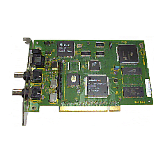
CHAPTER PCIC C ONTROL NSTALLATION About the ControlNet PCIC Card Installing the PCIC Card About the ControlNet PCIC Card The Peripheral Component Interconnect communication (PCIC) interface card lets a PCI Local bus compatible computer communicate directly with other ControlNet products. Figure 3.1 Front View - 10 -... -
Page 11: Compliance To European Union Directives
Chapter 3 - ControlNet PCIC Card Installation Figure 3.2 Component Side View Compliance to European Union Directives Component handling guidelines About PCIC card drivers 3.1.1 Compliance to European Union Directives This product has the CE mark (on its packaging) and is approved for installation within the European Union and EEA regions. -
Page 12: Component Handling Guidelines
Chapter 3 - ControlNet PCIC Card Installation 3.1.2 Component handling guidelines The PCIC card uses CMOS technology, NOTE which is highly sensitive to electrostatic Electrostatic discharge discharge (ESD). ESD may be present whenever you are handling the card. Handling a card without any ESD protection can cause internal circuit damage that may not be apparent during installation or initial use. -
Page 13: Accessing The Expansion Slots
Chapter 3 - ControlNet PCIC Card Installation Be sure you know how to install hardware in your computer. And, have the computer's documentation available for reference. Be sure you have installed the operating system for your computer and configured your options. Be sure you are wearing a grounding wrist strap before you handle the card. -
Page 14: Chapter 4 - Controlnet Network Component Installation
CHAPTER ONTROL ETWORK OMPONENT NSTALLATION Preparing to Install ControlNet Components About Mounting Taps Installing Repeaters Preparing to Install ControlNet Components 4.1.1 Prepare for installation Before you begin to install your ControlNet networks, please review Control Hardware Planning Guide to ensure that all pre-installation planning and activities have been considered. 4.1.2 Components For a listing of the components associated with the ControlNet network, refer to the Control Hardware... -
Page 15: Esd/Emi Immunity
Chapter 4 - ControlNet Network Component Installation Planning for Your Taps Planning Your Nodes Planning for Terminators Planning Your ControlNet Addressing 4.1.5 ESD/EMI Immunity For more information concerning ESD/EMI Immunity planning, guidelines, and practices, refer to: Planning for Static Electricity Minimization Planning for Interference Minimization Planning Raceway Layouts Planning for Bonding and Grounding... - Page 16 Chapter 4 - ControlNet Network Component Installation Y-tap Universal Mounting Bracket - 16 -...
-
Page 17: Mounting Taps
Chapter 4 - ControlNet Network Component Installation 4.2.2 Mounting taps You can mount your ControlNet taps (Y-tap and T-tap): to a universal mounting bracket (included with the tap), and then mount the tap and bracket as an assembly through the body holes in the tap using: screws and flat washers a tie wrap ATTENTION... - Page 18 Chapter 4 - ControlNet Network Component Installation 4. Mount the tap and bracket (if used) to a suitable fixture using the appropriate method. DIN Rail Mounting Flat Surface Mounting - 18 -...
-
Page 19: Identifying Drop-Cables
Chapter 4 - ControlNet Network Component Installation Through Body Hole Mounting CAUTION Do not over-tighten the screws. Doing so can damage the tap. Applied torque should be 0.2-0.4 N•M (1-2 ft-lbs.). 4.2.3 Identifying drop-cables ATTENTION If you have not already done so, this is a good time to apply identification to your drop-cables. For more information regarding drop-cable identification, refer to the Planning Guide, ControlNet Configuration, Planning Your Taps, Planning for drop-cable identification Identifying the drop-cables from the taps you install makes locating system parts and troubleshooting... -
Page 20: Installing Repeaters
Chapter 4 - ControlNet Network Component Installation To identify the drop-cables 1. After installing your tap, locate the drop-cable identifying labels in your tap kit. 2. Apply labels as follows: Apply one red A label at the Supervisory ControlNet (A) drop cable connector. Apply one yellow B label at the Supervisory ControlNet (B) drop cable connector. -
Page 21: Mounting Your Repeater
Chapter 4 - ControlNet Network Component Installation 4.3.2 Mounting your repeater Mount your repeaters following the: Specifications set forth in your site documentation, Rules defined for repeater installation (see Installing Repeaters, Rules in this section), and Mounting dimensions for repeaters provided. -
Page 22: Connecting Controlnet Cables To Your Repeater
Chapter 4 - ControlNet Network Component Installation Figure 4.2 Grounding repeaters 4.3.4 Connecting ControlNet cables to your repeater For information concerning connecting ControlNet cables to your repeater(s), refer to Connecting to repeaters in this guide. 4.3.5 Connecting power and relay circuitry CAUTION If you are using DC to power the repeater, L1 is positive (+) and L2/N is negative (-). - Page 23 Chapter 4 - ControlNet Network Component Installation 2. Connect power to the repeater. 3. If you are: using the fault-relay terminals, go to Step 4 not using the fault-relay terminals, go to Step 5 - 23 -...
- Page 24 Chapter 4 - ControlNet Network Component Installation 4. Connect your relay circuitry to the fault-relay terminals. 5. Replace the terminal strip cover. - 24 -...
-
Page 25: Chapter 5 - Building Controlnet Trunk Cables
In order to build your own ControlNet trunk cables you will need ControlNet-certified trunk cable and connectors, cable stripping and connector crimping tools, and test equipment to test the cables after assembly. Honeywell provides the following to aid you in the construction of your own cables. ControlNet-certified trunk cable ABREPLACE/,(TC-KCC900),/ABREPLACE available on a reel in 275 meter (900 feet) lengths. -
Page 26: Bulk Cable Testing
5.1.3 Bulk cable testing If you have ordered raw bulk ControlNet trunk cable TC-KCC900 from Honeywell, or ControlNet- certified trunk cable from some other source, you may want to test it for structural return loss prior to beginning to build your trunk sections. - Page 27 Chapter 5 - Building ControlNet Trunk Cables The cut adjustments described in the following procedure must be precise. Adjustments as small as 1/12 to 1/8 of a turn can make the difference between a perfect and an imperfect cut. Do not over-tighten the screws of the cable strip tool. The blades should not bend, shift, or penetrate the calibration tool.
-
Page 28: Reversing And Replacing The Cutting Blades
Chapter 5 - Building ControlNet Trunk Cables 5.1.5 Reversing and replacing the cutting blades 1. Use a screwdriver to lift the memory-blade holder and swing it back. 2. Slide the memory-blade cartridge out of the strip tool. - 28 -... - Page 29 Chapter 5 - Building ControlNet Trunk Cables 3. If you are: reversing the memory-blade cartridge to use its second set of blades, go to Step 4. replacing the memory-blade cartridge, go to Step 5. 4. Flip the memory-blade cartridge, and slide it back into the strip tool. Skip Step 5, and go to Step 6. 5.
-
Page 30: Changing The Memory-Blade Holder
Chapter 5 - Building ControlNet Trunk Cables 5.1.6 Changing the memory-blade holder You received two memory-blade holders with your cable strip tool; one is for standard PVC-CL2 cable, and the other is for plenum FEP-CL2P cable. You need to install the appropriate memory-blade holder for the types of cable you are stripping (PVC or FEP). -
Page 31: About Installing Cable Connectors
Chapter 5 - Building ControlNet Trunk Cables About Installing cable connectors Stripping the cable Testing stripped cable for electrical shorts and continuity Attaching connectors to the cable Testing finished cables 5.2.1 Stripping the cable CAUTION When cutting cable sections, make them long enough to route from one tap to the next with sufficient slack so that the bend radius does not exceed the defined requirements. - Page 32 Chapter 5 - Building ControlNet Trunk Cables 2. Insert the cable into the cable strip tool's cutting chamber so that extra cable, approximately 25.4 mm (1 in), extends beyond the edge of the tool. The cutting chamber houses the center conductor that will be exposed when the cable is stripped.
- Page 33 Chapter 5 - Building ControlNet Trunk Cables 4. Holding the cable in one hand, place the index finger of your other hand inside the chamber-gauge ring. Turn the strip tool 360° around the cable. Make four or five full rotations until the strip tool glides easily around the cable.
- Page 34 Chapter 5 - Building ControlNet Trunk Cables 7. Using only your hands (without using the strip tool ) strip away the appropriate portions/layers of the cable. 8. Examine the resulting cuts. The various layers, as illustrated below, should now be exposed. If you do not see the three distinct layers of cable, snip off the end with wire cutters, and repeat the entire cable-stripping process.
- Page 35 Chapter 5 - Building ControlNet Trunk Cables 11. Make sure the center conductor is 4.0 mm (0.157 in.) in length and clean/free of any insulation residue. For PVC cable, use the imprint guide on the back of the ControlNet tap or the strip gauge to verify this.
-
Page 36: Testing Stripped Cable For Electrical Shorts And Continuity
Chapter 5 - Building ControlNet Trunk Cables CAUTION Inspect the stripped cable, checking for any braid stranding that may not have been cut at the proper length. Even one strand coming in contact with the center conductor could short out the cable. If any such strands are found, cut them to the correct length. 5.2.2 Testing stripped cable for electrical shorts and continuity ATTENTION... -
Page 37: Attaching Connectors To The Cable
Chapter 5 - Building ControlNet Trunk Cables If the resistance reading indicates: there is no short , go to Step 2. that a short exists , inspect the ends of the cable for short circuits. If you are unable to locate a short, replace the trunk-cable section. - Page 38 Chapter 5 - Building ControlNet Trunk Cables 1. Slip the crimp ferrule onto the cable. Push it back to the sheath area to keep it out of the way for the moment. 2. Place the center pin over the center conductor. Make sure that the center pin slips completely onto the center conductor.
- Page 39 Chapter 5 - Building ControlNet Trunk Cables 6. Slide the crimp ferrule over the three outer shields and connector base, until the ferrule meets the shoulder on the connector. 7. To crimp the ferrule, position the crimp tool on the ferrule, as close as possible to the connector base and ferrule meeting line.
-
Page 40: Testing Finished Cables
Chapter 5 - Building ControlNet Trunk Cables 5.2.4 Testing finished cables CAUTION Always test your finished trunk cable segments before connecting them to a new or established ControlNet network. For finished cable testing, refer to this section, Testing ControlNet Trunk Cables : Preparing to Test ControlNet Trunk Cables,... -
Page 41: Chapter 6 - Testing Controlnet Trunk Cables
CHAPTER ESTING ONTROL RUNK ABLES Preparing to Test ControlNet Trunk Cables Testing using an Ohmmeter Testing using a Time Domain Reflectometer (TDR) Preparing to Test ControlNet Trunk Cables 6.1.1 Before you begin Two tests are covered here: Testing using an Ohmmeter , and Testing using a Time Domain Reflectometer (TDR). - Page 42 Chapter 6 - Testing ControlNet Trunk Cables If the resistance reading indicates: there is no short , continue with Step 3. that a short exists , use your wire cutters to cut off the connector, install a new connector, and begin testing again.
-
Page 43: Testing Using A Time Domain Reflectometer (Tdr)
Chapter 6 - Testing ControlNet Trunk Cables Testing using a Time Domain Reflectometer (TDR) A Time Domain Reflectometer (TDR) is required to perform these tests. Two potential TDRs for use with these procedures are the: Tektronics 1502, which has a range of 0 to 2000 feet with a 6 in resolution. Tektronics 1503, which has a range of 0 to 50,000 ft with a 3 ft resolution Setup your TDR cable tester as indicated in the following table. -
Page 44: To Test Each Length Of Cable
Chapter 6 - Testing ControlNet Trunk Cables Do NOT connect together and attempt to test multiple lengths of ControlNet trunk cable. Doing so will invalidate the test and will not ensure accurate results. Both ends of every ControlNet trunk cable section must be tested. Keep the TDR batteries (if used) fully charged. - Page 45 Chapter 6 - Testing ControlNet Trunk Cables If your settings are: 15 m (50 ft) example X10 & .5ft/Div 0 dB & 0 dB Loss No Terminator 3. Using both the Zero Ref and Distance controls, position the second pulse with its peak on the vertical center line of the TDR's screen.
- Page 46 Chapter 6 - Testing ControlNet Trunk Cables If your settings are: 15 m (50 ft) example X10 & .5ft/Div 0 dB & 5 dB Loss No Terminator 6. Connect the selected terminator to the free end of the cable under test. Your screen should appear as shown in either the following figures.
- Page 47 Chapter 6 - Testing ControlNet Trunk Cables If your settings are: 15 m (50 ft) example X10 & .5ft/Div 0 dB & 5 dB Loss Terminator connected 7. Observe the Return Loss (dB) settings, add 34 dB of gain to this value and then adjust the Return Loss (dB) control to this new calculated setting.
- Page 48 Chapter 6 - Testing ControlNet Trunk Cables 15 m (50 ft) example X10 & .5ft/Div 30 dB & 9 dB Loss Terminator connected 9. If… any part of the return pulse is three (3) or more divisions from the base line (in either direction)… Then…...
- Page 49 Chapter 6 - Testing ControlNet Trunk Cables If… any part of the trace between the transmitted pulse and the returned pulse is three (3) or more divisions from the base line (in either direction)… Then… the section of ControlNet trunk cable is Rejected. If…...
-
Page 50: Chapter 7 - Controlnet Cable Installation
ControlNet drop cables are supplied as part of taps in tap kits and are a fixed one-meter length that can't be changed, so you can't build our own. 7.1.2 Pre-built cables Table 2 lists the pre-built cables available from Honeywell. Table 7.1 Pre-built ControlNet cables Component Type... -
Page 51: Installing Trunk Cable
PVC-CL2 9904-TPYR ATTENTION In addition to the pre-built trunk cables, you may elect to build your own trunk cables. Honeywell provides the following to aid you in the construction of your own cables. ControlNet-certified trunk cable (TC-KCC900), available on a reel in 275 meter (900 feet) lengths. -
Page 52: Wiring Inside Enclosures
Chapter 7 - ControlNet Cable Installation Table 7.2 External coaxes pull-strength and bend radius pull strength shouldn't exceed minimum allowed bend radius 42.75 kg (95 lbs.) 76.2 mm (3.0 in) 61.65 kg (137 lbs.) 69.9 mm (2.75 in) 7.2.2 Wiring inside enclosures When your trunk cable is not being pulled through conduit, follow these specifications. -
Page 53: Terminating Cable Segments
Chapter 7 - ControlNet Cable Installation 7.3.2 Terminating cable segments To eliminate signal reflections from the ends of the ControlNet network trunk segment, you must attach a ControlNet 75 ohm trunk terminator to the first and last taps on the segment. (The terms “first” and “last”... -
Page 54: Connecting Controlnet Devices
Chapter 7 - ControlNet Cable Installation 2. Install a 75 ohm terminator onto the tap's other BNC connector. 3. Repeat Steps 1 and 2 at the other end of the ControlNet segment. 7.3.3 Connecting ControlNet devices After connecting trunk cables to taps and terminating the segments per previous topics in this section, you may now connect ControlNet-compatible devices (chassis-installed interface modules, repeaters, etc.) to the drop-cables. -
Page 55: Connecting To Repeaters
Chapter 7 - ControlNet Cable Installation NOTE To guard against inadvertent ControlNet outage on a redundant media ControlNet network, remove power from the ControlNet node (CNI) before removing the ControlNet cables. This will ensure that the network will not be dropped if one of the redundant ControlNet cables has already been disconnected or broken. - Page 56 Chapter 7 - ControlNet Cable Installation displays and troubleshooting), check the tap drop-cable for a label indicating the attached segment before making your connection. 1. Remove and save the dust cap located on the straight or right-angle connector of the designated tap on the first segment (Segment 1).
-
Page 57: Connecting To Controlnet Interface Modules
Chapter 7 - ControlNet Cable Installation 5. Connect this tap's straight or right-angle connector to the BNC connector on the repeater labeled as 2. 7.3.5 Connecting to ControlNet Interface modules The following procedure describes connecting drop-cables from your ControlNet taps to ControlNet modules in your controller or I/O chassis. -
Page 58: Connecting To The Server Controlnet Interface Module For The Pc
Chapter 7 - ControlNet Cable Installation From tap's drop-cable: A to connector A on the ControlNet module. B to connector B on the ControlNet module. 7.3.6 Connecting to the Server ControlNet Interface module for the The following procedure describes connecting drop-cables from your ControlNet taps to PCIC cards in your Experion server. -
Page 59: Connecting Tap Dummy Loads
Chapter 7 - ControlNet Cable Installation To connect to the Server ControlNet Interface module for the PC 1. If you are implementing: a non-redundant ControlNet media, go to Step 2 a redundant ControlNet media, skip Step 2 and go to Step 3 2. - Page 60 Chapter 7 - ControlNet Cable Installation The following procedure describes connecting a Tap Dummy Load (TDL) to the drop cable of a ControlNet tap. TDL's are used to properly terminate unconnected drop cables (e.g., spares for future expansion, local service connector, etc.). To connect a Tap Dummy Load 1.
-
Page 61: Chapter 8
CHAPTER PPENDIX CSA Hazardous Location Approval CSA Hazardous Location Approval CSA certifies products for general use as well as for use in hazardous locations. Actual CSA certification is indicated by the product label as shown below, and not by statements in any user documentation. -
Page 62: Temperature Ratings
Chapter 8 - Appendix A 8.1.2 Temperature Ratings ATTENTION Due to the modular nature of a programmable control system, the product with the highest temperature rating determines the overall temperature code rating of a programmable control system in a Class I, Division 2 location. The temperature code rating is marked on the product label as shown. - Page 63 Documentation feedback You can find the most up-to-date documents on the Honeywell Process Solutions support website at: http://www.honeywellprocess.com/support If you have comments about Honeywell Process Solutions documentation, send your feedback to: hpsdocs@honeywell.com...
- Page 64 For support, contact your local Honeywell Process Solutions Customer Contact Center (CCC). To find your local CCC visit the website, https://www.honeywellprocess.com/en-US/contact-us/customer- support-contacts/Pages/default.aspx. Training classes Honeywell holds technical training classes that are taught by process control systems experts. For more information about these classes, contact your Honeywell representative, or see http://www.automationcollege.com. - 64 -...
Need help?
Do you have a question about the EXPERION PKS and is the answer not in the manual?
Questions and answers