Table of Contents
Advertisement
Quick Links
Advertisement
Table of Contents

Related Manuals for Dantherm VentR


Summary of Contents for Dantherm VentR
- Page 1 Installation and service manual Vent R/C 2/4/6 English Version 2.5 - 971763...
- Page 2 Installation and service manual Version 2.5...
-
Page 3: Table Of Contents
Installation and service manual Version 2.5 NDEX 1. G ......................11 ENERAL DESCRIPTION 1.1 U ....................13 NIT CONSTRUCTION 2. T ..........................22 RANSPORT 3. I ........................30 NSTALLATION 3.1 G ........................ 30 ENERAL 3.2 M C/R 6 ..................31 OVING IN 3.3 M R 4.................... -
Page 4: Unit Construction
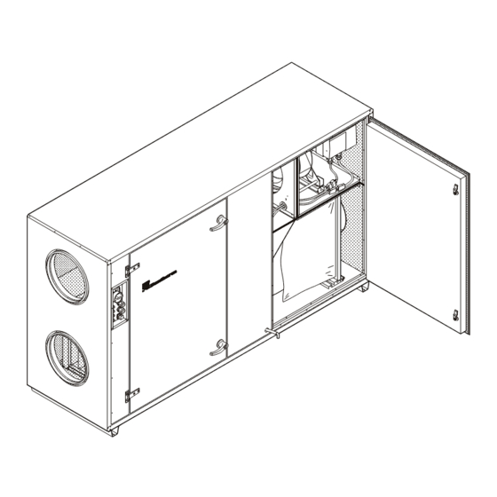
Version 2.5 General Dantherm heat recovery units type VentR/C are complete ventilation units with frequency-controlled rotary heat exchanger or cross flow heat exchanger with by-pass, frequency-controlled plug fans, supply air filters and exhaust air filters as well as a complete, integral electronic control. - Page 5 Installation and service manual Version 2.5 Vent C 6 (pos. left) Fresh air filter F7 Exhaust filter F5 Supply air fan Exhaust fan Elec. panel and STXC2 print Crossflow heat exchanger By Pass Drip tray with outlet...
-
Page 6: Transport
Installation and service manual Version 2.5 Transport All Vent units are supplied as complete units. On request, the biggest models Vent R/C 6 can be separated into three parts, allowing easy transport into plant rooms with limited access. On delivery the unit is placed in upright position on two crossbeams, allowing the use of a forklift truck, a pallet lifter or a crane for lifting and transporting the unit. -
Page 7: Installation
Installation and service manual Version 2.5 Installation of the unit General To avoid vibrations being transmitted to other objects in the room, the unit should be placed on a hard, level and stable surface. Make sure that there is a free access to the inspection doors and that they can be fully opened. Moving in Vent C/R 6 units The Vent R/C 6 is delivered as ready-mounted units. -
Page 8: Moving In Ventr 4
Moving in Vent R 4 units If the overall dimensions of VentR 4 are too big to allow transport through the door opening, the cover panels in front of and behind the rotary heat exchanger can be temporarily dismounted thus reducing the overall width of the unit to less than 890 mm. -
Page 9: Duct Connection
Installation and service manual Version 2.5 Duct connection The duct connections are marked with descriptions of the four airflows for easy and unproblematic connection. Circular duct connections are supplied with rubber sealing gaskets, allowing connection of a duct direct on the connecting piece of the unit. -
Page 10: Fitting Of Accessories
Installation and service manual Version 2.5 Fitting of accessories The Vent unit can be supplied with various accessories. The accessories (except for the supply air sensor) are delivered together with the unit, but separately packed. 3.7.1 Supply air sensor The supply air sensor (black) is ready-mounted in the unit when delivered from the factory. The sensor is led out of the unit next to the main switch. - Page 11 Installation and service manual Version 2.5 3.7.3 LPHW reheat coil If a reheat coil is delivered with the unit, the connecting dimensions of the reheat coil are the same as the connecting dimensions of the Vent unit. Thus the reheat coil can be connected direct on the supply air duct. For transport reasons the frost thermostat with connection box (1) is not fitted from the factory.
-
Page 12: Multi-Leaf Damper
Installation and service manual Version 2.5 3.7.4 Multi-leaf damper If a multi-leaf damper is delivered with the unit, the connecting dimensions of the multi-leaf damper are the same as the connecting dimensions of the Vent unit and therefore the damper can be connected direct on supply and exhaust air ducts, respectively. -
Page 13: Electrical Connection
The mains connection can be 1N~ PE 230V or 2N~ PE 400V. The standard ventilation unit from the factory has a mains power supply of 2N~ PE 400V. Maximum consumption in a VentR ventilation unit 1N~ PE 230V 2N~ PE 400V... -
Page 14: Analogue Cooling Signal
The electrical connection of accessory control current is done directly on the STXC2 print in the Vent unit (except for the reheating coils, which are connected by plug). In the VentR 2/4/6 and VentC 6 the STXC2 print is located behind the control panel, and in the VentC 2/4 under the exhaust filter (see Section 1.1). - Page 15 Electrical connection of accessories In the VentR 2/4/6 and VentC 6 the STXC2 print is located behind the control panel, and in VentC 2/4 under the exhaust filter. From the factory the DIP-switch on the STXC2 control print inside the unit has the...
- Page 16 Installation and service manual Version 2.5 Start-up The unit can be started when all installations and connections have been made. Close all inspection doors and start the unit on the main switch (1). Then choose operational mode on the functional switch (2). ”0”...
- Page 17 Installation and service manual Version 2.5 Factory settings By pressing the Man, Auto and Enter buttons at the same time and holding for 10 seconds the factory default settings for the control system are reverted to. Default values for the ventilation units are as follows: Monday 12:21 Factory menu Air volume K_value...
- Page 18 Installation and service manual Version 2.5 Configuration settings. By pressing the keys Man and Auto at the same time and holding for 5 seconds the configuration settings for the control system are selected. Monday 12:21 Configuration menu Exhaust volume Humidity sensor Auto filter surv.
- Page 19 Installation and service manual Version 2.5 Important! After changing a parameter, press Enter to save the new value. Running condition The actual running condition can at any time be read in the MMI STCU. From the main menu the sub menu Technical data is selected.
- Page 20 Installation and service manual Version 2.5 Service and maintenance The Vent unit must be stopped on the breaker contact on the control panel and then on the main/service switch on the Vent unit itself before carrying out any service. Do not open the inspection doors before the fans have stopped completely! In general service has to be carried out at following intervals: Component...
- Page 21 Installation and service manual Version 2.5 Rotary heat exchanger on Vent R units The rotary heat exchanger must be checked for dirt and damage every 6 month. The rotary heat exchanger is cleaned as follows: Remove fresh air and exhaust air filter (please see section 6.1) ...
- Page 22 Installation and service manual Version 2.5 Fans Check the fans for dirt at least once every 12 months. The fans are cleaned as follows: Vacuum-clean the fan wheels if they are only a little dirty. Wash the fan wheels in soapy water if they are very dirty. If necessary, demount fans and motor in advance.
- Page 23 Installation and service manual Version 2.5 Finding errors on frequency inverter for heat wheel Finding errors with help from indications on the display on the frequency inverter for the heat wheel. The display will show an error as a numeric code like “ERR.XX”. A warning will be shown in the display until the error has been corrected, while an alarm will be shown blinking until [STOP/RESET] has been activated.
- Page 24 Installation and service manual Version 2.5 Indicator lights and fault signal output Two indicator lights and a fault signal output are placed in the terminal box. The function of the indicator lights and the fault signal output is shown in the following table. Furthermore, the fault signal output will signal possible faults.
- Page 25 Installation and service manual Version 2.5 Commissioning diagram Unit type: Vent……………….………. Serial number ……………………………. Adjusted by: ………………………… Company:………………………………..Name ……………………………………. Date: …………………………………….. Function Factory setting Set point Exhaust volume 1. Basic settings of control system Humidity sensor (Push MAN + AUTO buttons simultaneously for 5 sec.) Auto filter surv.
- Page 26 Installation and service manual Version 2.5 Program step 1 -18 Program step No. Ventilation m3/h Day (E) Time Temp. Set point C Night cooling Program step No. Ventilation m3/h Day (E) Time Temp. Set point C Night cooling Program step No. Ventilation m3/h Day (E) Time...
- Page 27 Installation and service manual Version 2.5...
- Page 28 Installation and service manual Version 2.5...
Need help?
Do you have a question about the VentR and is the answer not in the manual?
Questions and answers