Dantherm HCC 260 P1 Service Manual
Hide thumbs
Also See for HCC 260 P1:
- Operating and service instructions (56 pages) ,
- Operating and service instructions (412 pages)
Table of Contents
Advertisement
Advertisement
Table of Contents

Related Manuals for Dantherm HCC 260 P1


Summary of Contents for Dantherm HCC 260 P1
- Page 1 SERVICE MANUAL HCC 260 P1 - HCC 360 P2 - HCC 360 E1 en • Rev. 1.0 • 2020-45-3...
-
Page 2: Table Of Contents
Introduction: Table of contents Introduction Table of contents Table of contents This service manual covers the following main topics: Introduction . . . . . . . . . . . . . . . . . . . . . . . . . . . . . . . . . . . . . . . . . . . . . . . . . . . . . . . . . . . . . . . . . . . . .3 Table of contents . -
Page 3: Overview
Copying of this service manual, or part of it, is forbidden without prior written permission Caution from Dantherm Dantherm reserves the right to make changes and improvements to the product and the Reservations service manual at any time without prior notice or obligation. -
Page 4: Declaration Of Conformity
Introduction: Declaration of conformity Declaration of conformity Declaration of Dantherm hereby, declare that the unit mentioned below: Conformity No.: 352444 Type: HCC 260/360 - complies with the following directives: 2014/35/EU Low Voltage Directive 2014/30/EU EMC Directive 2014/53/EU 2009/125/EC Eco Design Directive (incl. Regulation 2014/1253) -
Page 5: Product Description
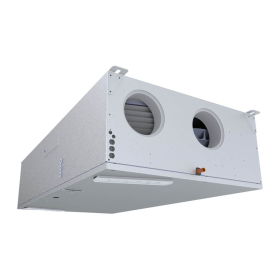
Product description: Overall description Product description Overall description Introduction HCC 260/360 residential ventilation unit is designed to supply fresh air to residential home, by exchanging heat from outgoing air to incoming air, resulting in low heat energy loss. These units are designed for installation underneath a ceiling, in dry surroundings, with tem- peratures >12°C. - Page 6 Product description: Overall description HCC 260/360 There are three different variants of the HCC 260/360 unit: P1, P2, E1. The function and instal- variants lation of the unit is exactly the same. P1, P2, E1 The variants only differ by either heat exchanger or ventilator thus influencing the perfor- mance of the unit.
- Page 7 Product description: Overall description Sensor placement This illustration shows correct placement of sensors (if available) are placed inside the unit. See also “Part description” on page 6 Mode A Mode B Sensor 3 Sensor 1 RH% / VOC RH% / VOC Sensor 2 Sensor 4 Fig.
-
Page 8: Components Description
Humidity sensor The HCC 260 P1 unit, is not default fitted with a RH sensor. RH sensor is available as an acces- sory. HCC 360 P2 and E1 units are fitted with an RH sensor in the extract duct. -
Page 9: Accessory
The preheater is an external enclosure, connected and controlled by the HCC 260/360 con- troller. Hand held Remote For controlling HCC 260/360 control units, Dantherm recommends us- AUTO ing remote control, designed for this range of units. °... -
Page 10: System Operation Strategy
Product description: System operation strategy System operation strategy Introduction This section describes the operation strategy in various conditions. For a user specific running operation see page 26. In cold conditions where T1 is below -4°C and exhaust T4 is <+8°C the condensed water could Defrost built up as ice in the heat exchanger, blocking the air path and eventually destroying the heat exchanger. -
Page 11: Installation
Installation : General location requirements Installation General location requirements Introduction The HCC 260/360 must fulfil all of the previous consideration prior to starting any installation process. Location and duct The following should be considered selecting an appropriate location for installation: connections 1. - Page 12 Installation : General location requirements and here shown in operation mode B 1122 Fig. 10 Description This space is mandatory in order to lift the unit upwards in its wall bracket. Please AL- WAYS mount the bracket and reserve this space, at the unit end, in which the T1 and T4 (cold ducts) are connected.
-
Page 13: Installation Options
Installation : Installation options Installation options Introduction HCC 260/360 has a variety of installation options such as vertical or horizontal mounting, flexible cable routing and duct connections making the unit adaptable to different locations. Check the installation options and decide how the installation best fulfils the local demands. Vertical or horizontal The drain hose must not be down in the floor drain... - Page 14 Installation : Installation options Selecting The air ducts going into the house can either be connected on the right hand side or the left mode A or B hand side. The default mode is mode A. (Follow procedure on page 16 for swapping to mode B) Illustration of duct connections in operation mode A: Fig.
- Page 15 Installation : Installation options Warning Always disconnect the power by removing the 230V plug from the socket, before opening WARNING the unit ! Caution Swapping to If local systems demand mode B, follow the below procedure AND check the label in order to mode B connect the water drainage correctly.
-
Page 16: Mounting
Installation : Mounting Mounting Multi purpose The enclosed bracket can and should be used, both for wall and for ceiling installation. The mounting bracket bracket will automatically tilt the unit 1° towards the condensate drain, when mounted un- derneath the ceiling (fig. 16) and when maounted on the wall (fig. 17). Fig. - Page 17 Installation : Mounting Under ceiling Please follow this below procedure for ceiling installation installation Step Action Illustration The HCC 260/360 should always tilt minimum 1° towards the drain side(T4). This is achieved when us- ing the enclosed bracket, 320 mm placed at T4 end of unit.
- Page 18 Installation : Mounting Connect duct Connect ducts (specification according local regulations), with spigot connection only. system WARNING: NEVER screw any spigot for ducts, directly onto the sheet metal of the unit. Fig. 18 Insulate the ducts according local requirements, taking the installation surrounding tempera- ture into consideration.
- Page 19 Installation : Mounting Drainage It is mandatory in any HCC 260/360 installation to connect a water drain hose to the unit, consideration because the humidity from the extract air condensates to water drops when cooled in the heat exchanger. This water is harmful to its surrounding if not managed correctly. The installation thus needs a condensate water drain hose connected with a decline of minimum 10 Promille (1 cm/meter) away from the unit and the hose must NEVER exceed the level of the lower sheet metal plate.
-
Page 20: Connecting Additional Equipment
Installation : Connecting additional equipment Connecting additional equipment Connecting additional equipment is to be carried out by qualified personnel only. Always Warning WARNING disconnect the power by removing the 230V plug from the socket, before opening the unit ! Caution Access to The integrated controller has various options to connect additional external equipment. - Page 21 MODBUS MODBUS: MODBUS RTU is only for internal communication between unit (UVC print) and Dantherm accessories (HAC, FPC, or HCP11) Connected via RS485 port Important! External BMS can not be connected as a Modbus RTU via RS485 port, nor via Dantherm accesso-ries .
- Page 22 Installation : Connecting additional equipment Dig . input The unit is fitted with 2 overrule inputs, also called digital inputs. These inputs can be used for selecting other fan speed level or activating alarms. As default the digital input are setup to: •...
-
Page 23: Initial Calibration
Installation : Initial calibration Initial calibration Introduction After the installation the unit need to be calibrated to adapt any specific duct system. This is done by connecting a computer with MS Windows, to the USB hidden under a black rubber ceiling, on the front cover, and start up the PC Tool software, specific for this unit type.. - Page 24 Installation : Initial calibration Move the ΔPa meter across the extract air path as shown. This example is based on the unit being in operation mode A. Adjust the extract fan speed, according the guide in the PC Tool on your computer . The goal is to adjust the fan until the ΔPa meter shows the pressure drop value that was read in point no 2, deducted a few percent, in order to create a small under pressure inside the house.
-
Page 25: Operation (User)
Please be aware, that the different operation modes cannot be activated via the unit itself, but have to be activated via an additional remote control (HCP 10/11 or HRC3) or via the Dantherm Smartphone app. Ventilation modes The units can ventilate your home in three different main operation modes. The modes are selectable according personal needs, taking in mind that national rules and regulations, can state a minimum ventilation requirement. -
Page 26: User Rights
Operation (user): User Rights User Rights User Right This unit is designed for hidden installation. Any user interaction is therefore based on exter- nal devices, either a wireless remote control or a smartphone app. See the enclosed manual for these accessories for user instructions. The PC Tool for installers, brings even more extensive options for installers. -
Page 27: Maintenance And Care
Filter intervals can be adjusted to adapt pollution level in the house, and outdoor air particle content. See how in “User Right” on page 27 Filters must, however, be checked every six months. Dantherm always recommends replac- ing filters at least once a year. When checking the filters, clean the unit externally around the filter openings with a damp cloth, to maintain good hygiene. - Page 28 Maintenance and care: User Rights Drain and hose Drain and hose must be checked every year. (1 year) Check that the hose is secured properly to the unit, and that there is water in the water trap. Check that the hose is not wrinkled and that there is a minimum gradient of 1% from the unit to the drain.
- Page 29 Maintenance and care: User Rights Clean the fan blades every other year using compressed air or a brush. Each fan blade should (2 year) be clean in order to keep the fan balanced. Gently spin the fans and listen for bearing noise. If so the fan are worn out, and needs to be replaced.
-
Page 30: Trouble Shooting
Trouble shooting Introduction This section shows how to acknowledge and understand possible operation errors. For a proper error search, Dantherm strongly recommends to have a remote control con- nected and operative with the unit. Any possible error will be displayed on:... - Page 31 Maintenance and care: Trouble shooting See below list for a full description: Error Action Fault Possible cause Reset code required Filter alarm Filter period Unmount filters Reset alarm and expired and examine for reset filter by dirt pressing and holding alarm button for 5 Change filters and seconds...
- Page 32 Maintenance and care: Trouble shooting Action Error Fault Possible cause Reset code required By-pass damper Switch Check if bypass is Automatic reset does not close as enabled in PC-Tool if efficiency is position A: expected high enough Bypass is closed, Check if bypass is for 30 seconds but supply...
- Page 33 Maintenance and care: Trouble shooting Action Error Fault Possible cause Reset code required Extract air tem- Temperature Mount temperature Automatic reset perature sensor sensors are not sensors correct if temperature (T1) mounted cor- is within normal rect range for 30 Resistance Change tempera- seconds...
- Page 34 Maintenance and care: Trouble shooting Action Error Fault Possible cause Reset code required 10 R E 10 Outdoor temper- Automatic re- ature < -13 °C start after 1800 seconds 11 R E 11 Supply tempera- Low tempera- Ensure heating in Manual reset by ture <...
- Page 35 Maintenance and care: Trouble shooting Action Error Fault Possible cause Reset code required 12 R E 12 Overheating Overtempera- Check ventilation Alarm display ture caused unit and surround- can be reset by by fire in- or ings for fire pressing alarm Any one of the outside the ven- button or by...
- Page 36 Maintenance and care: Trouble shooting Action Error Fault Possible cause Reset code required 15 R E 15 High water level The water drain Clean the water Automatic reset (Accessory) is clogged drain when input is closed again The water drain Check that water Water level is too is mounted...
-
Page 37: Appendix
Appendix: Technical data Appendix Technical data This table shows the technical data. Introduction SPECIFICATION Abbr . Unit HCC 360 HCC 260 HCC 360 Max. nominel flow m3/h Operating range DIBt VDIBt m3/h 70 to 140 Operating range Passivhaus @100Pa VPHI m3/h 50 to 180 EN 13141-7 reference flow @50Pa... - Page 38 Appendix: Technical data Enclousure dimensions Dimension This illustrates the dimensions of the unit: illustration...
-
Page 39: Schematics
Appendix: Schematics Schematics Unit schematics This illustration shows the PCB with unit connections : 1: Power 2: Gnd 1: 12vDC / 750mA out 3: Shield 2: Input 1 4: RS485_A 3: Input 2 5: RS485_B 4: GND 6: Gnd Digital input RS485 a:S1 / b:S3 a:S2 / b:S4... -
Page 40: Week Program Specification
Appendix: Week program specification Week program specification Program 1 3 3 3 3 3 3 3 3 3 3 3 Weekdays 2 2 2 2 2 2 1 1 1 1 1 3 3 3 3 3 3 3 3 3 3 3 3 3 2 2 2 2 2 2 2 2 Weekend Program 2... - Page 41 Appendix: Week program specification Program 6 2 2 2 2 2 2 2 2 2 2 2 2 2 2 1 1 1 1 1 1 1 1 Weekdays 2 2 2 2 2 2 2 2 2 2 2 1 1 1 1 1 1 1 1 1 1 1 1 1 Weekend...
-
Page 42: Spare Parts
Maintenance and care: Spare parts Spare parts Spare parts, where If the need for spare parts occurs, please visit Dantherms webshop: to find shop.dantherm.com:... - Page 43 Irrtümer und Änderungen vorbehalten (de) Dantherm n’assume aucune responsabilité pour erreurs et modifications éventuelles (fr) Dantherm no asume ninguna responsabilidad en caso de posibles errores y modificaciones (es) Der tages forbehold for trykfejl og ændringer (da) Dantherm kan niet verantwoordelijk worden gehouden voor eventuele fouten en wijzigingen (nl)
Need help?
Do you have a question about the HCC 260 P1 and is the answer not in the manual?
Questions and answers