Table of Contents
Advertisement
Quick Links
Advertisement
Table of Contents

Subscribe to Our Youtube Channel
Related Manuals for Esse-ti Helpy L200 TL


Summary of Contents for Esse-ti Helpy L200 TL
- Page 1 Elevator alarm system USER’S MANUAL Installation and use...
- Page 2 User. The User shall be responsible for defects arising from the use of the product. Esse-ti shall only be responsible for defects according to and within the limitations set by the Presidential Decree dated 24/05/1988 no.
-
Page 3: Table Of Contents
TABLE OF CONTENTS GENERAL INSTALLATION INSTRUCTIONS ..............6 General Notes........................6 Warnings ..........................6 Making the installation.......................6 DESCRIPTION ........................7 Main Functionalities and Features..................7 OPERATION ........................10 Operation in idle state.......................10 INSTALLATION .........................11 Recommendations..........................11 Mounting ..........................11 GSM200 module connection ......................12 Connections............................13 Connection diagram .........................15 TECHNICAL SPECIFICATIONS ..................18 Tones ..............................18 Status indicator LED’s........................18 Power supply............................20... - Page 4 EDITING CRITERIA This paragraph describes the editing criteria followed in this manual for easier user’s reference. The following table contains examples of the styles used (left) with their logical meaning (right). Example Meaning CHAPTER Style used for the title of chapters. A new chapter begins on a new page.
- Page 5 In addition to styles, the manual contains images and symbols showing the operations to be performed by the User. Symbol Meaning Press this button on the telephone keypad. This symbol indicates a telephone digit. It is used to indicate the values that must be entered by the operator during programming.
-
Page 6: General Installation Instructions
• The product must be EXCLUSIVELY used for the purpose it was designed for. Esse-ti shall not be responsible for damages arising from improper use. • The product has been designed in compliance with the regulations in force and must be installed in systems that comply with the provisions of law. -
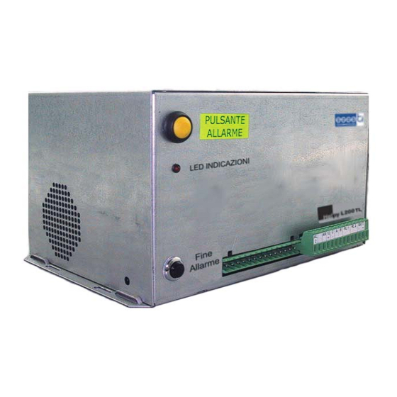
Page 7: Description
UNCTIONALITIES AND EATURES • It can be connected to the fixed public telephone network (standard operation mode) or to the GSM line (by installing the Esse-ti GSM200 proprietary module). • Types of alarm: Emergency-call alarm: max. 2 pushbuttons, of which, typically, one button for the elevator car and one optional button for the pit. - Page 8 Pre-recorded messages that identify the type of alarm (not customizable). • Management of ALARM GIVEN INDICATOR LIGHT and ALARM RECORDED INDICATOR LIGHT. • 1 relay for door-opener. • Local Programming through the local telephone. Remote programming through DTMF telephone or Esse-ti programming software. Page 8 DESCRIPTION...
- Page 9 The device has three priority levels associated with the alarm events. • High priority: emergency call buttons • Medium priority: technological alarms • Low priority: automatic test, diagnostics. Higher priority alarms temporarily abort lower priority alarms (thus the emergency call alarm aborts all the others). When the higher priority alarm ends, the system resumes the previously aborted alarm procedure.
-
Page 10: Operation
OPERATION PERATION IN IDLE STATE In idle state the device (if these checks are enabled): • Checks the battery status every 2 hours (“dead battery” technological alarm must have been previously enabled); • Checks the operation of the alarm system (diagnostics) every day at programmable time;... -
Page 11: Installation
INSTALLATION Recommendations • Keep the cables away from high voltage cables or other cables that may produce electromagnetic interference. • Do not lay telephone cables near the 230V mains. • To protect the telephone line, connect the terminal shown with in the connection diagram to the earth terminal. -
Page 12: Gsm200 Module Connection
GSM200 module connection Please see also the GSM200 User Manual. Check that jumper JP5 (on HelpyL200 TL) is in position 2-3. Connect the cable supplied with the GSM module to connector RJ-45. Page 12 INSTALLATION... -
Page 13: Connections
Connections Jumper JP5 for Telephone Line / GSM200 Module selection Programmer strip Serial plug for connection to elevator CPU Battery protection fuse (1A delayed) Battery Terminal blocks: INSTALLATION Page 13... - Page 14 Earth Telephone line input Telephone line output Local Telephone VV2+ Output Handsfree 2 VV2- Common Handsfree 2 Passive Handsfree Loudspeaker Output Passive Handsfree Microphone / Single Microphone Input Alarm input 1 Alarm input 2 Received alarm indicator light Output 12V Common terminal for inputs I1 and I2 Alarm filter input Auxiliary alarm input...
-
Page 15: Connection Diagram
Connection diagram INSTALLATION Page 15... - Page 16 It is recommended to extract the terminals, make the connections and place the terminals back into the correct position. Connect the local telephone (for programming and managing HelpyL200 TL) to the TL1 terminals (irrespective of the polarity) Connect the handsfree devices and the emergency-call pushbuttons: You can install max 1 passive handsfree terminal: Passive Handsfree 1 in the CAR: A, B, VV2-...
- Page 17 +12V AL1 or AL2 VV2- ALARM SIREN 8-12V, max 100mA EMERGENCY BUTTON LED EMERGENCY BUTTON Note: The LED is connected in series to the emergency call button and must have no resistance in series. Upon switching on, check that the device status LED stays steady for about 5 seconds and then starts flashing.
-
Page 18: Technical Specifications
TECHNICAL SPECIFICATIONS Tones Dialling Busy Confirmation and warning connection time elapsed Error from local Error from remote Status indicator LED’s PSTN Line Normal operation – no alarm, filer disabled Normal operation – no alarm, filer enabled Alarm in progress Page 18 TECHNICAL SPECIFICATIONS... - Page 19 GSM200 Module Normal operation – no alarm, filter disabled, no signal Normal operation – no alarm, filter disabled, low signal Normal operation – no alarm, filter disabled, medium signal Normal operation – no alarm, filter disabled, strong signal Normal operation – no alarm, filter enabled, no signal Normal operation –...
-
Page 20: Power Supply
External line tone recognition..............425 Hz HANDSHAKE tone recognition ..........1400 Hz, 2300 Hz Tele-programming protocol............PROPRIETARY Elevator control protocol ............PROPRIETARY Service centre protocol ..........Ademco Contact ID, Esse-ti Serial line output................TTL protected Telephone terminations Connections to the public telephone network.............1 Connections for extensions.................1... -
Page 21: Inputs/ Outputs
Cooling ................by natural convection Dimensions ................160x180x80 mm. Weight ......................3 Kg. CE conformity declaration Esse-ti s.r.l., with registered seat in Zona Ind. Squartabue, I-62019 Recanati (MC), Italy, hereby declares that this device complies with the following standards: • TBR21 (Attachment requirements for pan-European approval for... - Page 22 No maintenance operations are required on the device. Only check the battery charge status (this operation can be remotely performed with the ESSE-TI remote programming system)and fuse integrity. Following is a list of information that the elevator owner must provide to the rescue service.
- Page 23 Helpy L200 TL Release 06 Apr 2007...
Need help?
Do you have a question about the Helpy L200 TL and is the answer not in the manual?
Questions and answers