
Subscribe to Our Youtube Channel
Related Manuals for Esse-ti HELPY COMPACT-V R


Summary of Contents for Esse-ti HELPY COMPACT-V R
- Page 1 Alarm system for elevators compliant with the European Standard EN 81-28:2018 HELPY COMPACT-V R QUICK GUIDE 7IS-80542 29/11/2022...
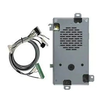
- Page 2 DESCRIPTION Autodialer specifically designed for retrofitting behind the elevator car panel. Back-up battery connector Micro SD Card slot Device status LED Serial port for PC connection Reset pushbutton Terminal blocks G Built-in loudspeaker Given alarm indicator light Received alarm indicator light Built-in microphone M RJ11 connector for local telephone Page 2...
-
Page 3: Terminal Blocks
TERMINAL BLOCKS Power supply input (10-30 Vdc) — Negative Alarm input Reset input 2 (freely programmable) Filter input (freely programmable) Common terminal for inputs AL1 and IN1 12 Vdc output (max. 100 mA) Received alarm indicator light (12 Vdc) Given alarm indicator light (12 Vdc) —... - Page 4 CONNECTING THE SPEAKER UNITS Helpy Compact-V R comes with a built-in speaker unit. It is also possible to connect to the Helpy Compact-V R up to 2 passive speaker units or cables with microphone. ➢ Make the connections as shown in the table below: HELPY COMPACT-V R MAX.
- Page 5 CONNECTING THE EMERGENCY CALL BUTTONS ➢ Connect, following one of the diagrams shown below, the pushbuttons. Car pushbutton It is possible to connect (inside the elevator car) voltage free contact pushbuttons or powered pushbuttons. Voltage free contact pushbuttons Powered pushbuttons (12-24 Vdc) – 2 solutions CONNECTING THE EMERGENCY CALL BUTTONS Page 5...
- Page 6 Page 6 CONNECTING THE EMERGENCY CALL BUTTONS...
- Page 7 The RECEIVED ALARM INDICATOR LIGHT (green) switches on when communication is established. Helpy Compact-V R comes with built-in indicator lights. It is also possible to connect external indicator lights. ➢ Connect, following the diagram shown below, the external indicator lights to the Helpy Compact-V R.
-
Page 8: Other Connections
OTHER CONNECTIONS ONNECTING THE TELEPHONE LINE PSTN line or universal gateway (2G/3G/4G) ➢ Connect the telephone line to LTI terminals. ➢ Connect the ground terminal (indicated by ), to a ground socket in order to increase the PSTN line protection. ONNECTING THE LOCAL TELEPHONE ➢... -
Page 9: Wiring Diagram
WIRING DIAGRAM WIRING DIAGRAM Page 9... - Page 10 MINIMUM OPERATIONS TO VERIFY PROPER INSTALLATION 1. PROGRAMMING ➢ Access to programming: lift the local telephone handset and dial The programming activated message will be heard. ➢ Program a telephone number for the emergency-call alarm: dial <telephone number> ➢ Record the identification message of the specific elevator, which is meant to contain all necessary information concerning the elevator location: dial and, after the “Correct”...
-
Page 11: Resetting The Alarm
The voice messages will be heard. ➢ Press to speak with the trapped person. mode: immediate and automatic two-way communication (no messages) ➢ Answer by the called party. ➢ Speak with the trapped person. 4. RESETTING THE ALARM Note: the alarm reset mode can be configured with the “Alarm reset mode”... -
Page 12: Using The Reset Button
* <Password> #. Pressing longer (10 seconds) Allows to reset the device. By pressing longer, the Helpy Compact-V R will be re-started with no need to disconnect the power supply. Note: it is also possible to reset the device through the code 995*0#. -
Page 13: Basic Programming
< INSTALLER or OPERATOR PASSWORD > PROGRAMMING (factory default: SOURCE RECEIVER emergency- — call button battery USER alarm * periodic automatic test ESSE-TI call * … — (X..X = telephone number, (position TELEPHONE max. 20 — (only with from 01 to NUMBERS digits;... -
Page 14: Listen To Messages
BASIC PROGRAMMING DELETE A TELEPHONE (position from 01 to NUMBER (INST) WEEKDAY SUNDAY MONDAY TUESDAY DATE * (dd) (mm) (yy) (INST) WEDNESDAY THURSDAY * to be FRIDAY reprogrammed in SATURDAY case of turn off TIME * (hhmm from 0000 to 2359) (INST) identification message... - Page 15 201 XX 11 Y <telephone number> # (INST) where XX= position (from 01 to 24) Y= notification mode (2= user, 3= Esse-ti, 4= CLI, 5= SMS only with 4G.VoLTE, 6= P100) Frequency (days, from 1 to 9; factory default 3) (hhmm from 0000 to 2359;...
-
Page 16: Restore Factory Settings
BASIC PROGRAMMING RESTORE FACTORY SETTINGS (INST) Page 16 PROGRAMMING... -
Page 17: Advanced Programming
Advanced programming ADVANCED PROGRAMMING CHANGE THE INSTALLER … PASSWORD “0” (old) (new) (new) (INST) CHANGE THE OPERATOR … PASSWORD “1” (old) (new) (new) (INST) INPUTS input NORMALLY type (1=AL1 OPEN/CLOSED (0=normally closed 2=EOA (INST) 1=normally open) 3=IN1) EOA=alarm input / IN1=filter input EOA=auxiliary input / IN1=filter input EOA=alarm input / IN1=gong input EOA=auxiliary input / IN1=gong input... -
Page 18: Input Configuration
(INST) 3= Esse-ti 4= CLI 6= P100 - if receiver 3, set the Esse-ti protocol ID: 222 YYYYYYYYYY - if receiver 6, set the P100 protocol ID: 223 ZZZZZZZZ# - if receiver 6, customize the P100 protocol codes using the e-stant software (programming code 203) Note: EOA and IN1 are automatically configured as normally closed;... -
Page 19: Filter Bypass
ADVANCED PROGRAMMING BEEP ENABLING beep disabled WHEN PUSHBUTTON IS PRESSED beep enabled (INST) NO EXTERNAL POWER SUPPLY disabled alarm ALARM * (INST) enabled alarm with XX minutes delay * only with back-up (from 01 to 99) battery THRESHOLD OF THE NO …... - Page 20 ADVANCED PROGRAMMING PLAYBACK OF never “COMMUNICA- TION ACTIVA- TED” MESSAGE only in case of remote connection WHEN THE SPEAKER UNIT IS ACTIVATED always (INST) two-way communication established after TWO-WAY input of "Communication activation" code COMMUNICATIO automatic two-way communication N MODE DURING established after messages AN ALARM (INST)
- Page 21 ADVANCED PROGRAMMING MULTI- LANGUAGE COURTESY (second language) (third language) MESSAGE (INST) (country: 00 IT/SM/AL/BA/GM/MK/MT/NO, 01 GB/AE, 02 DE/LB/LU, 03 FR/GP/GF, 04 PL, 05 PT, 06 RU/BY, 07 ES/AD/CY, 08 BG/BR/KY/ TONE DECODER DK/ID/IR/IS/KW/MO/MW/MX/PY/UY/VE/YE/ZM/ (INST) FO/LR, 10 HR, 11 GR/EE/FI, 12 NL/AW/VU, (default value may 13 SI, 14 HU, 15 IL, 16 AT, 17 AU, 18 CH, vary depending on...
- Page 22 ADVANCED PROGRAMMING WAITING TIME BETWEEN TECHNOLOGICAL (minutes, from 01 to 99; OR TEST CALLS 00=30 seconds, factory default 02) TO THE SAME NUMBER (INST) DURATION OF CALL TO EACH (seconds, from 15 to 60) NUMBER (INST) CLI CALL DURATION (seconds, from 00 to 99; factory default 10) (INST) AUTOMATIC (ring number, from 1 to 9;...
-
Page 23: Remote Programming
Local programming via e-stant software It is possible to program Helpy Compact-V R via computer by using the USB/serial proprietary cable and the dedicated e-stant software. e-stant software also allows to: - update the firmware of the Helpy Compact-V R... -
Page 24: Local Use
DEACTIVATE CONVERSATION EXTERNAL CALLS <TELEPHONE NUMBER> Use remotely with Helpy Compact-V R at rest ➢ Call Helpy Compact-V R and wait for a response. ➢ Listen to the elevator identification message, if present. ➢ Dial to speak with all speaker units. -
Page 25: Device Status Led
SIGNALS Device status LED Normal operation (no alarm) Alarm Voice connection Low battery (max. 1-hour operation in idle state) Absence of telephone line Button failure SIGNALS Page 25... - Page 26 Given alarm indicator light (yellow) Alarm Received alarm indicator light (green) Voice connection Missed test call notification (EN 81-28:2018) The Given alarm indicator light and the Received alarm indicator light flash in opposition to indicate the failure of the automatic test call. The flashing sequence ends after the next successful test call or emergency call.
-
Page 27: Eu Declaration Of Conformity
EU DECLARATION OF CONFORMITY Hereby, Esse-ti S.r.l. declares that the equipment type Helpy Compact-V R is in compliance with Directives 2014/35/EU - 2014/33/EU - 2014/30/EU. The full text of the EU declaration of conformity is available from the following Internet address: https://www.esse-ti.it/en/dichiarazioni-di-conformita... - Page 28 Esse-ti S.r.l. Via G. Capodaglio, 9 62019 Recanati (MC) – ITALY Tel. +39 071 7506066 www.esse-ti.it support@esse-ti.it...
Need help?
Do you have a question about the HELPY COMPACT-V R and is the answer not in the manual?
Questions and answers