
Related Manuals for Esse-ti HELPY QUICK INTL


Summary of Contents for Esse-ti HELPY QUICK INTL
- Page 1 Alarm system for elevators QUICK GUIDES: HELPY QUICK INTL HELPY QUICK-TL INTL ST61 INTL 20/03/2017...
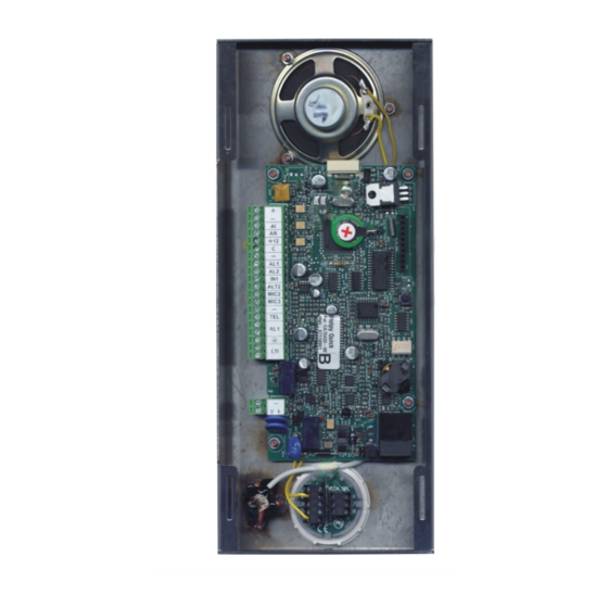
- Page 2 DESCRIPTION ELPY UICK Built-in loudspeaker Connector for Esse-ti power supply (12Vdc) LED indicating device operation (red) LED indicating GSM200 signal strength (green) Connector for FlashKey Reset pushbutton RJ45 connector for GSM200 module Jumpers for Telephone Line / GSM200 Module selection Pushbutton (two contacts): .C2: common...
- Page 3 Terminal blocks: 12Vdc power supply input or 12Vdc output (max. 100mA, if present Esse-ti power supply) Negative pole Given alarm indicator light Received alarm indicator light 12Vdc output (max. 100mA) Common terminal for inputs AL1 and IN1 Negative pole Alarm input 1...
- Page 4 HELPY QUICK-TL Connector for external LEDs Connector for built-in loudspeaker Built-in loudspeaker Connector for internal power supply Connector for FlashKey Connector for external reset pushbutton Reset pushbutton Battery RJ45 connector for GSM200 module Jumpers for Telephone Line / GSM200 Module selection Built-in microphone Connector for built-in microphone Terminal blocks...
- Page 5 Terminal blocks: 12Vdc output (max. 100mA) Negative pole Given alarm indicator light Received alarm indicator light 12Vdc output (max. 100mA) Common terminal for inputs AL1 and IN1 Negative pole Alarm input 1 Alarm input 2 Filter input ALT2 Output for connecting loudspeaker of passive handsfree terminal MIC2 Input for connecting microphone of passive handsfree or...
- Page 6 Connector for built-in loudspeaker LED indicating device operation (red) LED indicating GSM200 signal strength (green) Built-in loudspeaker Connector for Esse-ti power supply (12Vdc) Connector for FlashKey Reset pushbutton RJ45 connector for GSM200 module Jumpers for Telephone Line / GSM200 Module selection...
- Page 7 Terminal blocks: 12Vdc power supply input or 12Vdc output (max. 100mA, if present Esse-ti power supply) Negative pole Given alarm indicator light Received alarm indicator light 12Vdc output (max. 100mA) Common terminal for inputs AL1 and IN1 Negative pole Alarm input 1...
-
Page 8: Connecting The Telephone Line
CONNECTING THE TELEPHONE LINE HELPY QUICK – ST61 The device allows the connection of a PSTN line or GSM line by means of the GSM200 module or a traditional GSM interface. PSTN line or traditional GSM interface Connect the ground terminal (indicated by ) to a ground socket in order to increase the telephone line protection. - Page 9 HELPY QUICK-TL The device allows the connection of a PSTN line or GSM line by means of the GSM200 module or a traditional GSM interface. PSTN line or traditional GSM interface Connect the ground terminal (indicated by ) to a ground socket in order to increase the telephone line protection.
- Page 10 CONNECTING EMERGENCY PUSHBUTTON AL1 AND FILTER IN1 HELPY QUICK-TL – ST61 It is possible to connect (inside the elevator car) voltage free contact pushbuttons or powered pushbuttons. Voltage free contact pushbuttons Connect the filter contact to IN1 terminal and – (negative pole). CONNECTING EMERGENCY PUSHBUTTON AL1 AND FILTER IN1 Page 10...
- Page 11 Powered pushbuttons (12~ 24Vdc) Connect the filter contact to IN1 terminal and – (negative pole). Connect the filter contact to IN1 terminal and +12V terminal. Page 11 CONNECTING EMERGENCY PUSHBUTTON AL1 AND FILTER IN1...
-
Page 12: Wiring Diagrams
WIRING DIAGRAMS HELPY QUICK WIRING DIAGRAMS Page 12... - Page 13 HELPY QUICK-TL Wiring diagram with active handsfree terminal in the pit Page 13 WIRING DIAGRAMS...
- Page 14 Wiring diagram with passive handsfree terminal in the elevator car bottom WIRING DIAGRAMS Page 14...
- Page 15 ST61 Wiring diagram with active handsfree terminal in the pit Page 15 WIRING DIAGRAMS...
- Page 16 Wiring diagram with passive handsfree terminal in the elevator car bottom WIRING DIAGRAMS Page 16...
- Page 17 CORRECT OPERATION CHECKLIST 1. PROGRAMMING Access to programming: lift the local telephone handset and dial You will hear the dialling tone (one longer tone followed by a shorter tone). Only if GSM200 module is present: dial Program a telephone number for the emergency-call alarm: dial <telephone number>...
- Page 18 4. RESETTING AN ALARM mode: reset by “End” code (factory default) Press to end the alarm. mode: automatic reset Hang up or press to end the alarm. Remark: you can choose the 1 or the 2 mode with the “Alarm reset mode”...
-
Page 19: Basic Programming
GSM200 module (INST) SOURCE RECEIVER emergency- ADEMCO call button technological USER alarms … (X…X = periodic TELEPHONE telephone ESSE-TI (position test call NUMBERS number, from 01 (INST) max 20 to 12) digits) alarm sent alert (only with notification GSM200) alarm... - Page 20 BASIC PROGRAMMING DELETING TELEPHONE (position from NUMBER 01 to 12) (INST) HANDSFREE handsfree activation by CONNECTION “Handsfree activation” code MODE (INST) automatic handsfree activation ALARM RESET automatic reset MODE (INST) alarm reset by “End” code WEEKDAY SUNDAY MONDAY TUESDAY DATE (INST) (dd) (mm) (yy)
- Page 21 BASIC PROGRAMMING ADEMCO / P100 max 10-digits ID: PROTOCOL ID (INST) ESSE-TI 10-digits ID: PROTOCOL ID (INST) Frequency (days, from 1 to 9; factory default 3) Time (hhmm; from 0000 to 2359) AUTOMATIC TEST DATA automatic test disabled Automatic (INST)
-
Page 22: Advanced Programming
Advanced programming ADVANCED PROGRAMMING CHANGING THE INSTALLER … (old) (new) (new) PASSWORD (INST) CHANGING THE OPERATOR … (old) (new) (new) PASSWORD (INST) Italian English German French LANGUAGE (INST) Polish Portuguese Russian Spanish Italy/Switzerland/Portugal/Poland/Bulgaria England Israel Greece TONE DECODER Austria (digital) SETTING Germany (INST) - Page 23 ADVANCED PROGRAMMING FILTER disabled ACTIVATION (INST/OPER) enabled normally closed FILTER INPUT NC/NO (INST/OPER) normally open “ACKNOWLEDGE” CODE … (from 1 to 3 digits; factory default 5) (INST) “HANDSFREE ACTIVATION” … (from 1 to 3 digits; factory default 0) CODE (INST) “END”...
- Page 24 ADVANCED PROGRAMMING CONNECTION TIME AFTER AUTOMATIC (minutes, from 1 to 9) ANSWER (INST) OFFSET FLOOR MESSAGES (offset, from 0 to 9) (INST) same behavior as output AI same behavior as output AR active for mains failure RELAY SETTINGS door opener (INST) active as long as the emergency alarm progresses...
-
Page 25: Programming Message Format
PROGRAMMING VIA SMS (ONLY WITH GSM200) All parameters programmable locally by the local telephone may also be set via SMS. Programming via SMS is possible by any mobile phone or other device supporting SMS. An SMS notifying that programming has been completed will be sent back by the autodialer to the same telephone number that forwarded the programming SMS. - Page 26 - phone number 0717506066 in the first location associated with Emergency call (source) under User mode (receiver) - phone number 0717506105 in the second location associated with Automatic test call (source) under Esse-ti protocol mode (recipient) Programming message: ET-HL3 *0# 2101120717506066# 2102330717506105#...
- Page 27 In the tables below: : lift the local telephone handset; : lift the local telephone handset and dial to access programming. Local LOCAL USE CONVERSATION CONVERSATION WITH THE CAR CONVERSATION HANDSFREES IN ELEVATOR CAR WITH ONE PIT ACTIVE HANDSFREE HANDSFREE TERMINAL DEACTIVATE ALL...
- Page 28 Esse-ti s.r.l. Via G. Capodaglio, 9 62019 Recanati (MC) – ITALY Tel. +39 071 7506066 Fax +39 071 7506057 www.esse-ti.it e-mail: support@esse-ti.it...
Need help?
Do you have a question about the HELPY QUICK INTL and is the answer not in the manual?
Questions and answers