
Related Manuals for Esse-ti HELPY COMPACT Series


Summary of Contents for Esse-ti HELPY COMPACT Series
-
Page 1: Quick Guide
Alarm system for elevators compliant with the European Standard EN 81-28:2018 HELPY COMPACT QUICK GUIDE To download User guides in other languages please scan the QR-code or visit https://www.esse-ti.it/en/manuals 7IS-80465 31/10/2019... -
Page 2: Built-In Battery
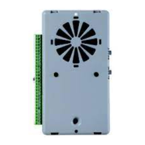
DESCRIPTION Autodialer specifically designed for retrofitting behind the elevator car panel. A Terminal blocks B Built-in loudspeaker C Given alarm indicator light D Received alarm indicator light E Built-in microphone F Device status LED ( ) G Reset pushbutton H Serial port for PC connection Alarm pushbutton L Micro SD Card slot Helpy Compact models... -
Page 3: Terminal Blocks
TERMINAL BLOCKS PSTN-line or universal gateway input PSTN-line or universal gateway input Ground terminal for PSTN-line Output for domestic telephone line Output for domestic telephone line Local telephone — Negative RL1 NO Relay (normally open contact) RL1 NC Relay (normally closed contact) RL1 C Relay (common contact) Power supply input (12 Vdc - 30 Vdc) - Page 4 MIC2 AMP Input for connecting microphone of pit amplified passive speaker unit MIC3 AMP Input for connecting microphone of pit amplified passive speaker unit — Negative Alarm input Given alarm indicator light (0 Vdc) Received alarm indicator light (0 Vdc) : can be connected to a block –, to the block +12 or to an external reference : allows to connect voltage free contact pushbuttons (NO or NC) or powered pushbuttons : allows to connect voltage free contact (NO or NC)
-
Page 5: Installation
INSTALLATION Helpy Compact can be fixed with 2 screws or with the pre-drilled double-sided adhesive rubber supplied. Fixing with double-sided adhesive rubber Remove the film from one side of the adhesive rubber. Attach the adhesive rubber to the COP, paying attention that the hole reserved for the microphone of the Helpy Compact (E in the picture at page 2) corresponds to a free hole of the COP. - Page 6 CONNECTING THE SPEAKER UNITS Helpy Compact comes with a built-in speaker unit. It is also possible to connect to the Helpy Compact up to 2 passive speaker units, amplified passive speaker units or cables with microphone. Passive speaker units or cables with microphone can be installed on top and bottom of elevator car.
- Page 7 CONNECTING THE EMERGENCY CALL BUTTONS Car pushbutton It is possible to connect (inside the elevator car) voltage free contact pushbuttons or powered pushbuttons. Connect, following one of the diagrams shown below, the car pushbutton. Voltage free contact pushbuttons Powered pushbuttons (12-24 Vdc) – 2 solutions CONNECTING THE EMERGENCY CALL BUTTONS Page 7...
- Page 8 Other pushbuttons It is possible to use for the pit, the top and the bottom of elevator car voltage free contact pushbuttons (NO or NC). Connect, following the diagram shown below, the external pushbutton. Page 8 CONNECTING THE EMERGENCY CALL BUTTONS...
- Page 9 CONNECTING THE FILTER INPUT Connect, following one of the diagrams shown below, the filter contact. CONNECTING THE FILTER INPUT Page 9...
- Page 10 CONNECTING THE INDICATOR LIGHTS The GIVEN ALARM INDICATOR LIGHT (yellow) switches on after pressing the emergency button to indicate the beginning of the alarm procedure. The RECEIVED ALARM INDICATOR LIGHT (green) switches on when the alarm call is answered. Some Helpy Compact models come with built-in indicator lights. It is also possible to connect external indicator lights.
-
Page 11: Other Connections
It is possible to configure the AL2 input of Helpy Compact as auxiliary input (NO or NC). Connect the external contact to AL2 and – terminals. EPLACING BATTERY ATTENTION Only use replacement batteries supplied by Esse-ti. OTHER CONNECTIONS Page 11... - Page 12 Example of wiring diagram with speaker unit in the pit Page 12 OTHER CONNECTIONS...
- Page 13 Example of wiring diagram with speaker unit in the elevator car bottom OTHER CONNECTIONS Page 13...
-
Page 14: Turning On / Turning Off
TURNING ON / TURNING OFF URNING ON Connect the external (12 Vdc - 30 Vdc) power supply to + and — terminals. Helpy Compact lights up and the device status LED starts flashing. URNING OFF 5HL-601 Disconnect the external (12 Vdc - 30 Vdc) power supply from + and — terminals. - Page 15 MINIMUM OPERATIONS TO VERIFY PROPER INSTALLATION 1. PROGRAMMING Access to programming: lift the local telephone handset and dial The programming activated message will be heard. Program a telephone number for the emergency-call alarm: dial <telephone number> Record the identification message of the specific elevator, which is meant to contain all necessary information concerning the elevator location: dial and, after the “Correct”...
-
Page 16: Resetting The Alarm
mode: two-way communication established after input of “Communication activation” code Answer by the called party. The voice messages will be heard. Press to speak with the trapped person. mode: immediate and automatic two-way communication (no messages) Answer by the called party. ... -
Page 17: Using The Reset Button
SING THE RESET BUTTON Note: the reset operation does not alter the previously set parameters. Use of the reset pushbutton (G in the picture at page 2): Pressing shortly Allows to interrupt an alarm call. By pressing shortly you get the same result as lifting the handset of the local telephone and entering * <Password>... -
Page 18: Basic Programming
< INSTALLER or OPERATOR PASSWORD > EXITING THE PROGRAMMING (factory default: SOURCE RECEIVER emergency- — call button battery USER alarms * periodic automatic test ESSE-TI call * … — (X..X = telephone number, (position TELEPHONE — max. 20 (with from 01 to NUMBERS digits;... -
Page 19: Listen To Messages
BASIC PROGRAMMING DELETE A TELEPHONE (position from 01 to NUMBER (INST) WEEKDAY SUNDAY MONDAY TUESDAY DATE * (dd) (mm) (yy) (INST) WEDNESDAY THURSDAY * to be FRIDAY reprogrammed in SATURDAY case of turn off TIME * (hhmm from 0000 to 2359) (INST) identification message... - Page 20 AUTOMATIC TEST automatic test disabled DATA Automatic (INST) automatic test enabled (EN 81-28:2018) test alarm automatic test enabled (EN 81-28:2004) Make a test call manually PROTOCOLS Esse-ti IDENTIFICATION … (identification code) CODE P100 (INST) SPEAKER UNITS loudspeaker microphone VOLUME (from 1 to...
-
Page 21: Advanced Programming
Advanced programming ADVANCED PROGRAMMING CHANGE THE INSTALLER … PASSWORD “0” (old) (new) (new) (INST) CHANGE THE OPERATOR … PASSWORD “1” (old) (new) (new) (INST) function (00=not active 01=alarm input input 02=auxiliary input INPUTS SETTING (2=AL2 or 3=IN1) 03=reset input (INST) 04=filter input 05=gong input) (factory default:... - Page 22 ADVANCED PROGRAMMING EMERGENCY CALL BUTTONS DELAY (seconds, from 2 to 9; factory default 3) (INST) INPUTS input NORMALLY type (1=AL1 OPEN/CLOSED (0=normally closed 2=AL2 (INST) 1=normally open) 3=IN1) NO EXTERNAL disabled alarm POWER SUPPLY ALARM * (INST) enabled alarm with XX minutes delay * 5HL-600 only (from 01 to 99) BUILT-IN...
- Page 23 ADVANCED PROGRAMMING two-way communication established after input of "Communication activation" code TWO-WAY COMMUNICATIO automatic two-way communication established N MODE DURING after messages AN ALARM (INST) immediate and automatic two-way communication (no messages) automatic reset ALARM RESET MODE alarm reset by “End alarm” code (INST) automatic reset with local acknowledgement “PLAY...
- Page 24 ADVANCED PROGRAMMING (country: 00 IT/SM/AL/BA/GM/MK/MT/NO, 01 GB/AE, 02 DE/LB/LU, 03 FR/GP/GF, 04 PL, 05 PT, 06 RU/BY, 07 ES/AD/CY, 08 BG/BR/KY/ DK/ID/IR/IS/KW/MO/MW/MX/PY/UY/VE/YE/ZM/ TONE DECODER FO/LR, 10 HR, 11 GR/EE/FI, 12 NL/AW/VU, (INST) 13 SI, 14 HU, 15 IL, 16 AT, 17 AU/IE, 18 CH, 19 CN, 20 US/CA/JM/AI/AG/BB/BM/VG/DM/MS/ KN/TT/TC 21 BE, 22 QA, 23 SE, 24 IN, 25 TR, 26 CZ/SK/LT/MD, 27 TN/SA, 28 DZ, 29 MA,...
-
Page 25: Relay Setting
ADVANCED PROGRAMMING CLI CALL DURATION (seconds, from 00 to 99; factory default 10) (CLI) DTMF (from 1 to 9; factory default 2; GENERATOR DTMF duration=X*50 ms) (INST) MULTI-LINK FUNCTION (from 0 to 9; 1=master, 0=function disabled) (INST) same behaviour as outputs AI same behaviour as outputs AR active for external power failure door opener... - Page 26 - set a micro SD card to use for programming, customizing the messages and updating the firmware of the Helpy Compact. e-stant can be downloaded at the following link: https://www.esse-ti.it/en/download/software-request Programming via micro SD card The micro SD card properly set allows to:...
-
Page 27: Local Use
Local use : lift the local telephone handset : lift the local telephone handset and dial to access programming LOCAL USE CONVERSATION WITH ALL CONVERSATION SPEAKER UNITS PROGRAMMING … CONVERSATION CONVERSATION WITH ALL SPEAKER UNITS DEACTIVATE CONVERSATION EXTERNAL CALLS <TELEPHONE NUMBER> DOOR OPENER RELAY Use remotely with Helpy Compact at rest ... -
Page 28: Device Status Led
SIGNALS Device status LED ( ) Normal operation (no alarm) Alarm Voice connection Battery disconnected or low battery (max. 1-hour operation in idle state) Absence of telephone line Button failure Page 28 SIGNALS... - Page 29 Given alarm indicator light (yellow) Alarm Received alarm indicator light (green) Voice connection Missed test call notification (EN 81-28:2018) The Given alarm indicator light and the Received alarm indicator light flash in opposition to indicate the failure of the automatic test call. The flashing sequence ends after the next successful test call or emergency call.
- Page 30 NOTE Pagina 30 NOTE...
- Page 31 NOTE Page 31...
- Page 32 Esse-ti S.r.l. Via G. Capodaglio, 9 62019 Recanati (MC) – ITALY Tel. +39 071 7506066 Fax +39 071 7506057 www.esse-ti.it support@esse-ti.it...
Need help?
Do you have a question about the HELPY COMPACT Series and is the answer not in the manual?
Questions and answers