
Subscribe to Our Youtube Channel
Related Manuals for Esse-ti HELPY 2W-V BASIC


Summary of Contents for Esse-ti HELPY 2W-V BASIC
- Page 1 Alarm system for elevators compliant with the European Standard EN 81-28:2018 HELPY 2W-V BASIC QUICK GUIDE 31/07/2019...
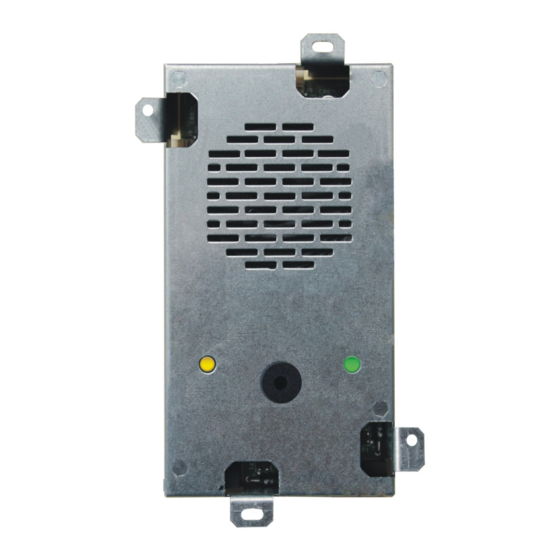
- Page 2 DESCRIPTION Autodialer specifically designed for retrofitting behind the elevator car panel. A Connector for Esse-ti power supply (12 Vdc) B Micro SD Card slot C Device status LED D Serial port for PC connection E Reset pushbutton F Terminal blocks...
-
Page 3: Terminal Blocks
TERMINAL BLOCKS Power supply input 12 Vdc or 24 Vdc Negative Given alarm indicator light (12 Vdc) Received alarm indicator light (12 Vdc) 12 Vdc output (max. 100 mA) Common terminal for inputs AL1 and IN1 Negative Alarm input Alarm input 2 / Auxiliary input / Reset input Filter input... - Page 4 CONNECTING THE SPEAKER UNITS Helpy 2W-V comes with a built-in speaker unit. It is also possible to connect to the Helpy 2W-V up to 2 passive speaker units (or cables with microphone) combined to the built-in speaker unit. Note: the passive speaker unit can be installed at max. 6 m distance from Helpy 2W-V by using a shielded cable.
- Page 5 CONNECTING THE EMERGENCY CALL BUTTONS Car pushbutton It is possible to connect (inside the elevator car) voltage free contact pushbuttons or powered pushbuttons. Connect, following one of the diagrams shown below, the car pushbutton. Voltage free contact pushbuttons Powered pushbuttons (12~24Vdc) – 2 solutions CONNECTING THE EMERGENCY CALL BUTTONS Page 5...
- Page 6 Passive speaker unit pushbuttons In case of passive speaker units without built-in pushbutton it is possible to use voltage free contact pushbuttons (NO or NC). Connect, following the diagram shown below, the external pushbutton. Page 6 CONNECTING THE EMERGENCY CALL BUTTONS...
- Page 7 CONNECTING THE FILTER INPUT Connect, following one of the diagrams shown below, the filter contact. CONNECTING THE FILTER INPUT Page 7...
- Page 8 CONNECTING THE INDICATOR LIGHTS The GIVEN ALARM INDICATOR LIGHT (yellow) switches on after pressing the emergency button to indicate the beginning of the alarm procedure. The RECEIVED ALARM INDICATOR LIGHT (green) switches on when the alarm call is answered. Some Helpy 2W-V models come with built-in indicator lights. It is also possible to connect external indicator lights.
-
Page 9: Other Connections
OTHER CONNECTIONS ONNECTING THE TELEPHONE LINE PSTN line or universal gateway (2G/3G/4G) Connect the ground terminal (indicated by ), to a ground socket in order to increase the telephone line protection. Connect the telephone line to terminal LTI. ONNECTING THE LOCAL TELEPHONE ... -
Page 10: Wiring Diagram
WIRING DIAGRAM Page 10 WIRING DIAGRAM... - Page 11 MINIMUM OPERATIONS TO VERIFY PROPER INSTALLATION 1. PROGRAMMING Access to programming: lift the local telephone handset and dial The programming activated message will be heard. Program a telephone number for the emergency-call alarm: dial <telephone number> Record the identification message of the specific elevator, which is meant to contain all necessary information concerning the elevator location: dial and, after the “Correct”...
-
Page 12: Resetting The Alarm
Answer by the called party. The voice messages will be heard. Press to speak with the trapped person. mode: immediate and automatic two-way communication (no messages) Answer by the called party. Speak with the trapped person. 4. - Page 13 SING THE RESET BUTTON Note: the reset operation does not alter the previously set parameters. Use of the reset pushbutton (E in the picture at page 2): Pressing shortly Allows to interrupt an alarm call. By pressing shortly you get the same result as lifting the handset of the local telephone and entering * <Password>...
-
Page 14: Basic Programming
< INSTALLER or OPERATOR PASSWORD > EXITING THE PROGRAMMING (factory default: SOURCE RECEIVER emergency- — call button battery USER alarms * periodic automatic test ESSE-TI call * … (X..X = — telephone number, TELEPHONE (position max. 20 NUMBERS from 01 to — —... -
Page 15: Listen To Messages
(hang up) (INST) courtesy message (max. 25 s) identification LISTEN TO message MESSAGES (listen) (INST/OPER) courtesy message LOW BATTERY disabled alarm ALARM (INST) enabled alarm REPLACE disabled alarm BATTERY ALARM (with Esse-ti power supply) enabled alarm (INST) PROGRAMMING Page 15... - Page 16 AUTOMATIC TEST automatic test disabled DATA Automatic (INST) automatic test enabled (EN 81-28:2018) test alarm automatic test enabled (EN 81-28:2004) Make a test call manually PROTOCOLS Esse-ti IDENTIFICATION … (identification code) CODE P100 (INST) SPEAKER UNITS loudspeaker microphone VOLUME (from 1 to...
-
Page 17: Advanced Programming
AL2=reset input / IN1=filter input (INST) AL2=alarm input / IN1=reset input AL2=auxiliary input / IN1=reset input NO EXTERNAL POWER SUPPLY disabled alarm ALARM (with Esse-ti enabled alarm with XX minutes delay power supply) (from 01 to 99) (INST) FILTER disabled ACTIVATION... -
Page 18: Filter Bypass
ADVANCED PROGRAMMING FILTER BYPASS (seconds, from 15 to 30) (INST) ALARM AI indicator light lit and courtesy message OPERATION WITHOUT AI indicator light unlit and no courtesy message TELEPHONE LINE (INST) AI indicator light lit and no courtesy message REPEATS OF COURTESY (seconds between two courtesy messages, from MESSAGE... - Page 19 ADVANCED PROGRAMMING “EXCLUSION” CODE … (from 1 to 3 digits; factory default 1) (INST) RESTORE identification message FACTORY MESSAGES courtesy message (INST) (language: 00 Italian, 01 English, 02 German, LANGUAGE 03 French, 04 Polish, 05 Portuguese, (INST) 06 Russian,07 Spanish) MULTI-ANGUAGE COURTESY MESSAGE...
-
Page 20: Relay Setting
ADVANCED PROGRAMMING AUTOMATIC (ring number, from 1 to 9; ANSWER 0=disabled; factory default 2) (INST) OPERATION programming mode MODE AFTER AUTOMATIC ANSWER direct connection with the car (INST) CONNECTION DURATION AFTER AUTOMATIC (minutes, from 1 to 9) RESPONSE (INST) CLI CALL DURATION (seconds, from 00 to 99;... - Page 21 - set a micro SD card to use for programming, customizing the messages and updating the firmware of the Helpy 2W-V. e-stant can be downloaded at the following link: https://www.esse-ti.it/en/download/software-request Programming via micro SD card The micro SD card properly set allows to:...
-
Page 22: Local Use
Local use : lift the local telephone handset : lift the local telephone handset and dial to access programming LOCAL USE CONVERSATION WITH THE CONVERSATION SPEAKER UNITS PROGRAMMING … CONVERSATION CONVERSATION WITH THE SPEAKER UNITS DEACTIVATE CONVERSATION EXTERNAL CALLS <TELEPHONE NUMBER> DOOR OPENER RELAY Use remotely with Helpy 2W-V at rest ... -
Page 23: Device Status Led
SIGNALS Device status LED Normal operation (no alarm) Alarm Voice connection Battery disconnected or low battery (max. 1-hour operation in idle state) Absence of telephone line Button failure SIGNALS Page 23... - Page 24 Given alarm indicator light (yellow) Alarm Received alarm indicator light (green) Voice connection Missed test call notification The Given alarm indicator light and the Received alarm indicator light flash in opposition to indicate the failure of the automatic test call. The flashing sequence ends after the next successful test call or emergency call.
-
Page 25: Eu Declaration Of Conformity
EU DECLARATION OF CONFORMITY Hereby, Esse-ti S.r.l. declares that the equipment type Helpy 2W-V is in compliance with Directives 2014/30/EU - 2014/33/EU - 2014/35/EU. The full text of the EU declaration of conformity is available from the following Internet address: https://www.esse-ti.it/en/dichiarazioni-di-conformita... - Page 26 NOTE Pagina 26 NOTE...
- Page 27 NOTE Page 27...
- Page 28 Esse-ti S.r.l. Via G. Capodaglio, 9 62019 Recanati (MC) – ITALY Tel. +39 071 7506066 Fax +39 071 7506057 www.esse-ti.it support@esse-ti.it...
Need help?
Do you have a question about the HELPY 2W-V BASIC and is the answer not in the manual?
Questions and answers