Advertisement
Available languages
Available languages
Quick Links
Advertisement

Related Manuals for Njoy UPCMTOP960HASCG02B


Summary of Contents for Njoy UPCMTOP960HASCG02B
- Page 1 Aster 6/10KT Black/White User Manual UPCMTOP960HASCG01B Manual de utilizare UPCMTOP960HASCG02B UPCMTOP910KASCG01B 268.20.22.0 Before using this product, carefully read all product documentation and retain it for future reference.
-
Page 2: Package Contents
Thank you for purchasing our products! Please read this manual before using the product. nJoy is a brand of power and backup protection products that create solutions for multiple levels of environment complexity, residential to industrial. This UPS will protect your electronic equipment from physical damage and will provide emergency battery backup power to prevent data loss in the event of power problems. -
Page 3: Product Overview
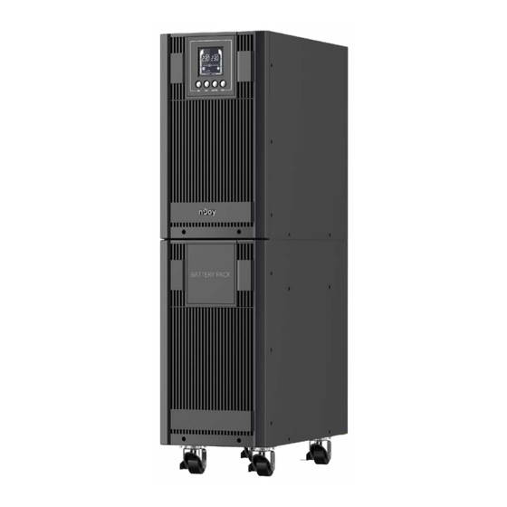
Product overview Front View Aster 6KT/10KT Fig.1-1 LCD display Settings buttons * For details please refer to - page 10 chapter 6.2. Button functions... - Page 4 Back View Aster 6KT/10KT Fig.1-2...
- Page 5 Fans. Input Circuit Breaker:The circuit breaker provides optimal overload protection. Battery input Connector: Use this input Connector to daisy chain the next Battery module. USB port: This port allows connection and communication from the USB port on the computer to the UPS unit. The UPS communicates its status to the software.
-
Page 6: Installation
Installation The system must be installed and wired only by qualified electricians in accordance with applicable safety regulations! For safety, please cut off the mains power switch before installation! When installing the electrical wiring, please note the nominal amperage of your incoming feeder. 5.1. - Page 7 It is suggested to install an external isolating device against backfeed current between mains input and UPS. After the device is installed, a warning label must be attached to the external AC connector with the following text: RISK OF BACKFEED CURRENT. Isolate the UPS with the isolating device before operating on this circuit, then check for hazardous voltage between all terminals.
- Page 8 Connect other input and output wires to the corresponding input and output terminals according to the following diagram. Fig. 3 Input and output terminal block wiring diagram Note: Make sure that the input and output wires and the input and output terminals are connected tightly.
- Page 9 5.2 EPO Connection EPO (Emergency power off): when the emergency occurs, such as the failure of load, the UPS can cut off the output at once by operating the EPO port manually. The connection: Normally the EPO connector is closed with a wire on the rear panel (Fig.4-4), which is supplied in the accessory.
- Page 10 Please follow steps below to install batteries inside Aster 6KT / Aster 10KT UPS: Step 1: Remove side panels and battery holders from each side of the UPS Front Panel Step 2: Place 4 batteries on the left side of the UPS (as you look from behind the UPS) as shown in picture below.
- Page 11 Step 3: Connect the batteries as shown in below picture. Step 4: Turn the 4 batteries placed initially and add two more batteries, as in the picture below...
- Page 12 Step 5: Connect the batteries to each other as in the diagram below: Step 6: Pass the cable through the passage slot F, as in the photo below...
- Page 13 Step 7: Place back the holders af the batteries Step 8: On the right side of the UPS, put 10 batteries as shown in the picture below Right side view...
- Page 14 Step 9: Connect the batteries with cables as shown in the picture below: Cables from the other side Step 10: Connect the first two batteries (as you look from the front of the UPS) with the cables connected to UPS as shown in below picture. Cables connected to UPS main...
- Page 15 Step 11: Place back battery holders, and after that, side panels of the UPS...
-
Page 16: Operation
Operation 6.1 Display Panel 6.2. Button functions Button Operation Description Press this button to turn on UPS. In line mode, ECO mode, or converter mode, press the “ON” button for 5 seconds to activate the battery test. Press this button to turn off UPS. Press this button for 5 seconds to get into setting mode while in bypass mode, or standby mode. - Page 17 6.3. LCD Operation Operation mode Description LCD display Line mode Utility will provide energy to loads. It will also charge the battery at the same time. Battery mode The unit will provide output power from battery. ECO mode When the input volt- age is within voltage regulation range, UPS will bypass voltage...
- Page 18 Converter mode When input frequency is within 40Hz to 70Hz, the UPS can be set at a constant output fre- quency, 50Hz or 60Hz. Standby mode Utility will charge the battery and no output voltage until switch on the UPS. Warning mode The UPS is warning be- cause of overload.
- Page 19 LCD displays 6 pages in total: Left: AC INPUT(Voltage) V 1(default) Right: OUTPUT(Voltage) V Left: INPUT(Frequency) Hz Right: OUTPUT(Frequency) Left: W load percent (%) Right: OUTPUTXXX KW Left: VA load percentage (%) Right: OUTPUTXXX KVA...
- Page 20 Left: Battery capacity percentage (%) Right: Battery voltage(V) Left: Backup Time(Min) Right: Battery voltage(V) LCD SETTING CONFIGURATION There are 22 UPS settings that can be configured by the user. Press and hold the “ENTER” button for 5 seconds to activate the setting mode.
- Page 21 Setting LCD Display Setting item You may choose the following output voltage in 01 setting. Output 208:Present output voltage is voltage 208Vac 220:Present output voltage is 220Vac 230:Present output voltage is 230Vac 240:Present output voltage is 240Vac(default) You may choose the following Output output frequency in 02 setting.
- Page 22 0%: ECO mode disabled. When selected, ECO mode is not mode* allowed(default) 10%: ECO mode enabled. When selected, ECO mode is activated when the input voltage is within +/-10% of setting output voltage 15%: ECO mode enabled. When selected, ECO mode is activated when the input voltage is within +/-15% of setting output voltage...
- Page 23 DIS: Setting UPS to normal Converter mode(non-CVCF mode).If mode** selected, the output fre- quency will synchronize with the input frequency within 46~54Hz at 50Hz or within 56~64Hz at 60Hz according to setting program 002.(default) Setting CVCF ENA: mode. If selected, the out- put frequency will be fixed to 50Hz or 60Hz according to setting program 002.
- Page 24 Reserved Reserved DIS: Disabled the buzzer. When Buzzer selected, buzzer will be si- lent, but it will beep when alarm or fault occurs. ENA: Enabled the buzzer. (default) ENA: Site wiring fault alarm en- Site wiring abled. If selected, UPS will fault alarm give site wiring fault alarm when line and neutral wir-...
- Page 25 ENA: DC start enabled. If select- DC start ed, UPS can be switched on when DC voltage is available. Utility power is not essential. (default) DIS: DC start disabled. If select- ed, UPS can’t be switched on when only DC voltage is available.
- Page 26 ENA: Short circuit restart ena- Short circuit bled. If selected, UPS will restart auto restart after short cir- cuit fault. DIS: Short circuit restart disa- bled. If selected, UPS will not auto restart after short circuit fault. (default) Left parameter: Set the accept- able low voltage for bypass.
- Page 27 Set the automatic battery tests Automatic period. Setting range is from 0 battery tests to 45days and the default value period is 7days. 0~999: Set the maximum dis- charge time from 0 to 999min- Battery maximum utes.UPS will shut down to discharge protect battery after discharge time setting...
-
Page 28: Special Function
*) When operating in ECO Mode, the efficiency of UPS is higher than that in online mode, but transfer time should not be 0ms. **) When operating in Converter Mode, the frequency of output should be always 50Hz or 60Hz, but load capacity will be derated by 40%. *) This function would be set as 0% when Converter Mode is enabled. -
Page 29: Troubleshooting
So the function is not suitable to some sensitive loads, and the regions where the mains power is unstable. Set the function: The function could be enabled through the LCD setting. 7.2 Converter Function Brief introduction of Converter function: In converter mode, the UPS would free run with fixed output frequen- cy (50Hz or 60Hz). - Page 30 Do the battery test to confirm; Check the battery bank is Battery open Battery is disconnect connected to the UPS; Check the battery breaker is turn on The UPS will turn off the Battery is over Over Charge charger until the battery charged voltage is normal Charger fail...
- Page 31 8.2. Trouble Shooting According to Fault Indication Warning Problem Possible cause Remedy code Displayed Remove all the loads. Turn off the Output UPS. Check if UPS output and loads is Output short circuit Short short circuit. Ensure short circuit is removed before turning on again.
- Page 32 8.3. Trouble Shooting in Else Cases Problem Possible cause Remedy Check the building wiring No indication, no warning tone even though system and input cable; No input voltage is connected to mains Check if the input breaker is power supply closed.
- Page 33 This symbol on the product or on its packaging indicates that this product shall...
- Page 34 Multumim pentru ca ati ales produsele noastre! Va rugam cititi cu atentie manualul de utilizare Inainte de a pune in functiune acest produs. nJoy este un brand de solutii UPS dedicate protectiei si rezervei de energie din diferite medii de utilizare, de la rezidential la industrial.
-
Page 35: Prezentarea Produsului
Prezentarea produsului Vedere frontala Aster 6KT/10KT Fig.1-1 Ecran LCD Butoane de setare * Pentru detalii va rugam sa consultati - pag. 36 - 6.2. Functiile butoanelor... - Page 36 Vedere din spate Aster 6KT/10KT Fig.1-2...
- Page 37 Ventilatoare Siguranta alimentare (input): Siguranta asigura protectie la supratensiune. Conector modul baterii: Serveste pentru conectarea modulelor de baterii aditionale Port USB: Acest port asigura comunicarea dintre computer si UPS. UPS-ul comunica statusul catre software Port Serial: Acest port faciliteaza comunicarea dintre portul serial RS232 al computerului si modulul UPS.
- Page 38 Instalarea Sistemul trebuie conectat si pus in functiune de catre electricieni calificati in concordanta cu reglementarile in vigoare. Pentru a fi in siguranta deconectati alimentarea din panou. Cand realizati cablajul va rugam sa tineti cont de amperajul nominal al retelei de alimentare electrica. 5.1.
- Page 39 Este indicat sa se instaleze un dispozitiv de izolare impotriva curentilor inversi intre retea si UPS. Dupa ce dispozitivul e instalat, se va lipi o eticheta cu textul RISC DE CURENT INVERS pe conectorul de intrare de la retea. Inainte de a efectua operatiuni ce implica acest circuit, izolati UPS-ul cu dispozitivul respectiv.
- Page 40 Conecteaza firele pentru intrare/iesire la terminalele de intrare/iesire urmarind diagrama de mai jos. Fig.3 DIAGRAMA DE INTRARE/IESIRE A BLOCULUI TERMINAL Nota: Asigurati-va ca firele conectate la blocul terminal sunt legate strans pentru un contact cat mai corect. E necesar sa folositi racordurile suplimentare care pot fi stranse perfect pe firele de conectare pentru un contact cat mai bun al blocului terminal.
- Page 41 5.2. Conexiunea EPO Oprirea de urgenta sau EPO este utila atunci cand exista o defectiune sau o eroare a echipamentelor conectate, UPS-ul se poate opri instantaneu din alimentarea sarcinilor conectate prin actionarea manuala a conectorului EPO. Conexiunea In mod normal conectorul EPO, pozitionat pe panoul din spate al UPS-ului, este inchis.
- Page 42 Urmati pasii de mai jos pentru a instala bateriile in UPS-ul Aster 6KT / Aster 10KT: Pasul 1: Inlaturati panourile si sinele laterale de pe fiecare parte a UPS-ului Panoul Frontal Pasul 2: Asezati 4 baterii pe partea stanga a UPS-ului (cum priviti din spatele acestuia), asa cum se arata in figura de mai jos: Back of the UPS...
- Page 43 Pasul 3: Conectati bateriile asa cum se arata in figura de mai jos: Pasul 4: Intoarceti cele 4 baterii plasate initial si mai adaugati inca doua, la fel ca in imaginea de mai jos:...
- Page 44 Pasul 5: Conectati bateriile cu cabluri, ca in imaginea de mai jos: Pasul 6: Treceti cele doua cabluri prin fanta F, de cealalta parte a UPS-ului:...
- Page 45 Pasul 7: Asezati sinele de sustinere a bateriilor ca in imagine: Pasul 8: Asezati 10 baterii pe partea dreapta a UPS-ului, asa cum se vede in imaginea de mai jos: Partea dreapta...
- Page 46 Pasul 9: Conectati bateriile ca in imaginea de mai jos: Cablurile de pe partea stanga Pasul 10: Conectati primele 2 baterii (cum priviti dinspre partea din fata a UPS-ului) cu cablurile care sunt legate la placa de baza a UPS-ului: Cabluri conectate la placa de baza...
- Page 47 Pasul 11: Fixati bateriile cu sinele laterale si apoi fixati panourile laterale ale UPS-ului.
- Page 48 Operarea 6.1 Ecranul 6.2. Functiile butoanelor Buton Descrierea functilor Apasa acest buton sa pornesti UPS-ul. In modurile Line, ECO sau convertor, apasa acest buton pentru 5 secunde pentru a activa modul Test baterie. Apasa acest buton pentru a opri UPS-ul. Apasa butonul pentru 5 secunde pentru a intra in setari in modurile Bypass si Standby.
- Page 49 6.3. OPERARE LCD Mod operare Descriere Ecran LCD Line mode Reteaua alimenteaza echipamentele conectate. In acelasi timp incar- ca bateriile. Battery mode Bateriile alimenteaza echipamentele conectate. ECO mode In conditii normale si cand nu exista fluctuatii ale voltajului la intrare, UPS-ul va economisi energie trecand in modul ECO.
- Page 50 Cand valoarea Converter mode frecventei de intrare este cuprinsa in plaja 40Hz-70Hz, UPS-ul poate fi setat sa livreze frecventa constanta cu valoarea de 50Hz sau 60Hz. Standby mode Reteaua va incarca bat- eriile, dar UPS-ul nu alimenteaza echipamen- tele conectate. Warning mode UPS-ul este suprain- carcat.
- Page 51 AFISAJE LCD ( 6 IN TOTAL) Stanga: Intrare AC(Voltaj) V 1(Implicit) Dreapta: Iesire AC (Voltaj) V Stanga:AC INPUT (Frecventa) Dreapta:OUTPUT (Frecventa) Stanga: Nivelul de incarcare in W (%) Dreapta: Iesire XX KW Stanga: Nivelul de incarcare in VA (%) Dreapta: Iesire XXX KVA...
- Page 52 Stanga: Incarcare baterie procente (%) Dreapta: Voltaj Baterie (V) Stanga: Timp de back-up estimat (Min) Dreapta: Voltaj baterie (V) CONFIGURARE ECRAN LCD Sunt disponibile 22 de setari care pot fi configurate de utilizator: Apasa si mentine apasat butonul ENTER pentru 5 secunde pentru a activa modul setari.
- Page 53 Setting Ecran LCD Setare item Poti selecta una din urmatoarele Voltaj valori disponibile: iesire 208: Voltajul la iesire este 208Vac 220: Voltajul la iesire este 220Vac 230: Voltajul la iesire este 230Vac 240: Voltajul la iesire este 240Vac (implicit) Poti selecta una din urmatoarele Frecventa valori disponibile: la iesire...
- Page 54 0%: Modul ECO este dezactivat. 10%: Modul ECO este activat. ECO* Atunci cand functia este activa iar intrarea este cuprinsa intre +/-10% din tensiunea de iesire setata, atunci modul ECO se ac- tiveaza. 15%: Modul ECO este activat. Atunci cand functia este activa iar intrarea este cuprinsa intre +/-15% din tensiunea de iesire setata,...
- Page 55 DIS: Setarea UPS-ului in modul normal (mod non-CVCF). Convertor** Daca este selectat, frecventa de iesire se va sincroniza cu frecventa de intrare in in- tervalul 46~54Hz la 50Hz sau in intervalul 56~64Hz la 60Hz, conform programului de setare 002 (implicit). ENA: UPS-ul este...
- Page 56 Rezervat Reserved DIS: Alarma sonora dezactivata. Buzzer Cu aceasta setare, alarma va fi silentioasa, dar va fi sonora la aparitia unei erori critice. ENA: Alarma activa.(implicit) ENA: Alarma mod de cablare Alarma eronat activa. UPS-ul va cablare emite semnale sonore daca eronata faza si nulul sunt conectate invers pe intrarea C.A(im-...
- Page 57 Stare curent continu acti- ENA: DC start vat. Daca functia este acti- vata UPS-ul poate fi pornit pe curent continu. Nu este nevoie de curent de la re- tea.(implicit) Stare curent continu DIS: dezactivat. Daca functia este dezactivata UPS-ul nu porneste.
- Page 58 ENA: O data activata, UPS-ul va Repornire reporni automat dupa ce automata eroarea de scurtcircuit a dupa scurt- fost rezolvata. circuit DIS: O data dezactivata, UPS- ul nu va reporni automat dupa ce eroarea de scurt- circuit a fost rezolvata. (implicit) Parametrul din stanga: Setati cea mai mica valoare acceptabila a...
- Page 59 19 Frecventa O data setata, testele de baterie testelor de se pot efectua la frecventa dori- baterie ta, incepand cu 0 pana la 45 zile. Implicit se va efectua la 7 zile. 0~999: Se poate seta un timp Timp de de descarcare foarte precis al descarcare bateriei, cuprins intre 0-999 min...
- Page 60 *) In modul ECO eficienta UPS-ului este mai mare decat in modul on-line, dar timpul de transfer nu este 0ms. **) In modul Convertor, frecventa de iesire poate fi intotdeauna 50Hz sau 60Hz, dar capacitatea incarcarii va fi diminuata cu 40%. *) Aceasta setare va avea valoarea 0 in modul Convertor.
- Page 61 Aceasta functie nu este potrivita echipamentelor foarte sensibile sau daca in regiune alimentarea cu energie electrica este instabila Seteaza functia: Seteaza functia prin intermediul ecranului LCD. 7.2 Functia convertor Scurta descriere: In modul convertor, UPS-ul furnizeaza putere direct de la retea cu frecventa de iesire fixa (50Hz sau 60Hz).
- Page 62 Efectuati un test de baterie. Battery Bateria este Verificati daca bateriile sunt open deconectata corect conectate la UPS. UPS-ul va opri chargerul Bateriile sunt automat pana voltajul bateriilor Over Charge supraincarcate revine la normal. Luati legatura cu unitatea Charger fail Nu se Incarca.
- Page 63 8.2. Depanare dupa codurile de eroare Eroare Cauza Actiune Eroare Afisata Posibila Deconectati toate echipamentele de la iesire. Opriti UPS-ul. Verificati Output Scurtcircuit la unde s-a produs scurtcircuitul si iesire Short remediati problema inainte sa porniti UPS-ul. Verificati echipamentele conectate si Over Load Supraincarcare indepartati-le pe cele neesentiale.
- Page 64 8.3. Depanare alte erori Eroare Cauze posibile Actiune Verificati reteaua cladirii Nici o avertizare acustica si cablajul la intrarea chiar daca unitatea este Nu exista voltaj la intrare UPS-ului. Verificati daca conectata la retea intrerupatorul de intrare este inchis Icoana de Bypass lumineaza intermitent Apasati ON sa porniti...
- Page 65 Dezafectarea echipamentelor electrice si electronice vechi (Se aplica pentru ţarile membre ale Uniunii Europene si pentru alte tari europene cu sisteme de colectare separata) Acest simbol aplicat pe produs sau pe ambalajul acestuia indica faptul ca acest produs nu trebuie tratat ca pe un deseu menajer. El trebuie predat punctelor de reciclare a echipamentelor electrice si electronice.
-
Page 66: Eu Declaration Of Conformity
6 Berlin street, 307160 Dumbravita, Romania declare that the products Model name: Aster 6/10KT Black/ White Part Number: UPCMTOP960HASCG01B UPCMTOP960HASCG02B UPCMTOP910KASCG01B are in conformity with (EC conformity marking) Tested with the listed standards, the above mentioned product was found in... - Page 67 DAI-TECH SA Str. Berlin 6, 307160 Dumbravita, Romania declaram ca urmatoarele produse Model name: Aster 6/10KT Black/ White Part Number: UPCMTOP960HASCG01B UPCMTOP960HASCG02B UPCMTOP910KASCG01B sunt conforme cu (simbolul de conformitate europeana) Testate in standardele acceptate, produsele mentionate sunt conforme cu 2014/35/EC LVD.
Need help?
Do you have a question about the UPCMTOP960HASCG02B and is the answer not in the manual?
Questions and answers