ICP DAS USA tET Series User Manual
Ethernet i/o modules
Hide thumbs
Also See for tET Series:
- Quick start manual (9 pages) ,
- User manual (116 pages) ,
- User manual (118 pages)
Table of Contents
Advertisement
Quick Links
tET/tPET I/O Series
User Manual
Ethernet I/O Modules
Ver.2.4, Sep. 2023
W
ARRANTY
All products manufactured by ICP DAS are warranted
against defective materials for a period of one year
from the date of delivery to the original purchaser.
W
ARNING
ICP DAS
assumes no liability for damages
consequent to the use of this product. ICP DAS
reserves the right to change this manual at any time
without notice. The information furnished by ICP
DAS is believed to be accurate and reliable. However,
no responsibility is assumed by ICP DAS for its use,
nor for any infringements of patents or other rights
of third parties resulting from its use.
C
OPYRIGHT
Copyright © 2023 by ICP DAS. All rights are
reserved.
T
RADEMARK
Names are used for identification only and may be
registered trademarks of their respective companies.
C
U
ONTACT
S
If you have any questions, please feel free to contact
us via email at:
service@icpdas.com
S
UPPORT
This manual relates to the following modules:
tET-AD2, tPET-AD2
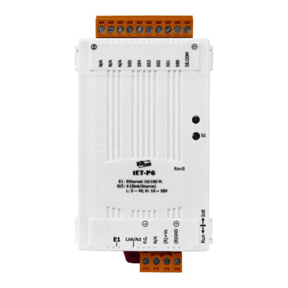
tET-P6, tPET-P6
tET-PD6, tPET-PD6
tET-C4, tPET-C4
tET-A4, tPET-A4
tET-P2C2, tPET-P2C2
tET-P2A2, tPET-P2A2
tET-P2POR2, tPET-P2POR2,
tET-PD2POR2, tPET-PD2POR2
tET-P2R2, tPET-P2R2
tET-PD2R1, tPET-PD2R1
Advertisement
Table of Contents

Related Manuals for ICP DAS USA tET Series


Summary of Contents for ICP DAS USA tET Series
- Page 1 tET/tPET I/O Series User Manual Ethernet I/O Modules Ver.2.4, Sep. 2023 ARRANTY All products manufactured by ICP DAS are warranted against defective materials for a period of one year from the date of delivery to the original purchaser. ARNING ICP DAS assumes no liability for damages consequent to the use of this product.
-
Page 2: Table Of Contents
Ethernet I/O Modules ABLE OF ONTENTS Packing List ............................ 5 More Information .......................... 5 Introduction ........................... 6 1.1 Product Information ......................7 1.1.1 Ethernet IO Module Series ..................7 1.1.2 Selection Guide ......................9 1.1.3 Comparison of tET/tPET Module ................10 1.2 Features .......................... - Page 3 Ethernet I/O Modules Firmware Update via Ethernet ................38 4.4 I/O Settings .......................... 40 4.4.1 Analog Input Configuration ..................40 4.4.2 Calibration ....................... 41 4.4.3 DI/DO Configuration ....................43 4.4.4 DO Control ......................45 4.5 Sync ............................. 46 4.5.1 DIO Synchronization ....................46 4.6 PWM ............................
- Page 4 Ethernet I/O Modules I/O Pair Connection Applications ..................92 5.1 Set a Single Module to Pull/Push Mode (DI/DO) ..............92 5.1.1 Pull Mode ........................ 94 5.1.2 Push Mode ......................95 5.2 Set Two Modules to Push Mode (Local DI to Remote DO) ..........96 5.3 Set Two Modules to PULL Mode (Remote DI to 2-Local DO) ..........
-
Page 5: Packing List
Ethernet I/O Modules Packing List The shipping package includes the following items: tET/tPET Series Module x 1 Quick Start x 1 Note If any of these items are missing or damaged, please contact the local distributor for more information. Save the shipping materials and cartons in case you need to ship the module in the future. -
Page 6: Introduction
Ethernet I/O Modules 1 Introduction The tET/tPET series of devices are Ethernet I/O monitoring and control modules that provide the networking ability and a variety of I/O functions. The modules can be remotely controlled through a 10/100M Ethernet network using the Modbus TCP/UDP protocol. Modbus has become a de facto standard communication, and is now the most commonly available means of connecting industrial electronic devices. -
Page 7: Product Information
Ethernet I/O Modules Product Information 1.1.1 Ethernet IO Module Series The tET/tPET series of Ethernet I/O modules support a range of I/O formats, such as photo-isolated digital input, relay contact, PhotoMOS relay, and open-collector output, etc. The table below provides a description of each model. DC Analog Input tET-AD2 Tiny Ethernet module with 2-ch Isolated AI... - Page 8 Ethernet I/O Modules DC Digital Input and Output tET-P2C2 Tiny Ethernet Module with 2-ch DI and 2-ch (Sink-type, NPN) DO tET-P2A2 Tiny Ethernet Module with 2-ch DI and 2-ch (Source-type, PNP) DO tPET-P2C2 Tiny PoE Ethernet Module with 2-ch DI and 2-ch (Sink-type, NPN) DO tPET-P2A2 Tiny PoE Ethernet Module with 2-ch DI and 2-ch (Source-type, PNP) DO Power Relay Output...
-
Page 9: Selection Guide
Ethernet I/O Modules 1.1.2 Selection Guide Modbu Model I/O Specifications SNMP MQTT Ethernet Isolation tET-AD2 tPET- AD2 (Single-end) Model I/O Specifications Modbus MQTT Ethernet Isolation 6-channel tET-P6 tPET-P6 (Wet Contact) 6-channel tET-PD6 tPET-PD6 (Dry Contact) 4-channel tET-C4 tPET-C4 (Sink) 4-channel tET-A4 tPET-A4 (Source) -
Page 10: Comparison Of Tet/Tpet Module
Ethernet I/O Modules 1.1.3 Comparison of tET/tPET Module The tPET series features true IEEE 802.3af-compliant (classification, Class 1) Power over Ethernet (PoE) functions. Now, not only can data be carried through an Ethernet cable, but power can also be provided. This feature makes installation of tPET series modules a straightforward task. Imagine no more unnecessary wires with only an Ethernet cable required in order to take care of everything in the field. - Page 11 +/- 0.5 kV Form Factor Tiny Size Palm Size Remarks Cost-effective Note: The tET series and tPET series are similar, but only the tPET series has PoE functionality. ICP DAS CO., LTD. tET/tPET IO Series User Manual, Ver. 2.4, Sep. 2023, P11...
-
Page 12: Features
Ethernet I/O Modules Features Built-in Web Server The tET/tPET series module can receive/send network packets efficiently by using a 32-bit MCU. Web Server is also built in to provide an intuitive web management interface that allows users to easily configure, monitor and control the module from a remote location using a web browser. - Page 13 Ethernet I/O Modules Built-in Multi-Function I/O The DO modules support these functions: Power-on Value: On boot up, the DO value will be set to the Power-on value. Safe Value: If Modbus TCP communication is lost for a specific period, the DO value will be set to the user-defined safe value.
- Page 14 Ethernet I/O Modules Built-in Dual Watchdog The Dual Watchdog function consists of a CPU Watchdog (for hardware functions) and a Host Watchdog (for software functions). CPU Watchdog: The CPU Watchdog will automatically reset it-self if the built-in firmware encounters an abnormal situation. Host Watchdog If there is no communication between the module and the host (PC or PLC) for a specified period of time (i.e., the Watchdog timeout), the Host Watchdog will set the digital output based on a...
-
Page 15: Hardware Information
2 Hardware Information Appearance The components of the tET/tPET module include LED indicators, pluggable terminal blocks for power input or I/O, an operating mode switch, and an Ethernet port. tET series tPET series System LED Indicator Operating Mode Switch Power Input Connector... - Page 16 Ethernet I/O Modules System LED Indicator Once power is supplied to the tET/tPET series module, the LED indicator will be illuminated as follows: Function System running Red light (flashing once every 3 seconds) Firmware update in progress (0 ~ 100%) Red light (ON) ...
- Page 17 Ethernet I/O Modules I/O Connector The pin assignments for the I/O connector on the tET/tPET series module differ based on the model. For more information about pin assignments, refer to Section 2.2 “Specification and Wiring”. Operating Mode Switch The operating mode switch on the tET/tPET series module is set to the Run position by default.
-
Page 18: Specification And Wiring
Ethernet I/O Modules Specification and Wiring 2.2.1 Product Page The user can find out the product page on the website (https://www.icpdas.com/) by entering the model in the search bar. 2.2.2 tET/tPET Selection Guide https://www.icpdas.com/en/product/guide+Remote__I_O__Module__and__Unit+Ethernet__I_O_ _Modules+tET_tPET__Series#1110 ICP DAS CO., LTD. tET/tPET IO Series User Manual, Ver. 2.4, Sep. 2023, P18... -
Page 19: Data Sheet
Ethernet I/O Modules 2.2.3 Data Sheet Users can also click the "Data Sheet" icon on the product webpage to view the pin assignments and wire connections. The table listed the web link of the data sheet for tET/tPET series modules. www.icpdas.com/web/product/download/io_and_unit/ethernet/tet_tpet/document/data_sheet/ XXX.pdf 型號... -
Page 20: Dimensions
Ethernet I/O Modules Dimensions The dimensions of tET/tPET series are in millimeters. Front View Rear View Top View Bottom View Left Side View Right Side View ICP DAS CO., LTD. tET/tPET IO Series User Manual, Ver. 2.4, Sep. 2023, P20... -
Page 21: Getting Started
Ethernet I/O Modules 3 Getting Started This chapter provides a basic overview of how to install, configure and operate your tET/tPET series module. Mounting the Module The tET/tPET series module can be mounted by attaching the back of the chassis to a standard 35 mm DIN-Rail. - Page 22 Ethernet I/O Modules Mountable DIN-Rail Models Din-Rail mounts are available in three sizes, and enable a variety of ICP DAS devices to be mounted. Each is made of stainless steel and has a ground wire attached at one end. Maximum Number Part Number Dimensions of Modules...
-
Page 23: Configuring The Operating Mode
Ethernet I/O Modules Configuring the Operating Mode All tET/tPET series modules feature two operating modes, which can be selected by adjusting the switch on the module. Note that it is necessary to reboot the module after modifying the operating mode. ... -
Page 24: Connecting To The Network And The Pc
Ethernet I/O Modules Connecting to the Network and the PC All tET/tPET series module are equipped with an RJ-45 Ethernet port to allow connecting to an Ethernet switch/hub or a PC. Uses Non-PoE Switch Uses PoE Switch (for tPET only) ICP DAS CO., LTD. -
Page 25: Using The Esearch Utility To Assign A New Ip
Ethernet I/O Modules Using the eSearch Utility to Assign a New IP The eSearch Utility is a useful tool that provides a quick and easy method of configuring the Ethernet settings for tET/tPET series module from a PC. Step 1: Download and install the eSearch Utility, and then open the eSearch Utility eSearch Utility can be obtained from the ICP DAS web site at: https://www.icpdas.com/en/download/show.php?num=1327 Step 2: Click the “Search Server”... - Page 26 Ethernet I/O Modules Step 3: Double-click the model name to open the server configuration dialog The default IP address of the module may not be suitable for your network environment, so you need to set a new IP address. The factory preset IP settings are as follows: IP Address: 192.168.255.1 Subnet Mask: 255.255.0.0 Gateway: 192.168.0.1.
- Page 27 Ethernet I/O Modules Step 5: Search the module again and check the settings Click the “Search Server” button to search the module again and check the settings are correct. ICP DAS CO., LTD. tET/tPET IO Series User Manual, Ver. 2.4, Sep. 2023, P27...
-
Page 28: Web Configuration
Ethernet I/O Modules 4 Web Configuration The Ethernet I/O module has a built-in Web Server to provide an intuitive web management interface, allowing users to modify the module’s settings by using a web browser. Logging in to the Web Server After completing the network settings, users can access the module's built-in web server from any computer that's connected to the same network. - Page 29 Ethernet I/O Modules Step 3: Enter the password For the first time to log into the web interface, the default password must be changed. Enter the factory preset password “Admin” and give a new password. Then, click the “Submit” button. The Default Password: Admin Enter the new password in the “Login password”...
- Page 30 Ethernet I/O Modules Step 4: Login to the web server After logging into the module’s web server, the Home page will be displayed. The function tabs will be different depending on the I/O type of the module. For example, Analog Input Digital Input &...
-
Page 31: Home
Ethernet I/O Modules Home The Home page provides users with information about the I/O module, as detailed below. 4.2.1 Module Information The first section offers information about the module, including the model, alias, firmware version, MAC address, the module's IP address, the operating mode switch (Init = OFF), and Watchdog timeouts. -
Page 32: I/O Information
Ethernet I/O Modules 4.2.2 I/O Information The second section allows users to view the status of I/O and Pair-Connection. Furthermore, users have the option to click specific buttons to reset Alarm and Latch statuses or to control the Analog Input Digital Input &... -
Page 33: Network
Ethernet I/O Modules Network The Network page offers three sections, which will be described in the following chapters: 1. IP Address: Used to configure the network IP, Gateway, and MAC addresses for the module. 2. General Settings: Used to configure network settings such as the Ethernet speed, system timeout, TCP timeout, etc. - Page 34 Ethernet I/O Modules The following table provides parameter notes for the IP Address section: Item Description IPv4 Address Static IP: If there is no DHCP server, you can manually assign a static IP address to the module. See “Manual Configuration” section for details.
-
Page 35: Dynamic Configuration
Ethernet I/O Modules Dynamic Configuration If a DHCP server is present on your network, you can dynamically configure a network address using the following procedure: Step 1: Select “DHCP” from the Address Type drop-down menu. Step 2: Click the “Update Settings” button to complete the configuration. Manual Configuration When using manual configuration, the network settings should be assigned in the following manner:... -
Page 36: General Settings
Ethernet I/O Modules 4.3.2 General Settings The following table provides parameter notes for the General Settings section: Item Description Used to set the Ethernet speed. The default value is Auto (10/100 Mbps Ethernet Speed Auto-negotiation). Used to set the system timeout value. If there is no activity on the System Timeout network for a certain period of time, the system will be rebooted based (Network Watchdog) -
Page 37: Restore Factory Defaults, Firmware Update & Reboot
Ethernet I/O Modules 4.3.3 Restore Factory Defaults, Firmware Update & Reboot Restore all options to their factory default states To restore all parameters of the module to their factory presets, follow the steps: Step 1: Click the “Restore Defaults” button to reset the configuration. Step 2: Click the “OK”... -
Page 38: Reboot The Module
Ethernet I/O Modules Reboot the module The Reboot function can be used to remotely force the module to reboot. After that, enter the password to log into the main page. Firmware Update via Ethernet When updating the firmware, the module requires initialization on the LAN. In the case of earlier firmware updates, users had to manually set the operating switch to "Init"... - Page 39 Ethernet I/O Modules 2. Run eSearch Utility to search the module and execute “Firmware Update” to start the process. After completing the initialization, it will start updating. 3. On the module's web interface, click the "Update" button to reboot the module and then start updating.
-
Page 40: I/O Settings
Ethernet I/O Modules I/O Settings The I/O Settings page offers sections such as Analog Input Configuration, Calibration, DI/DO Configuration, DO Control, and more, based on the I/O type. These sections enable users to configure I/O or calibration parameters. Each of these features is described as follows. 4.4.1 Analog Input Configuration The following table provides parameter notes for the Analog Input Configuration section: Item... -
Page 41: Calibration
Ethernet I/O Modules 4.4.2 Calibration The following table provides parameter notes for the Calibration section: Item Description Calibration Now Mode Used to display the current mode Change Mode Click the Calibration Mode (or Run Mode) button to change the mode Channel Choose the AI channel for calibration Item... - Page 42 Ethernet I/O Modules Step2: In the Calibration section of the I/O Settings page, click the Calibration Mode button to get into the calibration mode. Run / Calibration Calibration / Run Mode Step3: Choose a channel for calibration and link the module to a voltage source (or current source) and a multimeter.
-
Page 43: Di/Do Configuration
Ethernet I/O Modules 4.4.3 DI/DO Configuration The following table provides parameter notes for the DI/DO Configuration section: Item Description Digital Output Used to configure the Host Watchdog timeout value. If there is no Host/Slave Watchdog Modbus TCP communication activity for the specified period (the Timeout timeout), then the Host Watchdog will activate an alarm. - Page 44 Ethernet I/O Modules Used to define the DO safe value for the module. If the Host Watchdog Safe Value alarm is activated, the DO will be set to the user-defined safe value. Used to define the DO Power-on value. On boot up, the DO is set to the Power-On Value user-defined Power-on value.
-
Page 45: Do Control
Ethernet I/O Modules 1 ==> No Average is used 2 ==>Uses the average of 2 continuous sample values Moving Average 4 ==>Uses the average of 4 continuous sample values 8 ==>Uses the average of 8 continuous sample values Universal DIO Dynamic: Dynamic I/O types based on DO request. -
Page 46: Sync
Ethernet I/O Modules Sync On the Sync page, the DIO Synchronization section enables users to synchronize DI/DO signals, set the minimum DO switching time, and specify the DO auto-off time on the module. Each of these features will be described in more detail below. 4.5.1 DIO Synchronization ICP DAS CO., LTD. - Page 47 Ethernet I/O Modules The following table provides parameter notes for the DIO Synchronization section: Item Description Synchronous DIO (Local Mirror) Used to enable DIO synchronization function (DO and DI Level Sync (DO = DI) synchronization). Used to enable rising active in Digital Input function. When the Rising Active (DO = ON) specified DI state changed from OFF to ON, the corresponding DO will be set to ON.
-
Page 48: Pwm
Ethernet I/O Modules On the PWM page, the PWM Configuration section allows users to enable and configure the PWM parameters for the DO module. The details are as follows. Note: The module with Relay functionality (see Product Information) is not suitable for prolonged use of PWM (Pulse Width Modulation) due to its inherent characteristics 4.6.1 PWM Configuration The following table provides parameter notes for the PWM Configuration section:... -
Page 49: Mqtt
Ethernet I/O Modules MQTT AI Module DI/DO Module The MQTT architecture mainly consists of a server (Broker) and clients (Clients). Each MQTT Client requires a unique identifier, and the MQTT Broker identifies users based on these identifiers and records their status, such as subscribed topics and communication quality. Clicking on the MQTT tab opens the MQTT settings page. -
Page 50: Connectivity Settings
Ethernet I/O Modules 4.7.1 Connectivity Settings The following table provides parameter notes for the Connectivity Settings section: Item Description Defaults MQTT Enables or Disables the MQTT connection function. Disabled Broker The IP address or the Hostname for the MQTT broker. Broker Port The port number for the MQTT broker. -
Page 51: Publication Settings
Ethernet I/O Modules Item Description Defaults The keep-alive mechanism is provided to ensure that both the client and the broker are alive and the connection is still open. If a Client doesn’t send any messages during the Keep Alive period, it Keep Alive must send a PINGREQ packet to the broker to confirm its availability. - Page 52 Ethernet I/O Modules The following table provides parameter notes for the Publication Settings section: Item Description Defaults Publication Check this option to ensure that the message is retained Retain Disabled once it is published. The time interval that the module periodically publishes Cycle data.
-
Page 53: Analog Inputs
Ethernet I/O Modules 4.7.3 Analog Inputs The following table provides parameter notes for the Analog Inputs section: Item Description Defaults Analog Input To enable or disable the Periodic Publish function. The Periodic publishing period depends on the Cycle settings. Check the Disabled Publish box to enable and uncheck it to disable the function... -
Page 54: Mqtt- Realization
Ethernet I/O Modules MQTT- Realization This section described how to use the open-source software Mosquitto and MQTTX to demonstrate the usage of MQTT protocol in conjunction with the tET/tPET series module. 4.8.1 Set up Mosquitto Mosquitto is an open-source software application that allows you to create an MQTT Broker and can be installed on Windows, Mac OS, Linux, etc. - Page 55 Ethernet I/O Modules Step 2 Locate the “mosquitto.exe” file in the default installation path and double-click it to enable the Mosquitto server. When this window is executing, the Broker is enabled. Closing this window will disable the Broker. Why can’t I open “mosquitto.exe” or why does it crash? Once Mosquitto installation is done, the Broker server is automatically activated upon computer boot-up.
- Page 56 Ethernet I/O Modules In the Services application, locate the "Mosquitto Broker" item and double-click the name to open the Properties dialog. Click the Stop button and set the Startup type to Manual. Click OK to save your changes. ICP DAS CO., LTD. tET/tPET IO Series User Manual, Ver.
- Page 57 Ethernet I/O Modules Step 3 Open Windows Port 1883 (the default Port for the MQTT) Open the Advanced Settings section of the Windows Firewall. Add a new rule. Click Inbound Rules and New Rule, and then select the Port option. Click the Next button to continue.
- Page 58 Ethernet I/O Modules Select the TCP option and then select Specific local ports and enter the value 1883. Click the Next button to continue. Select the Allow the connection option and then click the Next button to continue. ICP DAS CO., LTD. tET/tPET IO Series User Manual, Ver.
- Page 59 Ethernet I/O Modules 3.5 Select the Domain checkbox and click the Next button to continue. 3.6 Enter the name of the rule and then click the Finish button to create the rule. Enter the notes if desired. The Name field is customized. It’s for the user to easily identify.
-
Page 60: Mqttx Instructions
Ethernet I/O Modules 4.8.2 MQTTX Instructions MQTTX is an open source, cross-platform MQTT 5.0 desktop client originally developed by EMQ, which can run on macOS, Linux and Windows. Step1 Install MQTTX Download and execute the installation file (V1.9.4) from the MQTTX website (https://mqttx.app/). Step2 Open MQTTX After the installation is complete, MQTTX will be automatically opened, and the user can also double-click the shortcut on the desktop to open the software. - Page 61 Ethernet I/O Modules Step3 Establish a connection 1. Click "+" and then click New Connection to establish a connection. 2. Enter the Broker name and IP address , and then click the Connect button. (Refer to the Connectivity Settings) Enter a name for easy identification Enter the Broker’s IP address or host name Step4 If the connection is available, the green light will be displayed.
-
Page 62: Mqtt - Do Example
Ethernet I/O Modules 4.8.3 MQTT - DO Example The topic name of MQTT is composed of Main Topic Name (e.g., ICPDAS/, refer to Connectivity Settings) and Sub Topic Name (e.g., do_all), which can be set on the MQTT - DO page. The MQTT –... - Page 63 Ethernet I/O Modules Step2 Make sure that the MQTT function has been enabled on the MQTT page, and the Broker’s IP address and the Main Topic Name have been set (refer to Connectivity Settings). Step3 Enter the message (e.g., 0xF) to be published for the "ICPDAS/do_all” topic, and click the button on the right corner to send the message.
-
Page 64: Mqtt Do - Power On Publish
Ethernet I/O Modules Step 4 The user can check whether the DO status is correct on the Home page. The message “0Xf” indicates DO 0-3 = ON, DO 4-7 = OFF MQTT DO – Power on Publish Step1 Make sure that the Mosquitto Broker is enabled, and the MQTTX... - Page 65 Ethernet I/O Modules Step2 Log in to the module's Web Server, and click the Power-on Publish option for the “do_all” on the MQTT - "DO" page to enable the function. After that, click Update to save the changes. Step3 On the I/O Settings page, set the DO power-on value, and then click Update Setting to update the settings.
- Page 66 Ethernet I/O Modules Step4 After the module boots, the DO value will be set to the predefined power-on value. The DO0, DO1 will be set to ON after rebooting the module. In addition, users can check the received DO values in MQTTX. “0x3”...
-
Page 67: Mqtt Do - State Change Publish
Ethernet I/O Modules MQTT DO – State Change Publish Step1 Make sure that the Mosquitto Broker is enabled, and the MQTTX is connected. In this example, the topic is "ICPDAS/rb_all". Add a subscription Enter the topic name ICPDAS/rb_all Step2 Log in to the module's Web Server, and click the State-Change Publish option for the “rb_all”... - Page 68 Ethernet I/O Modules Step3 On the Home page, set the DO0 to DO2 to “ON” in sequence. Step4 The user can verify the received messages within the MQTTX window. It will receive messages with all DO statuses whenever it changes. 0x1: 0000 0001 (DO0 = ON) 0x3: 0000 0011 (DO0, DO1 = ON) 0x7: 0000 0111 (DO0, DO1, DO2 = ON)
-
Page 69: Mqtt Do - Periodic Publish
Ethernet I/O Modules MQTT DO – Periodic Publish Step1 Make sure that the Mosquitto Broker is enabled, and the MQTTX is connected. In this example, the topic is "ICPDAS/rb_all ". Add a subscription Enter the topic name ICPDAS/rb_all Step2 Log in to the module's Web Server, and click the Periodic Publish option for the “rb_all” on the MQTT - "DO"... - Page 70 Ethernet I/O Modules Step3 Go to the MQTT page, set the message publishing cycle (Cycle), and click "Update Setting" to save the changes. Step4 The user can verify the received messages within the MQTTX window. Receiving DO statuses periodically. In this case, Cycle = 9 seconds ICP DAS CO., LTD.
-
Page 71: Mqtt - Di Example
Ethernet I/O Modules 4.8.4 MQTT - DI Example The topic name of MQTT is composed of Main Topic Name (e.g., ICPDAS/, refer to Connectivity Settings) and Sub Topic Name (e.g., di_all), which can be set on the MQTT - DI page. The MQTT –... - Page 72 Ethernet I/O Modules Step2 Make sure that the Mosquitto Broker is enabled, and the MQTTX is connected. In this example, the topic is "ICPDAS/di_all". Add a subscription Enter the topic name ICPDAS/di_all ICP DAS CO., LTD. tET/tPET IO Series User Manual, Ver. 2.4, Sep. 2023, P72...
- Page 73 Ethernet I/O Modules Step3 Changing the external signal causes the DI status to change, and the MQTT message will be sent from the module. The user ca refer to t(P)ET series Quick Start to wire the I/O for testing purposes. https://www.icpdas.com/en/download/show.php?num=2635 t(P)ET-P2R2: When DO0 is set to ‘ON’, DI0 = ON.
-
Page 74: Mqtt Di - Periodic Publish
Ethernet I/O Modules MQTT DI – Periodic Publish Step 1 Make sure that the Mosquitto Broker is enabled, and the MQTTX is connected. In this example, the topic is "ICPDAS/di_all". Add a subscription Enter the topic name ICPDAS/di_all ICP DAS CO., LTD. tET/tPET IO Series User Manual, Ver. - Page 75 Ethernet I/O Modules Step2 Log in to the module's Web Server, and click the Periodic Publish option for the “di_all” on the MQTT - "DI" page to enable the function. After that, click Update to save the changes. Step3 Go to the MQTT page, set the message publishing cycle (Cycle), and click "Update...
- Page 76 Ethernet I/O Modules Step 4 The user can verify the received messages within the MQTTX window. It will receive periodic messages containing all DI statuses. The Cycle is set to 9 seconds in this case. 0x1: 0000 0001 (DO0 = ON) 0x0: 0000 0000 (OFF) ICP DAS CO., LTD.
-
Page 77: Snmp
Ethernet I/O Modules SNMP The "SNMP" page provides the function for the module to send module information and I/O information to the SNMP Network Management Software or device to help administrators to monitor the status of the module in real time. If the Trap function is enabled, the module can actively send messages to the SNMP manager to keep track of data when the I/O status of the module changes or restarts. - Page 78 Ethernet I/O Modules Item Description Defaults Function Read-Only Community Set the community name of the module for read-only data public Read-Write Community Set the community name of the module for read-write data private Trap Community Set the community name of the module for the trap public Manager / Trap IP #1 Set the IP address of Trap IP #1...
-
Page 79: Snmp I/O Example
Ethernet I/O Modules 4.9.2 SNMP I/O Example In this article, we use iReasoning MIB Browser as an example. Please download the installer (V14) from its official website and run the installer. http://www.ireasoning.com/mibbrowser.shtml Step 1 Start the iReasoning MIB Browser. Click the File > Load MIBs on the menu bar and click the MIB file of the module (e.g. - Page 80 Ethernet I/O Modules Step 3 Click “Advanced…” to set the parameters of the SNMP agent. Enter the string in the Read/Write Community fields according to the Read-Only Community / Read-Write Community settings of the module. If these strings are different on both sides, the agent will not work correctly.
- Page 81 Ethernet I/O Modules Read the information of the tET/tPET – the Walk command To do: Right-click the iso.org.dod. internet folder on the left side and click Walk to display the information of the tET/tPET in the Result Table. The information on analog input of the module.
-
Page 82: Snmp Trap Example
Ethernet I/O Modules 4.9.3 SNMP Trap Example Step 1 Click Tools Trap Receiver on the menu bar to display the window for receiving the Trap messages. Step 2 The types of traps received from the module for alarms are as follows: 1. - Page 83 Ethernet I/O Modules Specific Trap (I/O State-Change): After enabling the specified I/O channel, if the I/O data changes (e.g., ON/OFF or value change), a Trap message with a Specific ID, source IP, and time will be sent. This makes it easier to analyze the cause of the alarm and handle it appropriately.
-
Page 84: Snmp Problem Solving
Ethernet I/O Modules 4.9.4 SNMP Problem Solving Unable to receive the Trap message from the device 1. Check the setting of the Windows firewall or the Anti-virus software. These functions can be disabled during the testing. 2. Check the setting of the Trap port. Using iReasoning MIB Browser as an example, click the Trap Receiver Settings button on the Trap Receiver page to open the window. - Page 85 Ethernet I/O Modules Step 2 Double-click the Services icon. Step 3 Double-click the SNMP Trap and confirm the Startup type is set to “Disabled” and the Service status is set to “Stopped”. ICP DAS CO., LTD. tET/tPET IO Series User Manual, Ver. 2.4, Sep. 2023, P85...
-
Page 86: Pair Connection
Ethernet I/O Modules 4.10 Pair Connection On the Pair page, within the Pair Connection Settings section, users can enable and configure the pair-connection function of the I/O module using Modbus TCP. This allows for the establishment of logic connections between Local and remote I/O, as explained below. 4.10.1 Pair-Connection Settings Note: The configuration page varies based on the I/O type. - Page 87 Ethernet I/O Modules The following table provides parameter notes for the Pair-Connection Settings section: Item Description Defaults Used to enable or disable the Client (Master) function and select either PULL or PUSH mode. PULL Mode: Enable Mode Disable To read the remote AI (or DI) and write to the local AO (or DO). PUSH Mode: To read the local AI (or DI) and write to the remote AO (or DO).
-
Page 88: Filter
Ethernet I/O Modules 4.11 Filter On the Filter page, the Filter Settings section allows users to enable and configure the IP filter list for the module, as explained below. 4.11.1 Filter Settings This function can be used to query or edit the IP filter list for the module. Only Clients whose IP address is specified in the list will be able to access the module. -
Page 89: Monitor
Ethernet I/O Modules 4.12 Monitor On the Monitor page, the Current Connection Status section enables users to observe the real-time status of the network connection for the module ICP DAS CO., LTD. tET/tPET IO Series User Manual, Ver. 2.4, Sep. 2023, P89... -
Page 90: Change Password
Ethernet I/O Modules 4.13 Change Password On the Password page, the Change Password section enables users to modify the login password for the module's web server. The steps are outlined below. Step1: Enter your old password in the the Current password field. When initially logging into the web server, the user is required to change the factory default password (Admin). -
Page 91: Logout
Ethernet I/O Modules 4.14 Logout Click on the Logout tab to sign out from the module's web server and return to the login page. ICP DAS CO., LTD. tET/tPET IO Series User Manual, Ver. 2.4, Sep. 2023, P91... -
Page 92: O Pair Connection Applications
Ethernet I/O Modules 5 I/O Pair Connection Applications The tET/tPET series modules can establish remote logical I/O connections via Ethernet. After configuring the settings, it becomes possible to continuously read the DI status of the local (or remote) module and then write it to the DO of the remote (or local) module. This function is useful when connecting DI/DO modules that have no Ethernet functionality. - Page 93 Ethernet I/O Modules Step 2: Configure the Ethernet Settings Contact your network administrator to get the correct network configuration information (e.g., IP/Mask/Gateway) needed to set up I/O modules. For more instructions, refer to Section 3.4 “Using the eSearch Utility to assign a new IP” ...
-
Page 94: Pull Mode
Ethernet I/O Modules 3. Click the “Pair” tab to display the configuration page. 5.1.1 Pull Mode 1. In the Pair-Connection Setting section, choose PULL and check the box in the Enable Mode field to enable this mode. 2. In the Remote IP… : Port fields, enter the IP address and TCP Port of the remote t(P)ET #2 module. -
Page 95: Push Mode
Ethernet I/O Modules 5.1.2 Push Mode 1. In the Pair-Connection Setting section, choose PUSH and check the box in the Enable Mode field to enable this mode. 2. In the Remote IP… : Port fields, enter the IP address and the TCP Port of the remote t(P)ET #2 module 3. -
Page 96: Set Two Modules To Push Mode (Local Di To Remote Do)
Ethernet I/O Modules Set Two Modules to Push Mode (Local DI to Remote DO) Step 1: Connect the Module to the Network, PC, and Power Supply Confirm that the tET/tPET series modules are functioning correctly. Refer to Chapter 3. “Getting Started”... - Page 97 Ethernet I/O Modules Step 4-1: Configure the Pair-Connection for the tET/tPET #1 (Push Mode) 1. Click the Pair tab to display the configuration page. 2. In the Pair-Connection Setting section, choose PUSH and check the box in the Enable Mode field to enable this mode.
- Page 98 Ethernet I/O Modules Step 4-2: Configure the Pair-Connection for the tET/tPET #2 (Push Mode) 1. Click the Pair tab to display the configuration page. 2. In the Pair-Connection Setting section, choose PUSH and check the box in the Enable Mode field to enable this mode.
-
Page 99: Set Two Modules To Pull Mode (Remote Di To 2-Local Do)
Ethernet I/O Modules Set Two Modules to PULL Mode (Remote DI to 2-Local DO) Step 1: Connect the Module to the Network, PC, and Power Supply Confirm that the tET/tPET series modules are functioning correctly. Refer to Chapter 3. “Getting Started”... - Page 100 Ethernet I/O Modules Step 4-1: Configure the Pair-Connection for the tET/tPET #1 (Pull Mode) 1. Click the Pair tab to display the configuration page. 2. In the Pair-Connection Setting section, choose PULL and check the box in the Enable Mode field to enable this mode.
- Page 101 Ethernet I/O Modules Step 4-2: Configure the Pair-Connection for the tET/tPET #2 (Pull Mode) 1. Click the Pair tab to display the configuration page. 2. In the Pair-Connection Setting section, choose PULL and check the box in the Enable Mode field to enable this mode.
-
Page 102: Set Two Modules To Push Mode (2-Local Di To Remote Do)
Ethernet I/O Modules Set Two Modules to Push Mode (2-Local DI to Remote DO) Step 1: Connect the Module to the Network, PC, and Power Supply Confirm that the tET/tPET series modules are functioning correctly. Refer to Chapter 3. “Getting Started”... - Page 103 Ethernet I/O Modules Step 4-1: Configure the Pair-Connection for the tET/tPET #1 (Push Mode) 1. Click the Pair tab to display the configuration page. 2. In the Pair-Connection Setting section, choose PUSH and check the box in the Enable Mode field to enable this mode.
- Page 104 Ethernet I/O Modules Step 4-2: Configure the Pair-Connection for the tET/tPET #2 (Push Mode) 1. Click the Pair tab to display the configuration page. 2. In the Pair-Connection Setting section, choose PUSH and check the box in the Enable Mode field to enable this mode.
-
Page 105: Shared Memory
Ethernet I/O Modules Shared Memory The tET/tPET DIO series add a 512-byte shared memory which can be used as a tiny data concentrator to store both the AIO and DIO data (256 Registers or 4096-bit shared single memory). Shared memory used with the Pair-Connection function can effectively lower the host load. It can also perform Bits/Registers data exchange, i.e., read data from the remote device and store them in the memory or output signals from the memory to the remote device. -
Page 106: Address Mapping For Shared Memory
Ethernet I/O Modules 5.5.1 Address Mapping for Shared Memory Note: All DI, DO, AI, and AO signals shared a single memory space. The storage address starts at 3000. Writing 16 bits of DI/DO data to addresses 3000 – 3015 is equivalent to writing one 16-bit AI/AO register to the address 3000. -
Page 107: Application Of Spreading The Load
Ethernet I/O Modules 5.5.2 Application of Spreading the Load Original structure New Resolution Overloaded Spread the load Modbus TCP * 9 Modbus TCP * 1 tET/tPET + tET/tPET (DO) Concentrator (DO) 10.0.8.100 10.0.8.200 10.0.8.10 (DI) Device#1 (DI) 10.0.8.10 10.0.8.11 (DI) 10.0.8.12 (DI) Device#8 (DI) 10.0.8.13 (DI) - Page 108 Ethernet I/O Modules Remote IP IO Address Host tET/tPET + Concentrator (Slave #1-8 ) (Shared Memory) 10.0.8.10 3000…3015 10.0.8.11 3016…3031 10.0.8.12 3032…3047 10.0.8.200 10.0.8.13 3048…3063 10.0.8.14 3064…3079 10.0.8.15 3080…3095 10.0.8.16 3096…3111 10.0.8.17 3112…3127 Refer to Chapter 5 - I/O Pair Connection Application for detailed configuration 1.
-
Page 109: Master/Slave/Mtcp/Mudp Data Exchange
Ethernet I/O Modules 5.5.3 Master/Slave/MTCP/MUDP Data Exchange 1. Two hosts can exchange data via shared memory. 2. With the Pair-connection function, two Slave devices can also exchange data via shared memory. 3. With the Pair-connection function, the host can indirectly control the Slave device via the shared memory. -
Page 110: Bits / Registers Data Exchange
Ethernet I/O Modules 5.5.4 Bits / Registers Data Exchange Register Address: Bit Address: 3000 3000 - 3015 < Inquiry for data concentrator > < Master#1 diagram > < Master#2 diagram > Generally, the device cannot exchange the Bit and Register data directly, but this can achieve by using the shared memory of tET/tPET as a concentrator. -
Page 111: Modbus Information
Ethernet I/O Modules Modbus Information The tET/tPET series is a family of IP-based Modbus I/O devices that allow you to remotely control DI/DO terminals via an Ethernet connection and uses a master-slave communication technique in which only one device (the master) can initiate a transaction (called queries), while other devices (slaves) respond by either supplying the requested data to the master, or by taking the action requested in the query. -
Page 112: What Is Modbus Tcp/Ip
Ethernet I/O Modules What is Modbus TCP/IP? Modbus is a communication protocol that was developed by Modicon Inc. in 1979, and was originally designed for use with Modicon controllers. Detailed information regarding the Modbus protocol can be found at: http://www.modbus.org. The different versions of the Modbus protocol used today include Modbus RTU, which is based on serial communication interfaces such as RS-485 and RS-232, Modbus ASCII and Modbus TCP, which uses the Modbus RTU protocol embedded into TCP packets. - Page 113 Ethernet I/O Modules The Leading 6 bytes of a Modbus/TCP Protocol Query Byte 00 Byte 01 Byte 02 Byte 03 Byte 04 Byte 05 Length Field Length Field Transaction identifier Protocol identifier (upper byte ) (lower byte) 1) Transaction identifier = Assigned by the Modbus/TCP Master (Client) 2) Protocol identifier = 0 3) Length field (upper byte) = 0 (since all messages are smaller than 256) 4) Length field (lower byte) = The number of following RTU data bytes...
- Page 114 Ethernet I/O Modules 1) Net ID (Station Number) The first byte in the frame structure of a Modbus RTU query is the receiver’s address. Availed address is in the range of 0 to 247. Address 0 is used for general broadcast, while addresses 1 to 247 are given to individual Modbus devices.
- Page 115 Ethernet I/O Modules 3) Data Field Data is transmitted in 8-, 16- and 32-bit format. The data for 16-bit registers is transmitted in high-byte first format. For example: 0x0A0B ==> 0x0A, 0x0B. The data for 32-bit registers is transmitted as two 16-bit registers, and is low-word first. For example: 0x0A0B0C0D ==> 0x0C, 0x0D, 0x0A, 0x0B.
-
Page 116: 0X01) Read The Status Of The Coils (Readback Dos)
Ethernet I/O Modules 6.2.1 01(0x01) Read the Status of the Coils (Readback DOs) This function code is used to read either the current status of the coils or the current digital output readback value from the tET/tPET module. [Request] Byte Description Size Value... - Page 117 Ethernet I/O Modules Example: Function 01 (0x01), Readback DOs Reads the output value digital [Leading 6 bytes] [Request] Command: 01 02 00 00 00 06 01 01 00 00 00 02 [Leading 6 bytes] [Response] Response: 01 02 00 00 00 04 01 01 01 03 Here is the comprehensive explanation of Modbus Commands and Responses: [Leading 6 bytes]...
-
Page 118: 0X02) Read The Status Of The Input (Read Dis)
Ethernet I/O Modules 6.2.2 02(0x02) Read the Status of the Input (Read DIs) This function code is used to read the current digital input value. [Request] Byte Description Size Value Net ID 1 to 247 Function Code 0x02 Refer to the Modbus Address Table. - Page 119 Ethernet I/O Modules Example: Function 02 (0x02), Read DIs Reads the digital input value [Leading 6 bytes] [Request] Command: 01 02 00 00 00 06 01 02 00 00 00 02 [Leading 6 bytes] [Response] Response: 01 02 00 00 00 04 01 02 01 03 Here is the comprehensive explanation of Modbus Commands and Responses: [Leading 6 bytes]...
-
Page 120: 0X03) Read The Holding Registers (Readback Aos)
Ethernet I/O Modules 6.2.3 03(0x03) Read the Holding Registers (Readback AOs) This function code is used to readback either the current values in the holding registers or the analog output value from the tET/tPET module. These registers are also used to store the preset values for the digital counter, the host watchdog timer, the module name and the TCP timeout, etc. - Page 121 Ethernet I/O Modules Example: Function 03 (0x03), Read AOs Reads the name of the module for the tPET-P2A2. [Leading 6 bytes] [Request] Command: 01 02 00 00 00 06 01 03 01 03 00 02 [Leading 6 bytes] [Response] Response: 01 02 00 00 00 07 01 03 0450 32 41 32 Here is the comprehensive explanation of Modbus Commands and Responses:...
-
Page 122: 0X04) Read The Input Registers (Read Ais)
Ethernet I/O Modules 6.2.4 04(0x04) Read the Input Registers (Read AIs) This function code is used to read either the input registers or the current analog input value from the tET/tPET module. These registers are also used to store the current value for the digital counter, the number of DI channels and the number of DO channels, etc. - Page 123 Ethernet I/O Modules Example: Function 04 (0x04), Read AIs Reads the number of the DI channels on the tPET-P2A2. [Leading 6 bytes] [Request] Command: 01 02 00 00 00 06 01 04 00 64 00 01 [Leading 6 bytes] [Response] Response: 01 02 00 00 00 05 01 04 02 00 02...
-
Page 124: 0X05) Force A Single Coil (Write Do)
Ethernet I/O Modules 6.2.5 05(0x05) Force a Single Coil (Write DO) This function code is used to set the status of a single coil or a single digital output value for the tET/tPET module. [Request] Byte Description Size Value Net ID 1 to 247 Function Code 0x05... - Page 125 Ethernet I/O Modules Example: Function 05 (0x05), Write DO Sets Channel DO1 to ON. [Leading 6 bytes] [Request] Command: 01 02 00 00 00 06 01 05 00 01 FF 00 [Leading 6 bytes] [Response] Response: 01 02 00 00 00 06 01 05 00 01 FF 00 Here is the comprehensive explanation of Modbus Commands and Responses: [Leading 6 bytes]...
-
Page 126: 0X06) Preset A Single Register (Write Ao)
Ethernet I/O Modules 6.2.6 06(0x06) Preset a Single Register (Write AO) This function code is used to set a specific holding register to store the configuration values for the tET/tPET module. [Request] Byte Description Size Value Net ID 1 to 247 Function Code 0x06 Refer to the... - Page 127 Ethernet I/O Modules Example: Function 06 (0x06), Write AO Sets the system timeout to 60 seconds. [Leading 6 bytes] [Request] Command: 01 02 00 00 00 06 01 06 01 08 00 3C [Leading 6 bytes] [Response] Response: 01 02 00 00 00 06 01 06 01 08 00 3C Here is the comprehensive explanation of Modbus Commands and Responses: [Leading 6 bytes]...
-
Page 128: 0X0F) Force Multiple Coils (Write Dos)
Ethernet I/O Modules 6.2.7 15(0x0F) Force Multiple Coils (Write DOs) This function code is used to set multiple coils status or write multiple digital output values for the tET/tPET module. [Request] * Size: Byte Byte Description Size Value Net ID 1 to 247 Function Code 0x0F... - Page 129 Ethernet I/O Modules Example: Function 15 (0x0F), Write Dos Sets the safe value (DO0 – DO1). [Leading 6 bytes] [Request] Command: 01 02 00 00 00 08 01 0F 01 0B 00 02 01 03 [Leading 6 bytes] [Response] Response: 01 02 00 00 00 06 01 0F 01 0B 00 02 Here is the comprehensive explanation of Modbus Commands and Responses:...
-
Page 130: 0X10) Preset Multiple Registers (Write Aos)
Ethernet I/O Modules 6.2.8 16(0x10) Preset Multiple Registers (Write AOs) This function code is used to set multiple holding registers that are used to store the configuration values for the tET/tPET module. [Request] * Size: Byte Byte Description Size Value Net ID 1 to 247 Function Code... - Page 131 Ethernet I/O Modules Example: Function 16 (0x10), Write AOs Sets the Preset value for the digital counter. [Leading 6 bytes] [Request] Command: 01 02 00 00 00 08 01 10 00 32 00 01 02 03 E8 00 00 [Leading 6 bytes] [Response] Response: 01 02 00 00 00 06...
-
Page 132: Modbus Register Table (For Di/Do Module)
Ethernet I/O Modules Modbus Register Table (For DI/DO Module) Data from 16-bit registers is transmitted in high-byte first order. For example: 0x0A0B ==> 0x0A, 0x0B. Data from 32-bit registers is transmitted as two 16-bit registers, and is in low-word first order. For example: 0x0A0B0C0D ==>... - Page 133 Ethernet I/O Modules 4xxxx: AO Address (Base 0) Starting Bits per Access Points Description Range Address Point Type 1 = Reset at Power-on CPU Reset 2 = Reset by the WDT (0xFF) Status Reset using the reset command < 5: Disabled 5 to 65535: Enabled (Units: seconds;...
-
Page 134: Specific Functions
Ethernet I/O Modules 6.3.2 Specific Functions The table below lists the nDI and nDO parameters used in the Modbus address table, representing the number of channels for each tPET series module. Model Name (nDO) (nDI) Number of DO Channels Number of DI Channels Non-PoE tET-P6 tPET-P6... - Page 135 Ethernet I/O Modules Starting Bits per Access Points Description Range Address Point Type 0 = Disable Enables the high and low latches 1 = Enable R/W/F (0x96) for all DI Channels (Default= 0) 0 = Disable Enables the high speed digital 1 to nDI 1 = Enable R/W/F...
- Page 136 Ethernet I/O Modules 3xxxx: AI Address (Base 0) Starting Bits per Access Points Description Value Address Point Type 1 to nDI The Digital Counter Value 0 to 4294967296 (0x10) The frequency Value * 1,000. 1 to nDI (Note: The Client must first 0 to 4294967296 (0x40) divide the value by 1,000.)
- Page 137 Ethernet I/O Modules 4xxxx: AO Address (Base 0) Starting Bits per Access Points Description Range Address Point Type The preset value for the high 1 to nDI 0 to 4294967296 R/W/E (0x32) speed digital counter Note: “Preset DI Counter Value (0x32)” that the records data as 32-bit value and is transmitted as two 16-bit registers.
- Page 138 Ethernet I/O Modules Starting Bits per Access Description Range Points Address Point Type 1= No average Average 2 values 1 to The moving average of the DI R/W/F (0x64) frequency measurement. Average 4 values Average 8 values 1 to The Min-Switching Time for all 1 to 65535 R/W/F (0x10C)
-
Page 139: Modbus Register Table (For Ai Module)
Ethernet I/O Modules 6.4 Modbus Register Table (For AI Module) Coils (0xxxx) Register Factory Points Description Settings Attribute Value 00162 : 00A2 : Clear 1‐ch historical AI max. 1: Clear ‐ 00163 00A3 value 00194 : 00C2 : Clear 1‐ch historical AI min. 1: Clear ‐... - Page 140 Ethernet I/O Modules Register Factory Points Description Settings Attribute Value 00831 033F Zero calibration for the channel 0 1: Set ‐ Span/Gain calibration for the 00832 0340 1: Set ‐ channel 0 ~ 7 Discrete Inputs (1xxxx) Register Points Description Settings Attribute Read AI high alarm status.
- Page 141 Ethernet I/O Modules Holding Register (4xxxx) Register Factory Points Description Data Format Attribute Value Point Set the module 40271 010F identification (Modbus 0 to 255 R/W/E NetID) 40296: 0128: ‐32768 to 32767 32767 Set the AI high alarm value R/W/E 40297 0129 (0x0000 to 0xFFFF)
-
Page 142: Related Tools
Ethernet I/O Modules 7 Related Tools LabVIEW LabVIEW is a system-design platform and development environment and is ideal for acquiring, analyzing, and presenting data. LabVIEW provides graphical development environment that allows you to drag and drop pre-built objects to quickly create data acquisition, instrumentation and control systems, thereby boosting productivity and reducing development time. -
Page 143: Scada
Ethernet I/O Modules SCADA SCADA stands for Supervisor Control and Data Acquisition and is a PC-based production automation and control system. SCADA is widely used in many fields, including power generation, water systems, the oil industry, the chemical, and the automobile industry. Different fields require different functions, but they all have the same common requirements: ... - Page 144 Ethernet I/O Modules InduSoft InduSoft Web Studio is a powerful, integrated collection of automation tools that includes all the building blocks needed to develop modern Human Machine Interfaces (HMI), Supervisory Control and Data Acquisition (SCADA) systems, and embedded instrumentation and control applications. InduSoft Web Studio’s application runs in native Windows NT, 2000, XP, CE and CE .NET environments and conforms to industry standards such as Microsoft .NET, OPC, DDE, ODBC, XML, and ActiveX.
-
Page 145: Appendix: Troubleshooting
Ethernet I/O Modules Appendix: Troubleshooting A: How can I Factory Reset the Module (Password: Admin)? If the module encounters an anomaly and you cannot access the module's web server for configuration, or if you have forgotten the login password, you can perform a factory reset of the all of your customized module. - Page 146 Ethernet I/O Modules Step 3 Adjust the Init/Run switch back to the "Run" mode and reboot the module. Step 4 Log in to the tET/tPET web server. Enter the factory password "Admin" and specify the new password, and then click the Submit button to save the settings. ICP DAS CO., LTD.
-
Page 147: Revision History
Ethernet I/O Modules Revision History This chapter provides revision history information to this document. The table below shows the revision history. Revision Date Description 1. Remove information about PETL-7060 (Phased out) 2. Add information about tET/tPET-PD2 Sep. 2023 3. Add Section 4.4.2 Calibration (for AI modules) 4.
Need help?
Do you have a question about the tET Series and is the answer not in the manual?
Questions and answers