Table of Contents
Advertisement
Quick Links
PETL/tET/tPET DIO Series
User Manual
Ethernet I/O Modules
All products manufactured by ICP DAS are warranted
W
ARRANTY
against defective materials for a period of one year
from the date of delivery to the original purchaser.
ICP DAS assumes no liability for damages consequent
W
ARNING
to the use of this product. ICP DAS reserves the right to
change this manual at any time without notice. The
information furnished by ICP DAS is believed to be
accurate and reliable. However, no responsibility is
assumed by ICP DAS for its use, nor for any
infringements of patents or other rights of third
parties resulting from its use.
C
Copyright © 2017 by ICP DAS. All rights are reserved.
OPYRIGHT
Names are used for identification only and may be
T
RADEMARK
registered trademarks of their respective companies.
If you have any questions, please feel free to contact us
C
U
ONTACT
S
via email at:
service@icpdas.com, service.icpdas@gmail.com
Ver.2.2.1, Mar. 2018
S
This manual relates to the following modules:
PETL-7060
tET-P6, tPET-P6
tET-PD6, tPET-PD6
tET-C4, tPET-C4
tET-A4, tPET-A4
tET-P2C2, tPET-P2C2
tET-P2A2, tPET-P2A2
tET-P2POR2, tPET-P2POR2,
tET-PD2POR2, tPET-PD2POR2
tET-P2R2, tPET-P2R2
tET-PD2R1, tPET-PD2R1
UPPORT
Advertisement
Table of Contents

Related Manuals for ICP DAS USA PETL Series


Summary of Contents for ICP DAS USA PETL Series
- Page 1 PETL/tET/tPET DIO Series User Manual Ethernet I/O Modules Ver.2.2.1, Mar. 2018 All products manufactured by ICP DAS are warranted ARRANTY against defective materials for a period of one year from the date of delivery to the original purchaser. ICP DAS assumes no liability for damages consequent ARNING to the use of this product.
-
Page 2: Table Of Contents
Ethernet I/O Modules ABLE OF ONTENTS PACKING LIST ................................4 MORE INFORMATION ..............................4 INTRODUCTION ..............................5 RODUCT NFORMATION ............................6 1.1.1 Ethernet IO Module Series ..........................6 1.1.2 Selection Guide ............................. 8 EATURES 1.1.3 Comparison of PETL/tET/tPET Module ......................9 ................................ - Page 3 Ethernet I/O Modules 4.4 I/O S ................................... 55 ETTINGS DO Control ................................55 DI/DO Configuration ..............................56 4.5 S ....................................59 4.6 PWM .................................... 61 DIO Synchronization ..............................59 4.7 P PWM Configuration ..............................61 ....................................63 4.8 F ILTER Pair-Connection Settings ............................
-
Page 4: Packing List
Ethernet I/O Modules Packing List The shipping package includes the following items: tET/tPET Series x 1 Quick Start x 1 Note If any of these items are missing or damaged, please contact the local distributor for more information. Save the shipping materials and cartons in case you need to ship the module in the future. More Information ... -
Page 5: Introduction
Ethernet I/O Modules 1. Introduction The tET/tPET and PETL-7060 series of devices are IP-based Ethernet I/O monitoring and control modules that provide networking ability and a variety of digital I/O functions. The modules can be remotely controlled through a 10/100 M Ethernet network using the Modbus TCP/UDP protocol. Modbus has become a de facto standard communications, and is now the most commonly available means of connecting industrial electronic devices. -
Page 6: Product Information
Ethernet I/O Modules 1.1 Product Information 1.1.1 Ethernet IO Module Series The tET/tPET and PETL-7060 series of Ethernet I/O modules support a range of I/O formats, such as photo-isolated digital input, relay contact, PhotoMOS relay, and open-collector output, etc. The table below provides a description of each model. DC Digital Input tET-P6 Tiny Ethernet module with 6-channel digital input (Wet Contact) - Page 7 Ethernet I/O Modules Power Relay Output Tiny Ethernet module with 2-channel digital input(Wet Contact) and 2-channel tET-P2R2 Form A power relay output Tiny Ethernet module with 2-channel digital input(Dry Contact) and 1-channel tET-PD2R1 Form A power relay output Tiny Ethernet module with PoE, 2-channel digital input(Wet Contact) and tPET-P2R2 2-channel Form A power relay output Tiny Ethernet module with PoE, 2-channel digital input(Dry Contact) and...
-
Page 8: Selection Guide
Ethernet I/O Modules 1.1.2 Selection Guide Model I/O Specifications Ethernet Modbus 10/100 M Ethernet D/I (Type) D/O (Type) Isolation 6-channel tET-P6 tPET-P6 (Wet Contact) 6-channel tET-PD6 tPET-PD6 (Dry Contact) 4-channel tET-C4 tPET-C4 (Sink) 4-channel tET-A4 tPET-A4 (Source) 2-channel 2-channel tET-P2C2 tPET-P2C2 (Wet Contact) (Sink) -
Page 9: Comparison Of Petl/Tet/Tpet Module
Ethernet I/O Modules 1.1.3 Comparison of PETL/tET/tPET Module The tPET and PETL-7060 series features true IEEE 802.3af-compliant (classification, Class 1) Power over Ethernet (PoE) functions. Now, not only can data be carried through an Ethernet cable, but power can also be provided. This feature makes installation of tPET series modules a straightforward task. - Page 10 Ethernet I/O Modules More Information All tET series modules can only be powered using a+12 V to +48 V power supply connected through a removable terminal block. In contrast, tPET and PETL-7060 series modules offer two methods of supplying power. The first is through the Ethernet via a PoE switch;...
-
Page 11: Features
Ethernet I/O Modules 1.2 Features Built-in Web Server Each tET/tPET/PETL series module contains a built-in web server that allows users to easily configure, monitor and control the module from a remote location using a web browser. Modbus Protocol The Modbus TCP/UDP slave function on the Ethernet port can be used to provide data to remote SCADA software. - Page 12 “Low Duty Cycle” corresponds to the duration of the 'off' time. Consequently, it is not necessary to keep switching from ON to OFF from remote a controller. In this way, the tET/tPET/PETL series module reduces the complexity required for the control system and enhances timing accuracy.
- Page 13 Ethernet I/O Modules I/O Pair-Connection The I/O Pair-connection function is used to create a digital input to digital output pair through the Ethernet. Once the configuration is complete, the PETL/tET/tPET series modules can continuously poll the status of a remote digital input device using the Modbus TCP protocol, and then write to the local digital output channels in the background.
-
Page 14: Hardware Information
Ethernet I/O Modules 2. Hardware Information 2.1 Front and Back Panel The following is a brief overview and description of the components included in PETL/tET/tPET series modules. PETL-7060 tET/tPET Series Ethernet Port System LED Indicator J1 Connector... -
Page 15: Ethernet Port
Ethernet I/O Modules Ethernet Port The PETL/tET/tPET series module are equipped with an RJ-45 jack that is used as the 10/100 Base-TX Ethernet port and features networking capability. When an Ethernet link is detected and an Ethernet packet is received, the Link/Act LED (Green) indicator and the10/100 M LED (Yellow) indicator will be illuminated. - Page 16 Ethernet I/O Modules Frame Ground: Electronic circuits are constantly vulnerable to Electrostatic Discharge (ESD), which becomes worse in a continental climate area. PETL/tET/tPET series module feature a new design for the frame ground, which provides a path that bypasses ESD, resulting in an enhanced ESD protection capability and ensuring that the module is more reliable.
-
Page 17: Operating Mode Switch
Ethernet I/O Modules Operating Mode Switch Init mode: Uses factory settings and allows the firmware to be updated. Run/Normal mode: Uses customer settings. The operating mode switch for PETL/tET/tPET series modules is set to the Run/Normal position by default. -
Page 18: System Led Indicator
Ethernet I/O Modules System LED Indicator Once power is supplied to the PETL/tET/tPET series module, the LED indicator will be illuminated as follows: tET/tPET Series Function System LED Behavior Running Firmware ON (Red) Network Ready Flashing once every 3 seconds (Red) PoE (for tPET only) ON (Green) PETL-7060... -
Page 19: System Specifications
Ethernet I/O Modules 2.2 Specifications 2.2.1 System Specifications Modules tET Series tPET Series PETL-7060 System 32-bit MCU Dual Watchdog Communication 10/100 Base-TX, 8-Pin RJ-45 x1, Ethernet Port (Auto-negotiating, Auto-MDI/MDIX, LED Indicator) PoE (IEEE 802.3af, Class 1) LED Display PoE Indicator S1 (Green) PoE (Green) System Indicator... -
Page 20: I/O Specifications
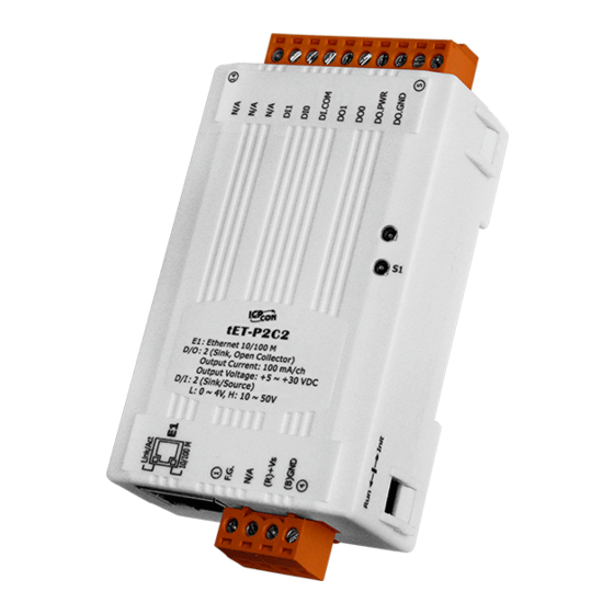
Ethernet I/O Modules 2.2.2 I/O Specifications tET-P6/tPET-P6/tET-PD6/tPET-PD6 tET-P6 tET-PD6 Models tPET-P6 tPET-PD6 Digital Input Input Channels Input Type (Device) Wet Contact (Sink, Source) Dry Contact (Source) On Voltage Level +10 V ~ +50 V Close to GND Off Voltage Level +4 V max. - Page 21 Ethernet I/O Modules tET-P2C2/tPET-P2C2/tET-P2A2/tPET-P2A2 tET-P2C2 tET-P2A2 Models tPET-P2C2 tPET-P2A2 Digital Input Input Channels Input Type (Device) Wet Contact (Sink, Source) On Voltage Level +10 V ~ +50 V Off Voltage Level +4 V Max. Ω Input Impedance 10 k Max. Count: 4,294,967,285 (32 bits) Counters Min.
- Page 22 Ethernet I/O Modules tET-P2POR2/tPET-P2POR2/tET-PD2POR2/tPET-PD2POR2 tET-P2POR2 tET-PD2POR2 Models tPET-P2POR2 tPET-PD2POR2 Digital Input Input Channels Input Type (Device) Wet Contact (Sink, Source) Dry Contact (Source) On Voltage Level +10 V ~ +50 V Close to GND Off Voltage Level +4 V Max. Open Ω...
- Page 23 Ethernet I/O Modules tET-P2R2/tPET-P2R2/tET-PD2R1/tPET-PD2R1 tET-P2R2 tET-PD2R1 Models tPET-P2R2 tPET-PD2R1 Digital Input Input Channels Input Type (Device) Wet Contact (Sink, Source) Dry Contact (Source) On Voltage Level +10 V ~ +50 V Close to GND Off Voltage Level +4 V Max. Open Ω...
- Page 24 Ethernet I/O Modules PETL-7060 Models PETL-7060 Digital Input Input Channels Input Type (Device) Wet Contact (Sink, Source) On Voltage Level +10 V ~ +50 V Off Voltage Level +4 V Max. Ω Input Impedance 10 k Max. Count 4,294,967,285 (32 bits) Counters Min.
-
Page 25: In Assignments
Ethernet I/O Modules 2.3Pin Assignments tET-P6/tPET-P6/tET-PD6/tPET-PD6 : I/O Address Mapping : Counter Address Mapping ICP DAS CO., LTD. PETL/tET/tPET DIO Series User Manual, Ver. 2.2, Aug. 2017, Page: 25... -
Page 26: Tet-C4/Tpet-C4/Tet-A4/Tpet-A4
Ethernet I/O Modules tET-C4/tPET-C4/tET-A4/tPET-A4 : I/O Address Mapping ICP DAS CO., LTD. PETL/tET/tPET DIO Series User Manual, Ver. 2.2, Aug. 2017, Page: 26... -
Page 27: Tet-P2Por2/Tpet-P2Por2/Tet-P2R2/Tpet-P2R2
Ethernet I/O Modules tET-P2POR2/tPET-P2POR2/tET-P2R2/tPET-P2R2 : I/O Address Mapping : Counter Address Mapping ICP DAS CO., LTD. PETL/tET/tPET DIO Series User Manual, Ver. 2.2, Aug. 2017, Page: 27... -
Page 28: Tet-Pd2Por2/Tpet-Pd2Por2
Ethernet I/O Modules tET-PD2POR2/tPET-PD2POR2 : I/O Address Mapping : Counter Address Mapping ICP DAS CO., LTD. PETL/tET/tPET DIO Series User Manual, Ver. 2.2, Aug. 2017, Page: 28... -
Page 29: Tet-Pd2R1/Tpet-Pd2R1
Ethernet I/O Modules tET-PD2R1/tPET-PD2R1 : I/O Address Mapping : Counter Address Mapping ICP DAS CO., LTD. PETL/tET/tPET DIO Series User Manual, Ver. 2.2, Aug. 2017, Page: 29... -
Page 30: Tet-P2C2/Tpet-P2C2/Tet-P2A2/Tpet-P2A2
Ethernet I/O Modules tET-P2C2/tPET-P2C2/tET-P2A2/tPET-P2A2 : I/O Address Mapping : Counter Address Mapping ICP DAS CO., LTD. PETL/tET/tPET DIO Series User Manual, Ver. 2.2, Aug. 2017, Page: 30... -
Page 31: Wpetl-7060
Ethernet I/O Modules PETL-7060 : I/O Address Mapping ICP DAS CO., LTD. PETL/tET/tPET DIO Series User Manual, Ver. 2.2, Aug. 2017, Page: 31... -
Page 32: Input Wiring
Ethernet I/O Modules 2.4 Wiring Connections 2.4.1 Input Wiring tET-P6/ tPET-P6,tET-P2C2/ tPET-P2C2, tET-P2A2/tPET-P2A2,tET-P2POR2/tPET-P2POR2, tET-P2R2 /tPET-P2R2, PETL-7060 Input Type Readback as 1 Readback as 0 + 10 ~ +50 V OPEN or <4 V Sink + 10 ~ +50 V OPEN or <4 V Source ... -
Page 33: Output Wiring
Ethernet I/O Modules 2.4.2 Output Wiring tET-C4/tPET-C4, tET-P2C2/tPET-P2C2 Output Type Readback as 1 Readback as 0 Relay ON Relay OFF Drive Relay Resistance Load tET-A4/tPET-A4, tET-P2A2/tPET-P2A2 Output Type ON State Readback as 1 OFF State Readback as 0 ICP DAS CO., LTD. - Page 34 Ethernet I/O Modules tET-P2R2/tPET-P2R2, tET-PD2R1/tPET-PD2R1, PETL-7060 Output Type Readback as 1 Readback as 0 Relay ON Relay OFF Relay Output tET-P2POR2/tPET-P2POR2, tET-PD2POR2/tPET-PD2POR2 Output Type Readback as 1 Readback as 0 Relay ON Relay OFF Form A Relay Contact ICP DAS CO., LTD.
- Page 35 Ethernet I/O Modules 2.5 Dimensions The PETL-7060 dimensions are in millimeters. Front View Rear View Top View Bottom View Side View Din-Rail Mounting Bracket Side View ICP DAS CO., LTD. PETL/tET/tPET DIO Series User Manual, Ver. 2.2, Aug. 2017, Page: 35...
- Page 36 Ethernet I/O Modules The tET/tPET series dimensions are in millimeters. Front View Rear View Top View Bottom View Left Side View Right Side View ICP DAS CO., LTD. PETL/tET/tPET DIO Series User Manual, Ver. 2.2, Aug. 2017, Page: 36...
-
Page 37: Getting Started
Ethernet I/O Modules 3. Getting Started This chapter provides a basic overview of how to install, configure and operate your PETL/tET/tPET series module. 3.1 Mounting the Module The PETL/tET/tPET series module can be mounted by attaching the bottom of the chassis to a DIN-Rail, or the wall or it can be piggybacked to another module. - Page 38 Ethernet I/O Modules Mountable DIN-Rail Models Din-Rail mounts are available in three sizes, and enable a variety of ICP DAS devices to be mounted. Each is made of stainless steel and has a ground wire attached at one end. Part Number Maximum Number of Modules Dimensions DRS-125...
- Page 39 Ethernet I/O Modules 3.2 Configuring the Boot Mode All PETL/tET/tPET series modules have two operating modes that can be selected by using the switch mechanism incorporated on the chassis. Note that the module must be rebooted after changing the operating mode. Init Mode Init Mode should only be selected when updating the firmware or while troubleshooting.
-
Page 40: Connecting To A Network Apc And A Power Supply 3.4 U
Ethernet I/O Modules 3.3 Connecting to a Network, a PC and a Power Supply All PETL/tET/tPET series module are equipped with an RJ-45 Ethernet port to allow connection to an Ethernet hub/switch or a PC. Uses Non-PoE Switch Uses PoE Switch (for PETL/tPET only) ICP DAS CO., LTD. -
Page 41: Search Utility To Assign A New Ip
Ethernet I/O Modules 3.4 Using the eSearch Utility to Assign a New IP The eSearch Utility is a useful tool that provides a quick and easy method of configuring the Ethernet settings for PETL/tET/tPET series module from a PC. Step 1: Download and install the eSearch Utility software, and open the eSearch Utility eSearch Utility can be obtained either from the companion CD at: CD:\Napdos\Software\eSearch\ Or from the ICP DAS web site at:... - Page 42 Ethernet I/O Modules Step 3: Double-click the name of the module to open the server configuration dialog. All PETL/tET/tPET series modules are IP-based devices that may not be suitable for your network using the default IP address. Therefore, you must first assign a new IP address to the PETL/tET/tPET series module depending on your network settings.
- Page 43 Ethernet I/O Modules Step 5: Wait for 2 seconds and then click the “Search Servers” button again. Ensure that the PETL/tET/tPET series module is operating correctly using the new configuration. ICP DAS CO., LTD. PETL/tET/tPET DIO Series User Manual, Ver. 2.2, Aug. 2017, Page: 43...
-
Page 44: Web Configuration
Ethernet I/O Modules 4. Web Configuration All PETL/tET/tPET series module contain an advanced embedded web configuration system that provides I/O accessibility to the PETL/tET/tPET series module via a web browser. 4.1 Logging in to the Web Server You can access the embedded PETL/tET/tPET series web server from any computer that has an Internet connection. - Page 45 Ethernet I/O Modules Step 3: Enter the password After entering the IP address, the main login dialog page will be displayed prompting you to enter a password. The factory default password is “Admin”. Click the “Submit” button to continue. Factory Default Password: Admin Step 4: Login to the PETL/tET/tPET web server After logging into the PETL/tET/tPET web server, the main page will be displayed.
-
Page 46: Home
Ethernet I/O Modules 4.2 Home The Home link connects to the main page, which contains three parts. The first part of this page provides basic information about the PETL/tET/tPET hardware and software. The software and hardware information section includes information related to the Model Name, the current Firmware version, the IP Address, the current position of the Initial Switch, the Alias, the If you update the firmware for the MAC Address, and the TCP Port, and the System Timeout values. - Page 47 Ethernet I/O Modules The third section provides details related the status of the I/O pair-connections. ICP DAS CO., LTD. PETL/tET/tPET DIO Series User Manual, Ver. 2.2, Aug. 2017, Page: 47...
-
Page 48: Network Settings
Ethernet I/O Modules 4.3 Network Settings Clicking the Network tab will display the IP Address Configuration page allowing you verify the current settings and configure the IP Address parameters, configure the general parameters and restore the default settings for the PETL/tET/tPET series module, each of which will be described in more detail below. - Page 49 Ethernet I/O Modules The following table provides an overview of the parameters contained in the IP Address configuration section: Item Description Static IP: If there is no DHCP server installed in your network, you can configure the network settings manually. Refer to Section “Manual Configuration”...
- Page 50 Ethernet I/O Modules Dynamic Configuration Dynamic configuration is very easy to perform. If a DHCP server is connected to you network, a network address can be dynamically configured by using the following procedure: Step 1: Select “DHCP” from the Address Type drop-down menu. Step 2: Click the “Update Settings”...
-
Page 51: General Settings
Ethernet I/O Modules General Settings The following table provides an overview of the parameters contained in the General Settings section: Item Description This parameter is used to set the Ethernet speed. The default value is Auto Ethernet Speed (Auto = 10/100 Mbps Auto-negotiation). This parameter is used to configure the system timeout value. -
Page 52: Restore Factory Defaults
Ethernet I/O Modules Restore Factory Defaults Restore all options to their factory default states To reset all parameters to their original factory default settings, use the following procedure: Step 1: Click the “Restore Defaults” button to reset the configuration. Step 2: Click the “OK”... - Page 53 Ethernet I/O Modules Forced Reboot The Forced Reboot function: can be used to force the PETL/tET/tPET to reboot or to remotely module reboot for the device. After the PETL/tET/tPET module has rebooted, the original login screen will be displayed requesting that you enter your Login Password before continuing. ICP DAS CO., LTD.
-
Page 54: Firmware Update
Ethernet I/O Modules Firmware Update Firmware update requires initialization and local network operations. Traditional firmware update requires adjusting the Init/Run Switch and reboots the module manually for the initialization of firmware update, while new firmware allows user to initialize the module via web interface without adjusting the hardware switch. -
Page 55: I/O Settings
Ethernet I/O Modules 4.4 I/O Settings Clicking the I/O Settings tab will display the DO Control and DI/DO Configuration page allowing you configure the Digital Input and Digital Output parameters for the PETL/tET/tPET module. This page including Digital Output control, DI/DO Configuration, etc., each of which will be described in more detail below. -
Page 56: Di/Do Configuration
Ethernet I/O Modules DI/DO Configuration The following table provides an overview of the parameters contained in the DI/DO Configuration section: Item Description Digital Output This parameter is used to configure the Host Watchdog timeout value. If there Host/Slave Watchdog is no Modbus TCP communication activity for the specified period (the Timeout timeout), then the Host Watchdog will activate an alarm. - Page 57 Ethernet I/O Modules Digital Input This parameter is uses to enable the latch function on all DI channels. The Enable Latched DI status of the DI will be recorded if it has been flagged as either high or low. 0 = Disable All; 1 = Enable All This parameter is used to clear the status of all high latched D/I.
- Page 58 Ethernet I/O Modules 1 ==> No Average is used 2 ==>Uses the average of 2 continuous sample values Moving Average 4 ==>Uses the average of 4 continuous sample values 8 ==>Uses the average of 8 continuous sample values Universal DIO Dynamic: Dynamic I/O types based on DO request.
-
Page 59: Dio Synchronization
Ethernet I/O Modules 4.5 Sync Clicking the Sync tab will display the DIO Synchronization page allowing you configure the Synchronous DIO, Min-switching time of DO and Auto-off Time of DO for the series PETL/tET/tPET module, each of which will be described in more detail below. DIO Synchronization ICP DAS CO., LTD. - Page 60 Ethernet I/O Modules The following table provides an overview of the parameters contained in the DIO Synchronization section: Item Description Synchronous DIO (Local Mirror) This parameter is used to enable the synchronization operation in Digital Level Sync (DO = DI) Input/Output function.
-
Page 61: S 4.6 Pwm
Ethernet I/O Modules 4.6 PWM Clicking the PWM tab will display the PWM Configuration page allowing you enable and configure the PWM parameters for the PETL/tET/tPET device, including the PWM Alarm and duty cycle, etc., each of which will be described in more detail below. PWM Configuration The following table provides an overview of the parameters contained in the PWM Configuration section:... - Page 62 Ethernet I/O Modules Item Description Default Value This parameter is used to set the duty cycle for the DO channels. Two values are required for each DO channel. The first value is the high pulse width, while the second is the low pulse width.
-
Page 63: Pair-Connection Settings
Ethernet I/O Modules 4.7 Pair Clicking the Pair tab will display the pair-connection Settings page allowing you enable and configure the DI-to-DO pair connections for the PETL/tET/tPET module, which will be described in more detail below. Pair-Connection Settings The I/O pair connection function is a specific feature of the PETL/tET/tPET series modules that can be used to enable a pair of DI-to-DO connections via the Modbus TCP (Ethernet) protocol. - Page 64 Ethernet I/O Modules The following table provides an overview of the parameters contained in the Pair-Connection Settings section: Default Item Description Value This parameter is used to define the Server mode for the PETL/tET/tPET series module. Mode = Disable: Server mode (Slave). Mode Mode = POLL: Poll remote DI to local DO in the Client mode (Master).
- Page 65 Ethernet I/O Modules For “POLL” mode, this parameter specifies the base address of the Local DO register that will be mapped to the Remote DI device. The range depends on the type of the ET-2200 module being used. DO Addr For “PUSH”...
-
Page 66: Filter Settings
Ethernet I/O Modules 4.8 Filter Clicking the Filter tab will display the Filter Settings page allowing you configure the IP Filter list for the PETL/tET/tPET module, which will be described in more detail below. Filter Settings The Filter Settings page is used to query or edit the IP Filter List for the PETL/tET/tPET series module. The IP filter list restricts the access of incoming packets based on the IP header. - Page 67 Ethernet I/O Modules The following table provides an overview of the parameters contained in the IP Address Configuration section: Item Description Add “IP” to the List This parameter is used to add an IP address to the Available IP List. Delete IP # “number”...
-
Page 68: Onitor Hange
Ethernet I/O Modules 4.9 Monitor After clicking the Monitor tab, the Current Connection Status page will be displayed showing detailed information regarding the current status of the serial port connection settings for the PETL/tET/tPET series module. 4.10 Change Password Clicking the Change Password tab will display the Change Password page. To change a password, first enter the old password in the “Current password”... -
Page 69: Ogout
Ethernet I/O Modules 4.11 Logout Clicking the Logout tab will immediately log you out from the system and return you to the login page. ICP DAS CO., LTD. PETL/tET/tPET DIO Series User Manual, Ver. 2.2, Aug. 2017, Page: 69... -
Page 70: I/O Pair Connection Applications
Ethernet I/O Modules 5. I/O Pair Connection Applications The PETL/tET/tPET series modules can be used to create DI-to-DO pair connections via the Ethernet. Once the configuration is complete, the modules can then poll the status of the local DI channels and then use the Modbus/TCP protocol to continuously write to a remote DO device in the background. - Page 71 Ethernet I/O Modules Step 2: Configure the Ethernet Settings Contact your Network Administrator to obtain the correct network configuration information for the PETL/tET/tPET series modules, such as the IP Address, Subnet Mask, and Gateway details. Refer to Section 3.4 “Using the eSearch Utility to assign a new IP” for more details.
-
Page 72: Polling Mode
Ethernet I/O Modules 3. Click the “Pair” tab to display the Pair Connection settings page. Figure 5-1.4 Polling Mode 4. In the “I/O Pair-connection Settings”, select “POLL” from the “Mode” drop-down options. 5. Enter the IP address for tPET-PD2POR2 #2 module in the “Remote IP” field. 6. -
Page 73: Push Mode
Ethernet I/O Modules Push Mode 4. In the “I/O Pair-connection Settings”, select “PUSH” from the “Mode” drop-down options. 5. Enter the IP address for tPET-PD2POR2 #2 module in the “Remote IP” field. 6. Enter the TCP Port for tPET-PD2POR2 #2 module in the “Remote Port” field. 7. - Page 74 Ethernet I/O Modules 5.2 Two Modules Pushing the Local DI to each other (1-to-1, Push mode) Step 1: Connect the device to a Network, a PC and a Power supply. Confirm that the PETL/tET/tPET series modules are functioning correctly. Refer to Chapter 3 “Getting Started”...
- Page 75 Ethernet I/O Modules Step 3: Configure the I/O Pair connection on the tPET-P2POR2 #1 module 1. In the eSearch Utility, select tPET-P2POR2 #1 module and then click the “Web” button to launch the browser program and connect to the web server. 2.
- Page 76 Ethernet I/O Modules Step 4: Configure the I/O Pair connection on the tPET-PD2POR2 #2 module 1. In the eSearch Utility, select tPET-PD2POR2 #2 module and then click the “Web” button to launch the browser program and connect to the web server. 2.
-
Page 77: Ode )
Ethernet I/O Modules 5.3 Several Modules Polling the Remote DI (M-to-1) (Polling Mode) Step 1: Connect the device to a Network, a PC and a Power supply. Confirm that the PETL/tET/tPET series modules and remote slave device are functioning correctly. Refer to Chapter 3 “Getting Started”... - Page 78 Ethernet I/O Modules Step 3: Configure the I/O Pair connection on the tPET-P2POR2 #1 module 1. In the eSearch Utility, select tPET-P2POR2 #1 module and then click the “Web” button to launch the browser program and connect to the web server. 2.
- Page 79 Ethernet I/O Modules Step 4: Configure the I/O Pair connection on the tPET-PD2POR2 #2 module 1. In the eSearch Utility, select tPET-PD2POR2 #2 module and then click the “Web” button to launch the browser program and connect to the web server. 2.
-
Page 80: Everal Odules Ushing The Ocal Ldi (M- To Ush Ode )
Ethernet I/O Modules 5.4 Several Modules Pushing the Local DI (M-to-1) (Push Mode) Step 1: Connect the device to a Network, a PC and a Power supply. Confirm that the PETL/tET/tPET series modules and remote slave device are functioning correctly. Refer to Chapter 3. - Page 81 Ethernet I/O Modules Step 3: Configure the I/O Pair connection on the tPET-P2POR2 #1 module 1. In the eSearch Utility, select tPET-P2POR2 #1 module and then click the “Web” button to launch the browser program and connect to the web server. 2.
- Page 82 Ethernet I/O Modules Step 4: Configure the I/O Pair connection on the tPET-PD2POR2 #2 module 1. In the eSearch Utility, select tPET-PD2POR2 #2 module and then click the “Web” button to launch the browser program and connect to the web server. 2.
-
Page 83: Wmodbus Information
Ethernet I/O Modules Modbus Information The PETL/tET/tPET series is a family of IP-based Modbus I/O devices that allow you to remotely control DI/DO terminals via an Ethernet connection uses master-slave communication technique in which only one device (the master) can initiate a transaction (called queries), while other devices (slaves) respond by either supplying the requested... -
Page 84: Modbus Message Structure
Ethernet I/O Modules 6.1 What is Modbus TCP/IP? Modbus is a communication protocol that was developed by Modicon Inc. in 1979, and was originally designed for use with Modicon controllers. Detailed information regarding the Modbus protocol can be found at: http://www.modbus.org. The different versions of the Modbus protocol used today include Modbus RTU, which is based on serial communication interfaces such as RS-485 and RS-232, Modbus ASCII and Modbus TCP, which uses the Modbus RTU protocol embedded into TCP packets. -
Page 85: Essage
Ethernet I/O Modules The Leading 6 bytes of a Modbus/TCP Protocol Query Byte 00 Byte 01 Byte 02 Byte 03 Byte 04 Byte 05 Length Field Length Field Transaction identifier Protocol identifier (upper byte ) (lower byte) = Assigned by the Modbus/TCP master (client) Transaction identifier Protocol identifier = 0 (since all messages are smaller than 256) - Page 86 Ethernet I/O Modules 1. Net ID (Station Number) The first byte in the frame structure of a Modbus RTU query is the receiver’s address. Availed address is in the range of 0 to 247. Address 0 is used for general broadcast, while addresses 1 to 247 are given to individual Modbus devices.
-
Page 87: Essage
Ethernet I/O Modules 3. Data Field Data is transmitted in 8-, 16- and 32-bit format. The data for 16-bit registers is transmitted in high-byte first format. For example: 0x0A0B ==> 0x0A, 0x0B. The data for 32-bit registers is transmitted as two 16-bit registers, and is low-word first. -
Page 88: 0X01) Read The Status Of The Coils (Readback Dos)
Ethernet I/O Modules 01(0x01) Read the Status of the Coils (Readback DOs) This function code is used to read either the current status of the coils or the current digital output readback value from the PETL/tET/tPET module. [Request] Byte Description Size Value Net ID (Station Number) - Page 89 Ethernet I/O Modules Example: Function 01 (0x01), Readback DOs [Leading 6 bytes] [Request] Command: 01 02 00 00 00 06 01 01 00 00 00 02 [Leading 6 bytes] [Response] Response: 01 02 00 00 00 04 01 01 01 03 Reads the digital output value A description of the command and response is as follows: Command:...
-
Page 90: 0X02) Read The Status Of The Input (Read Dis)
Ethernet I/O Modules 02(0x02) Read the Status of the Input (Read DIs) This function code is used to read the current digital input value from the PETL/tET/tPETL module. [Request] Byte Description Size Value Net ID (Station Number) 1 Byte 1 to 247 Function Code 1 Byte 0x02... - Page 91 Ethernet I/O Modules Example: Function 02 (0x02), Read DIs [Leading 6 bytes] [Request] Command: 01 02 00 00 00 06 01 02 00 00 00 02 [Leading 6 bytes] [Response] Response: 01 02 00 00 00 04 01 02 01 03 Reads the digital input value A description of the command and response is as follows: Command:...
-
Page 92: 0X03) Read The Holding Registers (Readback Aos)
Ethernet I/O Modules 03(0x03) Read the Holding Registers (Readback AOs) This function code is used to readback either the current values in the holding registers or the analog output value from the PETL/tET/tPET module. These registers are also used to store the preset values for the digital counter, the host watchdog timer, the module name and the TCP timeout, etc. - Page 93 Ethernet I/O Modules Example: Function 03 (0x03), Read AOs [Leading 6 bytes] [Request] Command: 01 02 00 00 00 06 01 03 01 03 00 02 [Leading 6 bytes] [Response] Response: 01 02 00 00 00 07 01 03 0450 32 41 32 Reads the name of the module for the tPET-P2A2 A description of the command and response is as follows: Command:...
-
Page 94: 0X04) Read The Input Registers (Read Ais)
Ethernet I/O Modules 04(0x04) Read the Input Registers (Read AIs) This function code is used to read either the input registers or the current analog input value from the PETL/tET/tPET module. These registers are also used to store the current value for the digital counter, the number of DI channels and the number of DO channels, etc. - Page 95 Ethernet I/O Modules Example: Function 04 (0x04), Read AIs [Leading 6 bytes] [Request] Command: 01 02 00 00 00 06 01 04 00 64 00 01 [Leading 6 bytes] [Response] Response: 01 02 00 00 00 05 01 04 02 00 02 Reads the number of the DI channels on the tPET-P2A2 A description of the command and response is as follows: Command:...
-
Page 96: 0X05) Force A Single Coil (Write Do)
Ethernet I/O Modules 05(0x05) Force a Single Coil (Write DO) This function code is used to set the status of a single coil or a single digital output value for the PETL/tET/tPET module. [Request] Byte Description Size Value Net ID (Station Number) 1 Byte 1 to 247 Function Code... - Page 97 Ethernet I/O Modules Example: Function 05 (0x05), Write DO [Leading 6 bytes] [Request] Command: 01 02 00 00 00 06 01 05 00 01 FF 00 [Leading 6 bytes] [Response] Response: 01 02 00 00 00 06 01 05 00 01 FF 00 Sets Channel DO1 to ON A description of the command and response is as follows: Command:...
-
Page 98: 0X06) Preset A Single Register (Write Ao)
Ethernet I/O Modules 06(0x06) Preset a Single Register (Write AO) This function code is used to set a specific holding register to store the configuration values for the PETL/tET/tPET module. [Request] Byte Description Size Value Net ID (Station Number) 1 Byte 1 to 247 Function Code 1 Byte... - Page 99 Ethernet I/O Modules Example: Function 06 (0x06), Write AO [Leading 6 bytes] [Request] Command: 01 02 00 00 00 06 01 06 01 08 00 3C [Leading 6 bytes] [Response] Response: 01 02 00 00 00 06 01 06 01 08 00 3C Sets the system timeout to 60 seconds A description of the command and response is as follows: Command:...
-
Page 100: 0X0F) Force Multiple Coils (Write Dos)
Ethernet I/O Modules 15(0x0F) Force Multiple Coils (Write DOs) This function code is used to set multiple coils status or write multiple digital output values for the PETL/tET/tPET module. [Request] Byte Description Size Value Net ID (Station Number) 1 Byte 1 to 247 Function Code 1 Byte... - Page 101 Ethernet I/O Modules Example: Function 15 (0x0F), Write DOs [Leading 6 bytes] [Request] Command: 01 02 00 00 00 08 01 0F 01 0B 00 02 01 03 [Leading 6 bytes] [Response] Response: 01 02 00 00 00 06 01 0F 01 0B 00 02 Sets the safe value (DO0 –...
-
Page 102: 0X10) Preset Multiple Registers (Write Aos)
Ethernet I/O Modules 16(0x10) Preset Multiple Registers (Write AOs) This function code is used to set multiple holding registers that are used to store the configuration values for the PETL/tET/tPET module. [Request] Byte Description Size Value Net ID (Station Number) 1 Byte 1 to 247 Function Code... - Page 103 Ethernet I/O Modules Example: Function 16 (0x10), Write AOs [Leading 6 bytes] [Request] Command: 01 02 00 00 00 0B 01 10 00 32 00 01 02 03 E8 00 00 [Leading 6 bytes] [Response] Response: 01 02 00 00 00 06 01 10 00 32 00 01 Sets the Preset value for the digital counter A description of the command and response is as follows:...
-
Page 104: Odbus Register Table
Ethernet I/O Modules 6.3 Modbus Register Table Data from 16-bit registers is transmitted in high-byte first order. For example: 0x0A0B ==> 0x0A, 0x0B. Data from 32-bit registers is transmitted as two 16-bit registers, and is in low-word first order. For example: 0x0A0B0C0D ==>... - Page 105 Ethernet I/O Modules 4xxxx: AO Address (Base 0) Starting Bits per Access Points Description Range Address Point Type 1 = Reset at Power-on 2 = Reset by the WDT CPU Reset Status (0xFF) 3 = Reset using the reset command <5: Disabled 5 to 65535: Enabled...
-
Page 106: Specific Functions
Ethernet I/O Modules 6.3.2 Specific Functions The nDI and nDO parameters for each PETL/tET/tPET series module used in the following Modbus Address Tables are as follows: Model Name Number of DO Channels Number of DI Channels (nDO) (nDI) Non-PoE Series PoE Series tET-P6 tPET-P6... - Page 107 Ethernet I/O Modules 0 = Disable Enables the high and low latches for 1 = Enable R/W/F (0x96) all DI Channels (Default= 0) 0 = Disable Enables the high speed digital counter 1 to nDI 1 = Enable R/W/F (0x97) for all DI Channels (Default= 0) 0 = Disable...
- Page 108 Ethernet I/O Modules 3xxxx: AI Address (Base 0) Starting Bits per Access Points Description Value Address Point Type 0 to 1 to nDI The Digital Counter Value (0x10) 4294967296 The frequency Value * 1,000. 0 to 1 to nDI (Note: The Client must first divide the (0x40) 4294967296...
- Page 109 Ethernet I/O Modules 4xxxx: AO Address (Base 0) Starting Bits per Access Points Description Range Address Point Type The preset value for the high speed 0 to 1 to nDI R/W/E (0x32) digital counter 4294967296 Note: “Preset DI Counter Value (0x32)”that the records data as 32-bit value and is transmitted as two 16-bit registers.
- Page 110 Ethernet I/O Modules The Min-Switching Time for all DO 65535 1 to nDO R/W/F (0x10C) Channels second The Auto-off Time for all DO 65535 1 to nDO R/W/F (0x11C) Channels second “R”: Read “W”: Write Remarks “F”: Settings are recorded in flash by default “E”: After writing the DO[60] register, the data will be stored in flash.
-
Page 111: Related Tools
Ethernet I/O Modules 7. Related Tools 7.1 LabVIEW LabVIEW is a system-design platform and development environment and is ideal for acquiring, analyzing, and presenting data. LabVIEW provides graphical development environment that allows you to drag and drop pre-built objects to quickly create data acquisition, instrumentation and control systems, thereby boosting productivity and reducing development time. - Page 112 Ethernet I/O Modules 7.3 SCADA SCADA stands for Supervisor Control and Data Acquisition and is a PC-based production automation and control system. SCADA is widely used in many fields, including power generation, water systems, the oil industry, the chemical, and the automobile industry. Different fields require different functions, but they all have the same common requirements: ...
- Page 113 Ethernet I/O Modules InduSoft InduSoft Web Studio is a powerful, integrated collection of automation tools that includes all the building blocks needed to develop modern Human Machine Interfaces (HMI), Supervisory Control and Data Acquisition (SCADA) systems, and embedded instrumentation and control applications. InduSoft Web Studio’s application runs in native Windows NT, 2000, XP, CE and CE .NET environments and conforms to industry standards such as Microsoft .NET, OPC, DDE, ODBC, XML, and ActiveX.
-
Page 114: Appendix: Troubleshooting
Ethernet I/O Modules Troubleshooting Appendix: How do I restore the web password for the module to the factory default password? The instructions below outline the procedure for resetting the web password to the factory default value. Note: Be aware that ALL settings will be restored to the factory default values after the module is reset. - Page 115 Ethernet I/O Modules Step 3 Double-click the name of the module to open the Configure Server (UDP) dialog box, and modify the basic settings as necessary, e.g., the IP, Mask and Gateway addresses, and then click the "OK" button to save the new settings. Step 4 Reset the Init/Run switch on the PETL/tET/tPET module to the "Run"...
-
Page 116: Appendix B: Revision History
Ethernet I/O Modules Appendix B: Revision History This chapter provides revision history information to this document. The table below shows the revision history. Revision Date Description Mar. 2011 Initial issue July 2013 1. Added the software and hardware information about the tET/tPET-PD6.
Need help?
Do you have a question about the PETL Series and is the answer not in the manual?
Questions and answers