Table of Contents
Advertisement
Quick Links
Advertisement
Table of Contents

Related Manuals for TigerStop SawGear


Summary of Contents for TigerStop SawGear
- Page 1 SawGear User Manual...
-
Page 3: Table Of Contents
Retrofit Ench ount rackEts onnEctinG thE nivErsal rackEt nstallation ttachinG thE Ench ount rackEt nstallation onnEctinG thE owEr ountinG 13 SawGear Operation ssEmBlE upport ttach upport ontrol anEl onnEctinG thE owEr lcd d isplay onnEct aBlE uard to owEr owEr... - Page 4 GENERAL WARNINGS WARNING: Installation of your TigerStop® Product must be done by a person trained in the safe design and installation of automation products, and in the safe operation of power equipment. Ensure that such installation meets all legally required safety requirements and guidelines, and that proper guarding and safety devices are provided on all sides of the equipment to preclude unintended access during operation.
- Page 5 Don’t get pinched by the push feeder. Keep your hands away when in motion! Keep the work area clean and well lighted to avoid accidental injury. Do not use TigerStop® machines in a dangerous environment. Using power tools in damp or wet locations or in rain can cause shock or electrocution.
- Page 6 Calling Customer Service at: +31 546 57 51 71 (option 1), M-T 8am - 5pm CET (F 8am - 4pm CET) 2. After installing SawGear, power it on and the screen displays: “Enter Serial#”, enter your serial number and press 3.
-
Page 7: Contact Us
Contact Us TigerStop technical support on the web, including manuals and videos: ® https://www.tigerstop.com/eu/service-center/ TigerStop customer service and technical support by email: ® service@tigerstop.com (Americas, Australia) sos@tigerstop.nl (Europe) TigerStop customer service and technical support by phone: ® 1 (360) 448 6102... -
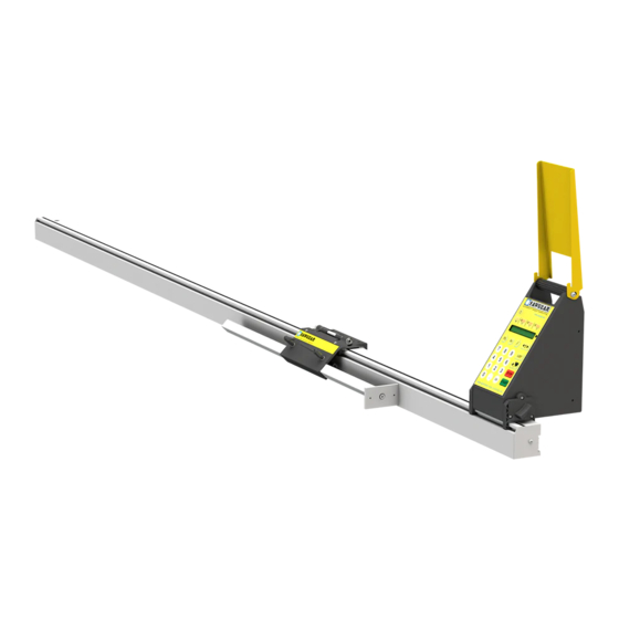
Page 8: Parts Inventory
Parts Inventory POWER HEAD DESCRIPTION PART QUANTITY (NUMBER) SawGear Power Head (SA2520) Power Cable (PC) FLIP-AWAY STOP ASSEMBLY DESCRIPTION PART QUANTITY (NUMBER) Flip-Away Stop (SA2545) M6 Adjustable Handle (F7306) - Page 9 Parts Inventory STOPS DESCRIPTION PART QUANTITY (NUMBER) Stop Bar (SA2555) Crown Moulding Foot (Optional) (SG-CMF) BENCH MOUNT ASSEMBLY DESCRIPTION PART QUANTITY (NUMBER) Bench Mount Bracket (M1016) M8 Star Knob (F7304) Bench Mount Hardware Pack (F0038)
- Page 10 Parts Inventory POWER HEAD CONTROLLER (OPTIONAL) DESCRIPTION PART QUANTITY (NUMBER) SawGear Power Head (PH-PS) & SawGear Power Head Controller (PS-CON) Power Cable (PC) POWER HEAD CONTROLLER STAND (OPTIONAL) DESCRIPTION PART QUANTITY (NUMBER) SawGear Controller Mount (M1047) M5x8mm Socket Head Screw...
- Page 11 Parts Inventory DESCRIPTION PART QUANTITY (NUMBER) Round Tube (M1807) Controller Stand Base Bracket (M10070) M6x14mm Socket-Head Screw (F7216) M6x10mm Socket-Head Screw (F7208) M8x50mm Hex-Head Screw (F9827) M8x45mm Hex-Head Screw (F9826) Spacer (F6702) M8x35mm T-Bolt (F0184) Flange Nut (F0419)
- Page 12 Parts Inventory PANEL SAW RETROFIT KIT (OPTIONAL) DESCRIPTION PART QUANTITY (NUMBER) Cable Guard (M9959) Universal Bracket (M5100) Universal Bracket Hardware Pack (F0032) Control Stand Base Half-Bracket (M10070) Round Tube (M1807) M6x25mm Leveling Foot (F9848) Foot Adapter (M10180)
- Page 13 Parts Inventory DESCRIPTION PART QUANTITY (NUMBER) M6x8mm Set Screw (F4005) M8x50mm Hex Head Screw (F9827) M8 Flange Nut (F0419) M5x16mm Flat Head Screw (F1016) M5 Washer (F9847) M5 Hex Nut (F2001)
-
Page 14: Sawgear Installation
VOLTS CIRCUIT BREAKER 208/230/240V SawGear requires a dedicated, grounded circuit. Operating SawGear without proper grounding risks electrocution. SAWGEAR BENCH MOUNT BRACKETS Secure SawGear in the brackets Make sure both Bench Mount Brackets are approximately in line. Fasten them in place with the supplied hardware. - Page 15 Turn the locking knobs to secure SawGear. Always firmly tighten the locking knobs and all fasteners before using SawGear. Dismounting SawGear from the saw stand Dismount SawGear from the saw stand by loosening the locking knobs and pivoting it off the brackets.
-
Page 16: C Onnecting The F Lip -A Way S
Remove the rod from the Flip-Away Stop. Insert the Adjustable Handles and tighten with their supplied hardware. Align the cylinders of the Flip-Away Stop and SawGear carriage and insert the rod’s washers between them. Re-attach the rod to connect them. - Page 17 SawGear Installation CONNECTING THE POWER HEAD Insert the Power Head into either of the SawGear beam’s attachment points. Ensure it is rotated slightly counter-clockwise when inserted. Rotate into place, clockwise. Turn the knobs on both sides to secure the Power Head to the beam.
-
Page 18: Sawgear Operation
SawGear Operation SAWGEAR CONTROL PANEL [Sleep] Puts the Power Head to sleep to save energy. [W] Moulding Width Entry for miter cuts. [X] Left Inside Length Entry for miter cuts. [Y] Header Inside Length Entry for miter cuts. [Z] Right Inside Length Entry for miter cuts. - Page 19 Select a language when prompted. SawGear can display text in English, Spanish, French, Dutch, and German. Press to select a measurement system. Press if the saw is to the left of SawGear, or if the saw is to the right.
- Page 20 If the displayed working length is incorrect, enter the correct working length (in mm) found on the back side of the SawGear’s beam. SawGear backs out and stops at 6” (152mm). CUT a sample at this length and MEASURE it. Enter the length of the sample and press...
-
Page 21: Et C Ontrast
•When powered OFF or asleep, SawGear’s display is off. •To wake SawGear up, push and the display turns on. •If Password Protection is enabled, SawGear requires password entry whenever SawGear is powered-on or awoken. SLEEP MODE SawGear will automatically sleep after ten minutes of inactivity. - Page 22 SawGear Operation PASSWORD PROTECTION Secure SawGear with a password to prevent its use by unauthorized persons. After setting a password, SawGear cannot be operated without it. DON’T LOSE IT! Unplug SawGear from AC power. While holding down , plug SawGear into AC power.
-
Page 23: 18 D Eactivate The P Assword
Press twice again. This clears the password. Press SawGear is now ready to use! SawGear no longer requires a password when powered-on/awoken. INCREMENT Make small incremental moves by pressing the increment button: The increment button is two buttons in one. - Page 24 Enter any number from 0 to 9. If the displayed list number is incorrect, exit by pressing [Stop]. Press SawGear will move to each new dimension as it is entered. Ensure nothing is in the way. Enter and press The dimension displays exactly as entered.
- Page 25 SawGear moves to position at 6_5/8 inches. RULE: An underscore separates inches from fractions when at position. Enter press SawGear moves to position at 3 feet 6_5/8 inches. RULE: “ft” follows feet and a space separates feet from inches when at position. Enter and press awGear moves to position at 3 feet 6 inches.
-
Page 26: Ntering M Illimeters
SawGear moves to position at 3 feet 9.875 inches. RULE: SawGear interprets any number entered after as inches. ENTERING NON-STANDARD FRACTIONS Enter a non-standard fraction of an inch and SawGear moves to the exact position. Enter and press SawGear moves to position at 16-2/3 inches, but the display shows the position as 16_21/32. -
Page 27: Ntering N Egative N Umbers
SawGear Operation ENTERING NEGATIVE NUMBERS SawGear is in Inches mode for this example. Enter Enter and press SawGear moves to position at minus 3/4”. CALIBRATION Set the distance between the stop and the saw blade using the Calibrate button: The Calibrate button sets five distances:... - Page 28 Calibrate Miter Cut: X Distance The calibration of the X, Y and Z values uses a calculated value base on the value of W (moulding width). SawGear will use the value of W to calibrate X, Y, and Z values. Press...
- Page 29 SawGear moves to a length based on the width of the stock and the 45° angle of the last miter. 10. Move the part to the stop, return the saw to 0°, make the final square cut, and remove the right part.
- Page 30 SawGear moves to a length based on the width of the stock and the custom angle of the last miter. 11. Move your part to the stop, return the saw to 0°, make the final square cut, and remove the right part.
-
Page 31: Pivot Point Calibration
Check the Pivot Point This example assumes that SawGear is on the right of the saw, and that the observed pivot point is on the right side of the saw blade. Check for accuracy by comparing the straight cut and the left & right miter cuts: End trim a sample board. - Page 32 Pivot point too far BACK Pivot point too far FORWARD Using SawGear to Adjust Pivot Point If the back fence of the saw is fixed, adjust the pivot point offset using SawGear’s pivot point adjustment system. Press then press If SawGear calibration is necessary, press calibrate as usual.
-
Page 33: Crown + Miter Pro
Crown + Miter Pro The Crown & Miter Pro feature calculates saw angles for crown and base moulding while ensuring accurate cut lengths. GETTING STARTED To activate the Crown & Miter Pro feature: Press twice. Press then Measuring Angles and Lengths Start with the longest wall and, working counter-clockwise around the room, make a list of angles and cut lengths. - Page 34 Press to select if this is an inside or outside corner. The required saw angle displays. Set the saw, press , and SawGear moves to the proper length for the cut. [Y] Button sets the part length. Press and the following screen displays: ‘B’...
- Page 35 From table 1 above we can see it’s 45° and an outside corner. After angle entry, SawGear displays the required saw angle and direction. Set the saw and cut your first angle. Press Enter the length of the part.
-
Page 36: Troubleshooting
The following example shows how to correct an entry error using the Clear button: Enter You entered 3/8 by mistake. It should have been 5/8. Press SawGear erases digits starting with the last digit entered. Enter Your new entry replaces the error. Press SawGear moves to position at 32-5/8 inches. - Page 37 Troubleshooting HOME ROUTINE AFTER IMPACT If material is thrust against SawGear with sufficient force, it can bump the stop off position. Whether it does or not, a warning message appears to allow for re-homing the machine or continuing work. As a sensible precaution, choose to re-home it.
-
Page 38: Appendix A: Power Head Controller Stand
Appendix A: Power Head Controller Stand ASSEMBLY 1. Place the Controller Stand Base Brackets against the Round Tube and insert two M8x45mm Hex-Head Screws through all three parts. 2. Fasten the Base Brackets to the round tube with M8 Flange Nuts. 3. -
Page 39: Appendix B: Panel Saw Retrofit
Appendix B: Panel Saw Retrofit UNIVERSAL BRACKET INSTALLATION Use the supplied Universal Bracket Hardware Pack to fasten the Universal Brackets to the base of the panel saw. Ensure the brackets are level and in alignment with each other. Installing the brackets may require drilling and tapping. BENCH MOUNT BRACKET INSTALLATION Install one Bench Mount Bracket to each Universal Bracket. - Page 40 Appendix B: Panel Saw Retrofit SAWGEAR MOUNTING Secure the SawGear in the Bench Mount Brackets according to the instructions page 8. ASSEMBLE SUPPORT LEG Leveling Nuts Fasten the Foot Adapter to the Round Tube with an Place the Controller Stand Base Brackets against the M6x8mm Set Screw.
- Page 41 M5 Washers, and M5 Hex Nuts to fasten the Tube. brackets. ATTACH SUPPORT LEG Attach the Support Leg to the far end of the SawGear from the blade. Ensure the Star Knob is facing the user and adjust the Leveling Foot until the SawGear is level throughout.
- Page 42 Appendix B: Panel Saw Retrofit CONNECTING THE POWER HEAD Locking Handle Connect the Power Head as described on page 11. Make sure the cable is facing the user, in this case. CONNECT CABLE GUARD TO POWER HEAD Remove the 4 screws on the sides of the Power Head. Hold the Cable Guard in alignment with the fastener-holes and replace the 4 Power Head screws.
- Page 43 Appendix B: Panel Saw Retrofit CONNECTING THE FLIP-AWAY STOP Follow the instructions on page 10 connect the Flip-Away Stop. ATTACHING THE STOP BAR Lock Follow the instructions on page 10 attach the Stop Bar.
- Page 44 Appendix B: Panel Saw Retrofit ATTACH CONTROLLER TO SAW Use fasteners appropriate to the saw to attach the Power Head Controller. Attaching the Controller may require drilling and tapping.
- Page 45 TigerStop Product COMPARISON CHART Power Working Max Load Product Drive Type Accuracy Requirement Length Push 2 AA +/- .008” 0’ - 20’ Caliper TigerSPC +/- 0.2mm 0m - 6m Battery 32mm Belt +/- .008” 8’ - 20’ SawGear Stop Only 110 Vac +/- 0.2mm...
Need help?
Do you have a question about the SawGear and is the answer not in the manual?
Questions and answers