
Related Manuals for Raycus RFL-C15000M-HP


Summary of Contents for Raycus RFL-C15000M-HP
- Page 1 RFL-C15000M-HP RFL-C20000M-HP CW Fiber Laser Product Manual Wuhan Raycus Fiber Laser Technologies Co.,Ltd en.raycuslaser.com...
- Page 2 Continuous-Wave Fiber Laser User Guide for RFL-C15000M-HP~C200000M-HP Model: RFL-C15000M-HP RFL-C20000M-HP WuhanRaycusFiberLaserTechnologiesCo., Ltd.
- Page 3 CONTENTS 1 Safety Information ............................1 1.1 Security Label ..........................1 1.2 Laser Safety Grade .......................... 2 1.3 Optical Safety ..........................3 1.4 Electrical Safety ..........................3 1.5 Other Safety Rules .......................... 3 2 Product Description ............................4 2.1 Features ............................4 2.2 Package Parts ...........................4 2.3 Unpacking and Inspection .......................4 2.4 Operation Environment ........................
- Page 4 7 RS232 and ETHERNET Communication Command ................39 7.1 Port Configuration .........................39 7.2 Laser Communication Protocol (Network Port & Serial Port) ............. 39 8 Raycus PC Software Instructions ......................44 8.1 Main Interface of PC Software ......................44 8.2 Multi-laser Control Area ....................... 44 8.2.1 Add/Delete Laser ........................45...
- Page 5 8.3.2 Laser Working Status Display Area ...................47 8.3.3 Laser Power-up, Mode Selection, Light-out Control Area ..........48 8.3.4 Programming Mode Area ....................49 8.3.5 Power Slow Rise & Down Parameter Setting Area ............49 8.3.6 Laser Output Parameters Read the Settings Area .............. 50 8.4 Laser Parameter Display Area .......................50 8.5 Alarm Type Display Area ......................
- Page 6 1 Safety Information Thank you for choosing Raycus Fiber Laser. This user manual provides you with important safety, operation, maintenance and other relevant information. Please read the manual carefully before using this product. To ensure safe operation and optimum product operation, please observe the following cautions and warnings as well as other information within this manual.
- Page 7 CAUTION: Describes a hazard that leads to general injury to people or damages to product. English English (20000W) English Chinese Chinese (20000W) Chinese 3: Class 2 Laser Product Label-1mW 1:Laser Emit Head 2: Type 4 Laser Product Red Laser 4: CE Authentication 5: ID Label (20000W) 6: Laser Radiation Hazard 7:Electrical Hazard...
- Page 8 WARNING:Users must use appropriate laser goggles when operating this device. The laser goggles should be selected according to the range of wavelength emitted from this product. Users must ensure that the protect range of laser goggles over the entire range of laser wavelengths.
- Page 9 Once you find that there is an abnormality in the external cabinet, please inform Raycus Company in time to deal with it as soon as possible. Please double check if each listed content is inside the package; and contact Raycus as soon as possible if there are any issues.
- Page 10 Take extra care when removing the unit from the package and make sure that the fiber optic cable stays away from any possible collision and vibration. Please DO NOT distort, bend or pull the output cable when unpacking the device; and avoid any collision to the head of laser output. CAUTION: The fiber optic cable and output head are precise optic instrument, Any vibration or impact to the output head, and twist or excessive bend to the cable will damage the instrument.
- Page 11 Safety keep the cap when using the laser. To avoid dust, make sure the opening direction of the cap is put down. Failure to follow the instructions may cause laser power loss, such loss is not covered by warranty. 2.6 Features The optical, electrical and other properties of RFL-C4000M-HP/ RFL-C20000M-HP lasers are listed in Table 2.
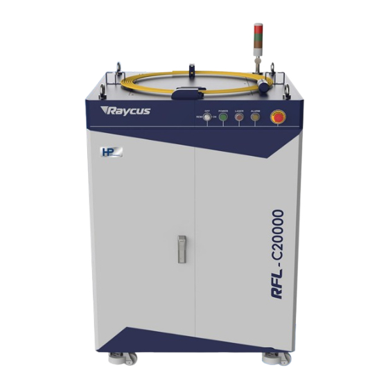
- Page 12 Weight (kg) (Includes air <600 <700 conditioning) Operating Ambient 10~40 Temperature (°C) Humidity (%) 30~70 Storage -10~60 Temperature (°C) Cooling Method Water cooling 3 Installation 3.1 Dimensions The main body dimensions of RFL-C20000M-HP continuous fiber laser are shown in Figure 2. (a) Front view (b) Rear view...
- Page 13 The structure size of RFL-C15000M-HP/RFL-C20000M-HP laser is 960x1530x1160mm (width×height×depth; including casters and rings, without warning light); RFL-C15000M-HP laser weighs less than 600kg.RFL-C20000M-HP laser weighs less than 700kg. The 15kW continuous fiber laser uses the RFL-QD output optical cable, and the external dimensions of the output optical cable head are shown in Figure 3(a).
- Page 14 If the output cable lens is dirty, the lens must be cleaned. It is forbidden to disassemble the output lens by anyone other than staff in Raycus, otherwise the warranty will be invalidated.
- Page 15 CAUTION: (1) The placement of the laser output cable should be as natural as possible, and the output cable should not be twisted; (2) If the coil diameter of the output optical cable is too small, it will damage the laser. CAUTION: (1) In the process of installation and disassembly, please handle the laser output head gently, and avoid vibration;...
- Page 16 Figure 4 Schematic diagram of the protective end cap of the optical cable 3.3.2 Pre-installation Cleaning Instructions for Output Cables A) Preparation tools Cleaning agent: absolute ethanol, or isopropyl alcohol. Cleaning tools: cleaning cotton swabs, dust-free paper, compressed air bottles, etc. B) Steps a) Clean workbench should be turned on for at least 5 minutes, and the output optical cable should be taken out of the black packaging box, as Figure 5.
- Page 17 Note: The following operations need to be carried out in a clean workbench. If the operation is not carried out in a clean environment, it will cause great risk to the output optical cable; operators need to wear finger cots to operate. Figure 6 The output optical cable placed in the clean bench with the ventilation turned on c) Remove the white dust cap and place it face down on new lint-free paper.
- Page 18 Figure 8 Remove the A -type end cap on the optical cable e) Check the cleanliness of the end caps in this state. If the cleanliness is not enough, please clean the end caps. Please refer to the cleaning method: http://www.raycuslaser.com/view/1852.html Reference video:https://mp.
- Page 19 type A , and the white dust cover must be covered, and finally put into a black box for transport. Figure 9 Accessories that customers need to keep: black protective box, white dust cover, type A end cover 3.4 Cooling Requirements Table 4 Cooling requirements C15000 C20000...
- Page 20 If ambient temperature is below -10℃, the chiller with both heating and cooling functions must be used, and keep it in full-time operation; f) For the connection of cooling water and normal temperature water circuits,please use Raycus supporting water pipes. If the water pipes are self-distributed,please do not increase the length of the water pipes and change the inner diameter of the water pipes;...
- Page 21 (2) Before turning on the laser, the cooling system must be working properly and the water temperature should be suitable for the temperature. 4 Using the Product Please log in to the official website of Raycus to download the new PC software and the PC software user manual. Website: http://www.raycuslaser.com...
- Page 22 4.1 Front Panel Figure 11 shows the front panel. ⑥ ① ② ③ ④ ⑤ Figure 11 Front view of the panel Note: -REM/OFF/ON -POWER -START -ALARM -STOP -INDICATOR LIGHT ① ② ③ ④ ⑤ ⑥ REM/OFF/ON: The key switch, the main control switch of the laser. Insert the key and turn it to the "ON"...
- Page 23 INDICATOR LIGHT: After the main power supply of the laser is powered on, the green indicator light is on when the laser is Ready; when the laser is emitting light, the red indicator light is on; when the laser has a fault, the yellow indicator light is on, accompanied by an alarm sound. 4.2 Rear Panel Figure 12 shows the rear panel (take C20000M-HP as an example).
- Page 24 ③-AC INPUT: The power input socket must be matched with the plug provided by us. This socket comes with a protective cover and a lock. When you are not using the product, you can cover the power input socket with the protective cover and lock it with the lock. ④-WATER IN: The water inlet of the laser, this interface is connected to the water outlet of the cooling water of the water chiller, and connected to the φ38 inner diameter water pipe.
- Page 25 Protective 16mm Yellow-green C15000M-HP and C20000M-HP provided by Raycus is 15 meters. 4.4 Control Interface Definition This type of laser does not provide a control signal line, except a control signal connector. The appearance of the joint is shown in Figure 15.
- Page 26 HARDWIRING Security Interface Analog Interface Serial Interface RS232 Communication Interface Figure 15 Control signal line 4.4.1 Safety XP2 Interface 24-pin safety interface, with remote control system power-on, remote main power power-on and active and passive output of some lasers. The detailed interface definition is shown in Table 6. Table 6 XP2 security interface definition Pin No.
- Page 27 On REM mode, the main control board is powered on when pin-8 and pin-9 are closed; 24V active contact output, no external voltage or grounding. Connect the positive pole of the external power-on indicator; 24V OUT active signal, current<400mA Emergency output 1 on the front panel, relay output contact, passive contact, current <100mA, voltage<30V;...
- Page 28 When A8~A14 are all low, A2 is the laser enable signal; if there is a high level in A8~A14, it enters the programming mode, the program command is executed from the rising edge of A2, and the program number is determined by Programming A8~A14.
- Page 29 C3 is the lowest bit, C6 is the highest bit: 0000-close all optical gate channels; 0001-open channel 1; Select the optical C3~C6 Input signal 0010-open channel 2; gate channel 0011-open channel 3. (For lasers with optical gate channels only, these pins are spare in other lasers) Enable QCW Enable QCW mode...
- Page 30 The 9-pin serial interface RS232 is used for the communication between the laser and the upper computer. It can be used to communicate with the PC software of Raycus or the software of the upper computer which integrates the communication protocol of Raycus. The definition is as follows.
- Page 31 Not connect 4.5 Introduction to Safety Interlock Raycus’ product is designed with a safe interlocking loop, which is a two-channel system with output monitoring and manual reset. When the safety interlocking circuit is open, the safety circuit will disconnect the working power of the optical module, that is, the main power supply of the optical module.
- Page 32 4.6 Schematic Diagram of the Internal Electrical Circuit of the Laser The internal electrical circuit of the laser is shown in figure 16. Figure 16 Schematic diagram of the internal electrical circuit of the laser 4.7 Start Operation Sequence a) Turn on the water cooler, check whether the water pipe is leaking, turn off the water cooler and connect electrically.
- Page 33 5 Control Mode Selection The Raycus high-power CW laser has two control modes: namely ON mode and REM mode. Users can select the mode to be entered through the key on the front panel. Table 11 Function of ON and REM mode...
- Page 34 XP1-A1 is high level, XP1-A8~A14 is not all low level; ⑪Emit laser: Send "EMON" by communication, or click button on the Raycus software Turn off the laser: Send "EMOFF" by communication, orclick button on the Raycus software; ⑫ Emit light: Send "ABN"...
- Page 35 When the red light is on, the laser cannot be set to “Ready”. Only after the red light is turned off the laser can be set to “Ready”. (This limit can be changed, please contact Raycus Engineer). 5.5 Programming Mode In “ON”...
- Page 36 When the red light is on, the laser cannot be set to Ready. Only after the red light is turned off the laser can be set to “Ready”. (This limit can be changed, please contact Raycus Engineer). 5.6.4 Programming Mode When A1 of XP1 is set high and A8-A14 is not 0, the laser is in “Programming Mode”.
- Page 37 Turn the knob switch on the rear panel to“ON” Turn the key switch to“ON” Open the Raycus PC software Click the guide laser “ON” button to view the guide laser Turn off “AD” mode and turn off external control mode (this mode can be memorized when power off) f) Click the main power “ON”...
- Page 38 Turn the knob switch on the rear panel to“ON” b) Turn the key switch to“ON” c) Open the Raycus PC software d) Click the guide laser “ON” button to view the guide laser e) Turn off “AD” mode and turn on “External Control” mode (this mode can be memorized after power off) f) Click the main power “ON”...
- Page 39 Turn the knob switch on the rear panel to“ON” Turn the key switch to“ON” Open the Raycus PC software Click the guide laser “ON” button to view the guide laser Turn on the “AD” mode and turn on “External Control” mode (this mode can be memorized after power off) f) Click the main power “ON”...
- Page 40 Start waveform at the rising edge of MOD signal. NOTE: The high-level time of MOD must be greater than the program running time. If MOD gives a falling edge in advance, the Raycus PC software will display that the laser program is abnormally terminated.
- Page 41 0V and turn off the guide laser f) XP1-C1 is connected to 24V, and the main power is turned on (operator can also directly press the LASER button, or clicks the main power “ON” on the Raycus PC software) Waiting for “Ready”...
- Page 42 0V and turn off the guide laser f) XP1-C1 is connected to 24V, and the main power is turned on (users can also directly press the “LASER” button, or clicks the main power “ON” on the Raycus PC software) Waiting for “Ready”...
- Page 43 The Raycus PC software sets the power, XP1-A2 is connected to 24V, and the control board card outputs MOD signal 6.7 Programming Mode in REM Mode Figure 24 Wiring diagram of programming mode in REM Mode Operations Steps: Turn the knob switch on the rear panel to“ON”...
- Page 44 Figure 25 Timing diagram 7 RS232 and ETHERNET Communication Command 7.1 Port Configuration RS-232 configuration is as follows: Baud rate :9600, data bit :8, stop bit :1, no parity bit and no control flow. Ethernet port is configured as follows: Default laser IP address :192.168.0.10 Laser port :10001 7.2 Laser Communication Protocol (Network Port &...
- Page 45 Table 12 Specific protocol contents and command examples of laser Command Description Command example Send: ‘ABF\r’ Aiming Beam OFF –Turn off red Return: ‘ABF\r’ Send: ‘ABN\r’ Aiming Beam ON – Turn on red Return: ‘ABN\r’ Send: ‘DEABC\r’ DEABC Disable External Aiming Beam Control Return: ‘DEABC\r’...
- Page 46 Set Diode Current (%) Send: ‘SDC 100\r’ The set value must be less than 100% and above Return: ‘SDC:100\r’ the minimum current setting value, which can be Other return values: set to 0. If the set value is greater than 100, the ‘ERR: Input Err\r’...
- Page 47 Disable Calibration Mode Send: ‘DCM\r’ (AD analog response time is less than 100 us in Return: ‘DCM\r’ this mode) Send: ‘BGM\r’ Others Command Error Return: ‘Command Err!\r’ Read Device Status – Read the product status. A return value of 32-Bit digital information.
- Page 48 Normal Bit 13 Leakage sensors 1 leaking Normal Bit 14 Leakage sensors 2 leaking No laser Bit 15 Laser is power on Gate mode=off Bit 16 Gate mode=on AC input normal Bit 17 AC input abnormal External Emission control=off Bit 18 External Emission control=on Normal Bit 19...
- Page 49 Optical circuit safety interlock abnormal Normal Bit 31 High average power 8 Raycus PC Software Instructions Raycus PC software download address: http://www.raycuslaser.com/list/56.html 8.1 Main Interface of PC Software The PC software’s main interface shows as Figure 26. Figure 26 PC software’s main interface 8.2 Multi-laser Control Area...
- Page 50 Figure 27 Multi-laser control area interface Select IP address of corresponding laser, then double click. PC software will take communication with selected laser.After the communication established, the lower left status display shows that the network connection is fine, as Figure 28. Figure 28 Communication status interface between PC software and laser 8.2.1 Add/Delete Laser You can add/delete laser in the laser list area by right-click to add/delete In the PC software.
- Page 51 Figure 29 Procedure for adding a laser to the PC software 8.2.2 Modify Laser IP After the laser connection has established, select the IP address of current laser and right-click to set it up as Figure 30. Figure 30 Modify the IP address of laser...
- Page 52 8.3 Main Working Status Display The laser’s main status display is as Figure 31, and the meaning is as Table 13. Figure 31 A diagram of the laser's main display area Table 13 The laser main display content and meaning Display Meaning Output power...
- Page 53 Figure 33 A diagram of the laser's working status display area Table 14 The laser main display area meaning Display Meaning Red: emergency button on front panel is pressed; Emergency Gray: emergency button is reset. Green: laser works in REM mode; Gray: laser works in ON mode.
- Page 54 Figure 34 Laser power-on, mode selection, light out control display area Table 15 Laser power-on, mode selection, light out control display area meaning Display Meaning Main power button Click ON, main power on; click OFF, main power off External control Click ON, activate laser external control;...
- Page 55 Figure 36 The power slow rise and fall setting area interface and measured programmings 8.3.6 Laser Output Parameters Read the Settings Area Laser output parameter setting interface is as Figure 37 The output parameter setting is not valid when AD mode is on. Figure 37 Laser output parameter setting area display interface 8.4 Laser Parameter Display Area The display interface for laser parameter display area is as Figure 38The module status is used to...
- Page 56 Figure 38 Laser parameter display area display interface 8.5 Alarm Type Display Area The laser alarm type display area interface is as Figure 39This interface shows the cause of the alarm for the current laser. Figure 39 Laser alarm type display area interface 8.6 PC Software Operating Mode Selection The laser operating mode is set by the PC software.
- Page 57 Figure 40 Laser operating mode selects the display area interface Table 16 Laser operating mode and explanation Mode selection Mode explanation Monitor A concise software interface, which can monitor basic status information Supports the selection of control modes, such as AD mode, external control Control mode, and programming mode Diagnostics...
- Page 58 Figure 41 Language selection interface 8.8 Authorization (Time-Limited Locking) 8.8.1 Authorization in User Mode The authorization settings in user mode are as Figure 42 Laser can be locked and unlocked by valid authorization code.
- Page 59 Figure 42 The authorization settings operating interface in user mode 8.8.2 Authorization in Authorization Mode The authorization settings in laser authorization mode are as Figure 43 This interface allows the customer to lock and unlock the machine and can also be used as an authorization code generator. The locking time setting can set the effective using time of laser.
- Page 60 Figure 43 Authorization settings operating interface in authorization mode 8.9 About Laser relevant information such as date of manufacture, model, serial number, controlling serial number, token version number, system information and other information can be queried in the PC software ‘about’ item. Specific interface is as Figure 44 Figure 44 Laser relevant information query interface...
- Page 61 8.10 XP1 Interface Status Indication (in Diagnostic Mode) The laser interface status indicator interface is as Figure 45 It is convenient to view the interface status information which represents the input and output status of the XP1 interface on the back panel. Figure 45 The interface status in diagnostic mode 8.11 Log (in Diagnostic Mode) Laser’s working log interface is as Figure 46 User can query work log by entering the time to query...
- Page 62 Figure 47 Log download interface 8.11.2 Download Record of Historical Fault Historical fault record download interface is as Figure 48 Figure 48 Historical fault record download interface 8.11.3 Downloaded File Address The file address query interface for all download information is as Figure 49...
- Page 63 8.12 Module Parameters (in Diagnostic Mode) Laser module parameter query interface is as Figure 50 The interface is for the parameter query in diagnostic mode from which Raycus technicians can analyze the cause of laser anomalies. Figure 50 Module parameters query interface in diagnostic mode 8.13 Programming Settings (Programming Editing)
- Page 64 Figure 51 The programming interface in programming editing mode 8.13.1 View the Number of Wave Bars inside the Current Laser Operating interfaces of view the number of wave bar stored inside the current laser is as Figure 52 The software automatically lists the number of wavelength bars that have been saved by click on the ‘Refresher List’...
- Page 65 8.13.2 Check Waveform Content To check the programming contents in the current laser programming mode is as Figure 53 The program automatically lists the original programmings by click the programming number that needs to be checked. Figure 53 Programming content interface in the current laser programming mode 8.13.3 Empty all Waveforms Empty all programming interfaces stored in the current laser programming mode is as Figure 54 All programmings stored inside the current laser.
- Page 66 Figure 54 Interface of empty all programming stored in the current laser programming mode 8.13.4 Edit Waveform Programming editing when the laser is working in programming mode is as Figure 55 Step 1:left click the pre-edited programming number. Step 2:select the command under the command type, click ‘Add’. Step 3:enter the parameters and click ‘Save’.
- Page 67 (a) Select the pre-edited programming number Figure 55 A diagram of the programming editing operation in programming mode...
- Page 68 8.13.5 Command Explanation Command meaning in laser working status is as Table 17. Table 17 command meaning in laser working status Code (1 Byte) Parameter1 (2 bytes) Parameter 2 (4 bytes) Note The program end command. the last Stop None None command must be this command.
- Page 69 Raycus has the right to selectively repair or replace any product that has a material or technical problem during the warranty period. All products repaired or replaced during the warranty period only provide free warranty services for products with special problems.
- Page 70 Raycus reserve the right to make changes in design or constructions of any of our products at any time without incurring any obligation to make changes or install the same on units previously purchased.
Need help?
Do you have a question about the RFL-C15000M-HP and is the answer not in the manual?
Questions and answers