Table of Contents
Advertisement
Quick Links
Advertisement
Table of Contents

Related Manuals for EXFO BV10


Summary of Contents for EXFO BV10
- Page 1 Installation Guide BV10 Performance Endpoint Unit...
- Page 2 EXFO Inc. (EXFO). Information provided by EXFO is believed to be accurate and reliable. However, no responsibility is assumed by EXFO for its use nor for any infringements of patents or other rights of third parties that may result from its use.
- Page 3 European Community Declaration of Conformity An electronic version of the declaration of conformity for your product is available on our website at www.exfo.com. Refer to the product’s page on the Web site for details. Laser This product complies with 21 CFR 1040.10 except for deviations pursuant...
-
Page 4: Table Of Contents
Installation Instructions Installation Instructions This document describes the basic steps for installing the BV10. Refer to the BV10 user guide for more information. Contents Page Getting Started Installing the BV10 in a Rack Connecting the Power Physical Interfaces, LEDs, and Buttons... -
Page 5: Getting Started
Getting Started Installing the BV10 in a Rack The BV10 can be mounted in a rack using the rack mount accessory kit (ordered separately). The accessory kit shelf holds up to four BV10. To install the BV10 in a rack: 1. -
Page 6: Connecting The Power
The BV10 is available with either an AC power supply, DC +24 V connector, or DC –48 V connector. As soon as the BV10 is connected to a live power supply, the POWER LED turns on. If the POWER LED does not turn on, there is a power failure at the source or the unit is damaged. - Page 7 You will need to supply a #12 AWG wire. ARNING The BV10 DC version is intended to be grounded. Ensure that the unit is connected to earth ground during normal use. AC unit ground...
- Page 8 2. Connect the other end of the power supply to the DC barrel power connector on the BV10. Connecting the BV10 using a DC Power Source The BV10 DC version is equipped with either +24 V DC or –48 V DC connector. ARNING Powering a BV10 +24 V DC unit with a –48 V power source will...
- Page 9 Negative ( ) supply wire lead on the left Positive (+) supply wire lead on the right 2. Connect the plug to one of the two DC input connectors on the BV10 unit and tighten the screws firmly. BV10-100 and BV10-1000...
- Page 10 The switch must be specified as the disconnecting device for the equipment. 4. To add a redundant DC power source on the BV10, repeat step 1 through step 3. ARNING To avoid serious injuries as well as irreparable damages to your unit, ALWAYS TURN OFF BOTH DISCONNECT DEVICES BEFORE OPENING OR SERVICING THE UNIT.
-
Page 11: Physical Interfaces, Leds, And Buttons
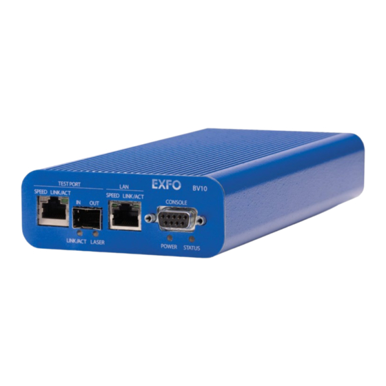
Physical Interfaces, LEDs, and Buttons This section describes all connectors (ports), LEDs, and buttons available on the BV10-100 and BV10-1000 units. BV10 Models BV10-100 CONSOLE TEST BV10-1000 CONSOLE TEST Laser radiation emitted from this port when LASER LED is on. -
Page 12: Port Availability On Bv10
Connecting the TEST Port Interface The BV10-100 provides an electrical 10/100 Mbit/s Ethernet Test interface while the BV10-1000 provides an electrical 10/100/1000 Mbit/s and an optical 1000 Mbit/s SFP laser Ethernet Test interfaces. The two BV10-1000 Test interfaces are mutually exclusive. RJ45 Port Connect the 10/100/1000 Mbit/s electrical interface to be tested to the RJ45 test port. - Page 13 The optical port is a Small Form Factor Pluggable (SFP) slot type with LC connector. Insert an SFP module into the SFP test port slot on the BV10. Refer to Optical Interface on page 95 for more information on supported SFP .
-
Page 14: Connecting The Management Interfaces
LAN port provides remote access to the BV10 Command Line Interface (CLI) using either Telnet or SSH session. To connect remotely to the BV10 using the LAN port, connect both the BV10 LAN port and the remote PC to the same Management network using a standard straight through Ethernet cable with RJ45 connectors. - Page 15 Physical Interfaces, LEDs, and Buttons Connecting the Management Interfaces CONSOLE Port Connecting a PC to the CONSOLE port provides local access to the BV10 using CLI commands. The following figure shows the DB9 (RS-232 DE-9F DCE) pinouts as viewed from the front of the BV10.
-
Page 16: Leds
Physical Interfaces, LEDs, and Buttons LEDs LEDs POWER On (Green) indicates that the BV10 unit is receiving power from an external source. Off indicates that the BV10 unit is not receiving power from the external source or the unit is damaged. -
Page 17: Reset And Default Buttons
Physical Interfaces, LEDs, and Buttons RESET and DEFAULT Buttons RESET and DEFAULT Buttons The RESET and DEFAULT buttons are recessed on the back of the BV10 to avoid accidental use. RESET DEFAULT RESET Button The RESET button is used to reboot the BV10. Press the RESET button once to reboot the BV10. - Page 18 Tel.: 1 978 367-5600 · Fax: 1 978 367-5700 EXFO FINLAND Elektroniikkatie 2 FI-90590 Oulu, FINLAND Tel.: +358 (0) 403 010 300 · Fax: +358 (0) 8 564 5203 TOLL-FREE (USA and Canada) 1 800 663-3936 © 2014 EXFO Inc. All rights reserved. Printed in Canada (2014-12) ...
Need help?
Do you have a question about the BV10 and is the answer not in the manual?
Questions and answers