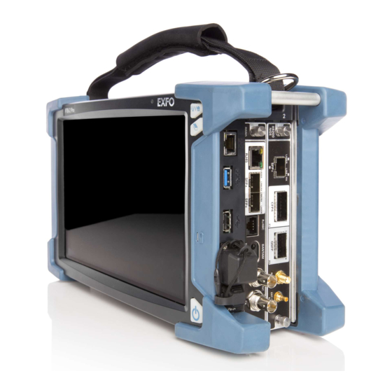
Page 1
User Guide HIGH-SPEED MULTISERVICE TEST MODULE Power Blazer 88000 Series www.EXFO.com...
Page 2
EXFO Inc. (EXFO). Information provided by EXFO is believed to be accurate and reliable. However, no responsibility is assumed by EXFO for its use nor for any infringements of patents or other rights of third parties that may result from its use.
Page 3
5 Graphical User Interface Overview ............31 Main Application Window ....................31 Main Window ........................31 Navigation Buttons .......................32 Status Bar ..........................32 Title Bar ..........................35 Global Indicator ........................36 Test Control .........................38 Test Menu ..........................38 Application Buttons ......................39 Zoomed-In/Zoomed-Out Views ....................43 Arrow Buttons ........................43 Keyboard Usage ........................44 Power Blazer...
Page 9
15 Warranty ....................753 General Information ......................753 Liability ..........................754 Exclusions ...........................755 Certification ........................755 Service and Repairs ......................756 EXFO Service Centers Worldwide ..................757 A Specifications ................... 759 B Glossary ....................761 Acronym List ........................761 10G Ethernet Client ......................778 1588 PTP ..........................781 CPRI ...........................787...
Page 10
European Declaration of Conformity The full text of the EU declaration of conformity is available at the following Internet address: www.exfo.com/en/resources/legal-documentation. Laser Your instrument is a Class 1 laser product in compliance with standards IEC 60825-1: 2007/2014 and 21 CFR 1040.10, except for...
Page 12
Technical Specifications Model Features 8870/8880 88200NGE 88260 88400NGE/88460 Packet Sync 1588 PTP SyncE Wander 8880 Fibre Channel FC BERT Wireless CPRI/OBSAI BERT eCPRI BERT Technical Specifications To obtain this product’s technical specifications, visit the EXFO Web site at www.exfo.com. 88000 Series...
Page 13
AUTION Indicates a potentially hazardous situation which, if not avoided, may result in component damage. Do not proceed unless you understand and meet the required conditions. MPORTANT Refers to information about this product you should not overlook. Power Blazer...
Page 15
ARNING Use only accessories designed for your unit and approved by EXFO. For a complete list of accessories available for your unit, refer to its technical specifications or contact EXFO.
Page 16
Safety Information MPORTANT Refer to the documentation provided by the manufacturers of any accessories used with your EXFO product. It may contain environmental and/or operating conditions limiting their use. MPORTANT When you see the following symbol on your unit , make sure that you refer to the instructions provided in your user documentation.
Page 17
This product employs Class 1 Laser transceivers. ARNING When the LASER LED is on or flashing, the module is transmitting an optical signal on the transceiver ports. Note: Refer to the platform user guide for additional test equipment safety information and ratings. Power Blazer...
Page 18
All wiring and installation must be in accordance with local building and electrical codes acceptable to the authorities in the countries where the equipment is installed and used. ARNING Use only accessories designed for your unit and approved by EXFO. 88000 Series...
Page 19
before connecting or disconnecting cables to/from the module. before inserting or removing a transceiver to/from the module. Power Blazer...
Page 21
instability of the system, or cause irreparable damage to your modules. Note: Refer to the platform user guide for more information on how to insert/remove a module into/from the platform. Power Blazer...
Page 22
Getting Started Inserting and Removing Transceiver System Inserting and Removing Transceiver System AUTION There is no need to turn off your unit before inserting or removing transceiver systems. However, inserting/removing transceiver systems without following the instructions provided in this user documentation could result in the following consequences, depending on the operation underway when the transceiver systems are inserted/removed: unexpected behavior of the test applications,...
Page 23
The identification sticker and the protruding edges are on the left side. 4b. Insert the protruding edges of the Grooves transceiver system into the grooves of the receptacle’s module port. Power Blazer...
Page 24
Getting Started Inserting and Removing Transceiver System 4c. Push the transceiver system all the way to the back of the receptacle by pressing firmly on Screw the left edge of the transceiver system until it is fully inserted. Press on 4d.
Page 25
3b. Hold the transceiver system by the handle (NOT by the connectors) and pull it out. Do not throw away the transceiver system packaging. It is recommended to insert the transceiver system into its packaging when removing it from the FTBx-88460 module. Power Blazer...
Page 26
Getting Started Inserting and Removing Transceiver System 4. Insert the transceiver system into the FTBx-88460 module: 4a. Take the transceiver system and place it so that the handle is on the right side as shown. 4b. Insert the protruding edges of the transceiver system into the grooves of the receptacle’s Right protruding edge...
Page 27
Always pull out a transceiver system by its handle. 4. Cover the empty FTBx-88460’s receptacle with the supplied FILLER. AUTION Failure to reinstall the FILLER over an empty receptacle will result in ventilation problems. Power Blazer...
Page 28
Starting the Module Application The module can be configured and controlled by starting the application(s) as described in the following table: Module Application Comment Power Blazer 88200NGE 88400NGE 88460 88260 Power Blazer Only one application can run at once per module.
Page 29
Note: The FTBx-88260 module with TA-SFP28 transceiver systems are shown below as examples for connector location purposes. FTBx-88260 Port A Port B TA-SFP28 Port A1 Port A2 Port B1 Port B2 1. Laser radiation emitted from this port when LASER LED is on. Power Blazer...
Page 30
Physical Interfaces and LEDs TA-SFP28 Port 1 : SFP28 Port 2 : SFP28 1. Laser radiation emitted from this port when LASER LED is on. TA-QSFP28 Port 1 : QSFP28 Port 2 : QSFP28 1. Laser radiation emitted from this port when LASER LED is on. TA-CFP4 ...
Page 31
Physical Interfaces and LEDs FTBx-88400NGE EXT CLK REF OUT CFP8 SFP56 SFP28 QSFP28 1. Laser radiation emitted from this port when LASER LED is on. Power Blazer...
Page 32
Physical Interfaces and LEDs FTBx-88460 and Transceiver Systems TA4 module‘s receptacle EXT CLK REF OUT QSFP28 1. Laser radiation emitted from this port when LASER LED is on. 88000 Series...
Page 33
1. Laser radiation emitted from this port when LASER LED is on. TA4-OSFP OSFP 1. Laser radiation emitted from this port when LASER LED is on. TA4-QSFP-DD QSFP56-DD 1. Laser radiation emitted from this port when LASER LED is on. Power Blazer...
Page 34
Physical Interfaces and LEDs FTBx-8870/8880 LINK/ACT LASER EXT CLK DUPLEX LINK/RX RJ45 SFP+ SFP+ RJ48C BANTAM TX/RX2 1. Laser radiation emitted from this port when LASER LED is on. 88000 Series...
Page 35
EXT CLK Electrical port SMB for DS1/1.5M, E1/2M, 2MHz, 1PPS external clock synchronization Only OTU4 (4 Lanes) and 100GE (4 Lanes) are supported. Only parallel interfaces are supported. Available for Dual Test Set - One-Way Latency measurement mode. Power Blazer...
Page 36
Physical Interfaces and LEDs Port Availability per Module 88260 and Transceiver Systems The following table shows the list of transceiver system supported on each port of the FTBx-88260 module. Port Description Supported Transceiver System Labelled Transceiver system left port TA-SFP28, TA-QSFP28, TA-CFP4, TA-Sync Transceiver system right port TA-SFP28, TA-QSFP28, TA-CFP4, TA-Sync The following table shows the list of port as well as a description and the...
Page 37
88460 module as well as a description and the signals supported. Transceiver Description Supported Signal(s) System TA4-CFP8 Optical IN/OUT port CFP8 400 Gbit/s Ethernet transceiver TA4-OSFP Optical IN/OUT port OSFP 400 Gbit/s Ethernet transceiver TA4-QSFP-DD Optical IN/OUT port 400 Gbit/s Ethernet (QSFP56-DD) QSFP56-DD/QSFP56 200 Gbit/s Ethernet (QSFP56) transceiver Power Blazer...
Page 38
Physical Interfaces and LEDs Port Availability per Module 8870/8880 The following table shows the list of available ports as well as a description and the signals supported for each module. Module Connector Labelled Description and supported signal(s) 8870 8880 Bantam BANTAM TX and RX: DS1/1.5M, E1/2M TX/RX2...
Page 39
Before inserting an optical module into the interface receptacle, inspect the receptacle to make sure nothing is inside. ARNING Use only EXFO supported transceivers. Refer to www.exfo.com for the list of supported transceivers. Using non-supported transceivers can affect the performance and accuracy of the test.
Page 40
Physical Interfaces and LEDs Connector type is BNC for coaxial 75-ohm cable connection. An adapter cable (BNC to Bantam) is required for Bantam external clock connection (not supplied). The connector type is SMB for coaxial 75-ohm cable connection. An adapter cable (SMB to Bantam) is required for Bantam connection (not supplied).
Page 41
Graphical User Interface Overview This chapter describes the Power Blazer Series graphical user interface. Main Application Window The following main application window is displayed when the Power Blazer application is started. Title Bar Global Indicator Test Control Main Window Test Menu...
Page 42
Graphical User Interface Overview Navigation Buttons Navigation Buttons Navigation buttons appear when there is not enough room on one page to display all available test applications. The left and right arrow buttons allow respectively accessing the previous or next window. The buttons in between the left and right arrow buttons allow directly selecting the window for the type of test application listed.
Page 43
(DTS), EXFO|Worx Interop, or in Loop Up mode. Connection not established between two testing units in Dual Test Set Ethernet (DTS), EXFO|Worx Interop, or in Loop Up mode. Remote unit is busy (locked) in EXFO|Worx Interop operation mode. Ethernet Power Blazer...
Page 44
Indicates a manual change in the OH bytes transmitted. Not displayed Transport when using the default OH values. Remote PC connection established with the Power Blazer. The test is in loopback mode. Not displayed when not in loopback NI-CSU Emulation mode.
Page 45
Date and Time indicate the current date and time. Title Bar The Title Bar displays the module’s slot number in brackets, the software application name and the minimize, maximize, and close buttons. Power Blazer...
Page 46
Graphical User Interface Overview Global Indicator Global Indicator The global indicator area displays the global pass/fail verdict, global alarm, and the test duration. Global indicator area Global Verdict Current Global Alarm History Test Timer Timer The global indicator area can be maximized for distant viewing. Tap anywhere within the global indicator area to display a maximized view.
Page 47
No alarm/error has occurred during the test. Current Alarms or the name of the alarm. An alarm/error occurred in the last second. History Amber History No current alarm/error but at least one alarm/error has occurred during the test. Power Blazer...
Page 48
Graphical User Interface Overview Test Control Test Timer The test timer without the timer icon indicates the time elapsed since the beginning of the test. No timer action is active. The test timer format is “day hour:minute:second”. Timer The timer icon with Armed indicates that a start time is active. The timer icon with the Test Timer indicates that a duration and/or a stop time is active.
Page 49
Software Options button displays the list of software options. Note: For information on how to install and activate software options, refer to the platform User Guide. The Power Blazer application must be restarted once a new software option is installed in order to activate it.
Page 51
Internet Protocol Version 6 (IPv6) (up to 10GE) IPv6_40-100GE Internet Protocol Version 6 (IPv6) (40/100GE) iSAM Intelligent Service Activation Methodology L2-Transparency L2CP Handling Test in EtherSAM LINK-OAM Link OAM MPLS MPLS Encapsulation (up to 10GE) MPLS_40-100GE MPLS Encapsulation (40/100GE) Power Blazer...
Page 52
RFC 2544 test application (200/400GE) RFC6349 RFC 6349 test application (up to 10GE) RFC6349_40-100GE RFC 6349 test application (40/100GE) RFC6349-EXFOWorx EXFO|Worx Interop Operation Mode Synchronous Digital Hierarchy SONET Synchronous Optical Network SONETSDH-INTR-THRU SONET/SDH Intrusive Through Mode Tandem Connection Monitoring STS/AU and VT/TU (SONET/SDH)
Page 53
To zoom-out, tap on the magnifier (-) icon or anywhere on the block title. Arrow Buttons Moves to the top of the list. Moves one page up. Moves one line up. Moves one line down. Moves one page down. Moves to the end of the list. Power Blazer...
Page 54
Graphical User Interface Overview Keyboard Usage Keyboard Usage The GUI pops up different keyboards to modify data. Following are the usual keyboard keys: Left arrow moves the cursor one position to the left. Right arrow moves the cursor one position to the right. ...
Page 55
For multiplexing keyboard, tap on all mapped signals that have to be added/removed to/from the test path. A mapped signal with an orange background color is part of the test path. A mapped signal with a gray background color is not part of the test path. Power Blazer...
Page 56
Graphical User Interface Overview Keyboard Usage The Trace message keyboard allows entering alphanumerical characters (ITU T.50) required for J0/J1/J2/TTI Trace fields. Tap the Control Characters button to access these characters. ITU T.50 Characters b7 to b1 Character Description b7 to b1 Character Description 000 0000 Null...
Page 57
Test Setup - Test Applications The Power Blazer offers the following test applications. Available on Type Application Page 8870/8880 88200NGE 88260 88400NGE/88460 Intelligent Apps iOptics iSAM Transport OTN BERT Multi-Channel OTN FlexO BERT SONET/SDH BERT OTN-SONET/SDH BERT DSn/PDH BERT SONET/SDH - DSn/PDH BERT...
Page 58
Test Setup - Test Applications Available on Type Application Page 8870/8880 88200NGE 88260 88400NGE/88460 Wireless CPRI/OBSAI BERT eCPRI BERT 88000 Series...
Page 59
Typical iOptics test application: EXFO Unit Supported Interfaces/Rates: 40G/100G/400G/OTU3/OTU3e1/OTU3e2/OTU4 parallel interfaces and all serial interfaces up to 25GE/OTU2f (refer to Rate on page 176 for more information). Power Blazer...
Page 60
The Dual Test Set test allows bi-directional testing between two compatible units providing independent results for each test direction. The results from local-to-remote and remote-to-local are available on the local testing unit. Typical iSAM test applications: EXFO Unit EXFO Unit Manual or Network Remote under test...
Page 61
EXFO Unit Network under test Testing Unit Testing Unit Path/Mapping The Multi-Channel OTN test application offers the following path/mapping structures depending on the inserted CFP4/QSFP transceivers and enabled options. Mixed mapping is available with the OTN-MIX-MAPPING software option. Power Blazer...
Page 62
100Gbit/s Instances are bonded together to carry an OTUCn, with each FlexO Instance carrying an OTUC slice. The current implementation of FlexO is fixed to 4 x 100G PHYs. Typical FlexO BERT test applications: Power Blazer Network under test Testing Unit Power Blazer...
Page 63
Network under test under test Testing Unit Path/Mapping The OTN BERT test application offers the following path/mapping structures depending on the inserted transceiver and enabled options. Up to OTU4 for 88200NGE/88260 and up to OTU2f for 8870/8880. Power Blazer...
Page 64
Test Setup - Test Applications OTN BERT 88000 Series...
Page 65
Test Setup - Test Applications OTN BERT OTU4 for 88200NGE/890/890NGE OTU4 for 88260 Power Blazer...
Page 66
Allows the validation of the SONET/SDH embedded in OTN transport protocol by performing a BERT test to check the traffic or payload stability over a network facility. Typical OTN-SONET/SDH BERT test applications: EXFO Unit Network under test Testing Unit DUT Loopback...
Page 67
The OTN-SONET/SDH BERT test application offers the following path/mapping structures depending on the module, inserted transceiver, and enabled options. For OTN-SONET BERT: up to OTU4 for 88200NGE, up to OTU3 for 88260, and up to OTU2 for 8870/8880. Power Blazer...
Page 68
Test Setup - Test Applications OTN-SONET/SDH BERT For OTN-SDH BERT: up to OTU4 for 88200NGE, up to OTU3 for 88260, and up to OTU2 for 8870/8880. 88000 Series...
Page 69
Typical SONET/SDH BERT test applications: EXFO Unit Network under test Testing Unit DUT Loopback EXFO Unit EXFO Unit Network under test Testing Unit Testing Unit EXFO Unit Network Network under test under test Testing Unit Power Blazer...
Page 70
Test Setup - Test Applications SONET/SDH BERT Path/Mapping The SONET/SDH BERT test application offers the following path/mapping structures depending on the inserted transceiver, and enabled options. For SONET BERT 88000 Series...
Page 71
Test Setup - Test Applications SONET/SDH BERT For SDH BERT Power Blazer...
Page 72
Allows validation of the DSn or PDH transport protocol by performing a BERT test to check the traffic or payload stability over a network facility. Typical DSn/PDH BERT test applications: EXFO Unit Network under test Testing Unit DUT Loopback...
Page 73
For DSn: Note: It is possible to enable DS0/E0 from Signal - Signal Configuration (DSn/PDH) on page 333. For PDH: Note: It is possible to enable E0 from Signal - Signal Configuration (DSn/PDH) on page 333. Power Blazer...
Page 74
Allows validation of the DSn or PDH embedded in SONET or SDH transport protocol by performing a BERT test to check the traffic or payload stability over a network facility. Typical SONET/SDH - DSn/PDH BERT test applications: EXFO Unit Network under test Testing Unit DUT Loopback...
Page 75
Test Setup - Test Applications SONET/SDH - DSn/PDH BERT Path/Mapping The SONET/SDH - DSn/PDH BERT test application offers the following path/mapping structures depending on the model and enabled options. For SONET: Power Blazer...
Page 76
Test Setup - Test Applications SONET/SDH - DSn/PDH BERT For SDH: 88000 Series...
Page 77
Allows DS1 testing in NI/CSU (Network Interface/Customer Service Unit) emulation mode. Typical NI/CSU Emulation test applications: EXFO Unit Network under test Test Head NI/CSU Emulation EXFO Unit EXFO Unit DSn/PDH BERT Network under test Testing Unit NI/CSU Emulation Power Blazer...
Page 78
Test Setup - Test Applications EtherSAM (Y.1564) EtherSAM (Y.1564) EtherSAM can simulate all types of services that will run on the network and simultaneously qualify all key SLA parameters for each of these services. Moreover, it validates the QoS mechanisms provisioned in the network to prioritize the different service types, resulting in more accurate validation and much faster deployment and troubleshooting.
Page 79
EXFO Unit Network under test Testing Unit Remote Unit EXFO Unit Network under test Testing Unit Supported Interfaces/Rates: 10M to 10G LAN/WAN, 40G and 100G. Dual Port topology is only available for rates up to 10G WAN. Power Blazer...
Page 80
Test Setup - Test Applications RFC 2544 RFC 2544 RFC 2544 allows Ethernet Throughput, Back-to-Back, Frame Loss, and Latency performance testing in accordance with RFC 2544 specifications. The RFC 2544 test, in single port configuration, has to be executed in conjunction with a remote unit.
Page 81
Loopback Unit EXFO Unit EXFO Unit Network under test Testing Unit Remote Unit EXFO Unit Network under test Testing Unit Supported Interfaces/Rates: 10M to 400G. Dual Port topology is only available for rates up to 10G WAN. Power Blazer...
Page 82
TCP traffic. The RFC 6349 test has to be executed in conjunction with a remote compatible unit in RFC 6349 Dual Test Set or EXFO|Worx Interop operation mode allowing bidirectional testing. The test provides independent results for each test direction. The results from local-to-remote and remote-to-local are available on the local testing unit.
Page 83
The Flex Ethernet (FlexE) supports up to four 100GBASE-R PHYs supporting multiple Ethernet MAC operating at a rate of 10, 25, 50, 100, 150, and 200, 250, 300, 350, and 400 Gbit/s. Typical FlexE BERT test applications: Power Blazer Network under test Testing Unit Power Blazer...
Page 84
EtherBERT Allows Ethernet Layer 1 up to Layer 4 and Unframed Layer 1 traffic generation with specific test pattern for Bit Error Rate analysis. Typical EtherBERT test applications: EXFO Unit EXFO Unit Network under test Testing Unit Loopback Unit...
Page 85
Test Setup - Test Applications EtherBERT EXFO Unit EXFO Unit Network under test Testing Unit Loopback Units Supported Interfaces/Rates: 10M to 400G. Dual Port topology is available for either rates up to 10G WAN or 40/100G. Power Blazer...
Page 86
Test Setup - Test Applications Traffic Gen & Mon Traffic Gen & Mon Allows Ethernet traffic generation and analysis of up to 16 streams. Typical Traffic Gen & Mon test applications: EXFO Unit EXFO Unit Network under test Testing Unit Loopback Unit...
Page 87
Test Setup - Test Applications Traffic Gen & Mon EXFO Unit EXFO Unit Network under test Testing Unit Loopback Units Supported Interfaces/Rates: 10M to 100G. Dual Port topology is only available for rates up to 10G WAN. Power Blazer...
Page 88
The Smart Loopback test can be created locally (refer to Ethernet Test Applications on page 99) or remotely using either an EXFO unit (refer to Discover Remote Button on page 718) or a Third-Party device (see Third-Party Remote Loopback on page 79).
Page 89
This feature is used for unidirectional testing, where the test stream is transmitted from the third party device to a remote EXFO device. The looped back test stream is received and analyzed by the third-party device.
Page 90
Typical Through Mode test application: EXFO Unit Network Ethernet Testing Unit Network Ethernet in Through Mode Supported Interfaces/Rates: 10M to 10GE LAN and 100GE;...
Page 91
TCP Throughput and windows size statistics will be gathered throughout the test. Typical TCP Throughput test application: EXFO Unit EXFO Unit Network under test Local Testing Unit Remote Unit Supported Interfaces/Rates: 10M to 1G. Power Blazer...
Page 92
(Y.1731/MEF). Connectivity Fault Management provides the capability for detecting, verifying, and isolating connectivity failure (Y.1731/802.1ag/MEF). Typical Ethernet OAM and MPLS TP OAM test applications: EXFO Unit Peer MEP Local MEP EXFO Unit EXFO Unit Local MEP Smart Loopback with S-OAM Responder enabled.
Page 93
Link OAM The Link OAM test validates the Link OAM protocol capabilities and the Ethernet link connection of a remote equipment. Typical Link OAM test application: EXFO Unit NID/Switch Testing Equipment Supported Interfaces/Rates: 10M to 10G LAN/WAN. Power Blazer...
Page 94
Category 5, Category 5e/Class D, and Category 6e/Class E. Note: Cable test result is reliable for cable length of 10 meters to 120 meters (32.81 feet to 393.7 feet). Typical Cable Test applications: EXFO Unit UTP cable Testing Unit Far end equipment EXFO Unit...
Page 95
1588 PTP communication with the Grand Master (GM) clock, collects statistics related to packets, and monitors the clock Quality Level. Typical 1588 PTP test application: EXFO Unit Grand Master Clock Source Network under test Testing Unit GM Clock Supported Interfaces/Rates: 10M to 10G LAN. Power Blazer...
Page 96
SyncE The Synchronous Ethernet (SyncE) test application provides elementary test primitives to interactively validate the clock management functions of a SyncE capable network equipment. Typical SyncE test applications: EXFO Unit Network under test Testing Unit Network Equipment EXFO Unit...
Page 97
Note: Only one instance of the Wander application is allowed on a platform due to high processing activity related to MTIE calculation. Note: The Wander test automatically stops when one of the following alarms occur: LOS, OOF (DS1), LOF (E1), AIS (DS1/E1), or REF-FAULT. Power Blazer...
Page 98
FC-2 layer allowing BER testing for link integrity measurements, latency, buffer-to-buffer credit measurements for optimization as well as login capabilities. Typical Fibre Channel BERT test applications: EXFO Unit Network under test Testing Unit DUT Loopback...
Page 99
(BTS) and a Remote Radio Head (RRH). The BTS processes the digital baseband radio information and performs the control of the RRH. The RRH converts the digital radio information into radio frequency signals transported over the air interface (antenna). Power Blazer...
Page 100
Test Setup - Test Applications CPRI/OBSAI BERT Typical CPRI/OBSAI BERT test applications: EXFO Unit EXFO Unit Unframed, Network Framed L2 under test Testing Unit Testing Unit EXFO Unit Unframed Network under test Testing Unit Physical Loopback RRH or EXFO Unit...
Page 101
EXFO Unit EXFO Unit Unframed, Network Framed L2 under test Testing Unit Testing Unit EXFO Unit Unframed Network under test Testing Unit Physical Loopback EXFO Unit EXFO Unit Framed L2 Network under test Testing Unit Testing Units Power Blazer...
Page 102
Test Setup - Test Applications eCPRI BERT EXFO Unit Framed L2 Network under test Testing Unit Supported Interfaces/Rates: 10 and 25 Gbit/s. 88000 Series...
Page 103
3b. Once the transceiver is correctly detected , select its rate. 3c. From the Test Sequence block, select the test parameters and thresholds (refer to Test Sequence (iOptics) on page 367). Note: The iOptics test application uses Internal timing for clock synchronization. Power Blazer...
Page 104
Selecting and Starting a Test Intelligent Apps 4. Ensure the laser is ON and tap the Start button from the right navigation bar to start the test (refer to Start/Stop|TX Button on page 741). The Summary result page will be automatically displayed when the test is started.
Page 105
(refer to Status Bar on page 32). For CFP/QSFP interface rates, check for the optical validation check mark indicating that the transceiver matches the configured interface/rate (refer to Physical Interface Port - Test Configurator Overview on page 112). Power Blazer...
Page 106
Selecting and Starting a Test Intelligent Apps 3b. From the Network block, either select the basic test parameters or click on More for all settings (refer to Network Details (iSAM) on page 269). The total bandwidth and the estimated test duration are displayed.
Page 107
(refer to Physical Interface Port - Test Configurator Overview on page 112). 3c. Tap the interface block to configure the signal parameters (refer to page 107). 3d. For an embedded signal, tap the protocol block to configure the signal (refer to page 107). Power Blazer...
Page 108
Selecting and Starting a Test Transport Test Applications 3e. Tap the test block to configure the specific test settings (refer to page 107). Not available with NI/CSU Emulation test application. 3f. Tap the clock block to configure the clock synchronization (refer to Clock on page 167).
Page 109
(refer to page 107). For Dual Port topology, there is an interface block for each port. Ensure that the link is up and the power level (when supported) is present in the status bar before proceeding to the next step (refer to Status Bar on page 32). Power Blazer...
Page 110
Selecting and Starting a Test Ethernet Test Applications 3d. Tap the protocol block to configure the frame structure and its parameters (refer to page 109). For RFC 2544, EtherBERT, and Traffic Gen & Mon in Dual Port topology, there is a protocol block for each port.
Page 111
3c. Tap the test block to configure the specific test settings (refer to page 110). 3d. For Wander test application, tap the external reference block to configure the external reference signal (refer to External Reference on page 206). Power Blazer...
Page 112
Selecting and Starting a Test Sync Test Applications 4. Tap the Timer tab to automatically start and/or stop the test at a given time or for a specific duration (refer to Timer on page 368). Not supported with Wander test application. 5.
Page 113
(when supported) is present in the status bar before proceeding to the next step (refer to Status Bar on page 32). 3c. Tap the protocol block to configure the frame structure and its parameters (refer to page 207). Power Blazer...
Page 114
Selecting and Starting a Test Fibre Channel Test Application 3d. Tap the test block to configure the specific test settings (refer to page 183). 3e. Tap the clock block to configure the clock synchronization (refer to Clock on page 167). 4.
Page 115
(refer to Status Bar on page 32). 3c. For eCPRI BERT framed test, tap the protocol block to configure the frame structure and its parameters (refer to page 111). For Dual Port topology, there is a protocol block for each port. Power Blazer...
Page 116
Selecting and Starting a Test Wireless Test Application 3d. Tap the test block to configure the specific test settings (refer to page 183). For Dual Port topology, there is a test block for each port. 3e. For CPRI/OBSAI BERT - Framed L2 in Base Station emulation mode, tap the clock block to configure the clock synchronization (refer to Clock on page 167).
Page 117
Test Configurator for Intelligent Apps test application. Test Application Block Subtab or Pop Up Page iOptics Device Under Test Device Under Test Details Test Sequence iSAM Local Local Details TA-... CFP/QSFP/SFP Network Network Details Remote Remote Details Power Blazer...
Page 118
Test Setup - Test Configurator, Timer, and System Test Configurator for Transport test applications. Available with Multi- FlexO OTN- SONET/ DSn/ SONET/ NI/CSU Block Subtab or Pop Up Page BERT Channel BERT SONET/ SDH - Emulation BERT BERT DSn/PDH BERT BERT Button...
Smart Loopback TCP Throughput Unframed BERT (up to 10GE) Unframed BERT (40/100GE) Clock Clock TA-SYNC EtherSAM FlexE BERT Smart Loopback Carrier Ethernet OAM RFC 6349 EtherBERT Through Mode Cable Test RFC 2544 Traffic Gen & Mon TCP Throughput Power Blazer...
Page 120
Test Setup - Test Configurator, Timer, and System Test Configurator for Sync test applications. Test Application Block Subtab or Pop Up Page 1588 PTP SyncE Wander Button Modify Structure Interface Interface Network TA-... Test 1588 PTP SyncE Wander External External Reference Reference No configuration available.
Page 121
CPRI/OBSAI BERT eCPRI BERT Button Modify Structure Interface Interface Network TA-... Protocol eCPRI Flow - MAC eCPRI Flow - Profile Test BERT and Unframed BERT Clock Clock TA-SYNC Timer, see page 368. System, see page 363. Power Blazer...
Page 122
Test Setup - Test Configurator, Timer, and System Test Configurator Overview Test Configurator Overview The Test Configurator tab displays the interconnected blocks composing the test structure. Each block of the test structure gives an overview of its configuration/status. Availability of each block depends on the selected test application and its structure.
Page 123
Remote operation mode allows selecting the remote operation mode. Tap on the button to change the remote operation mode. Remote block displays and allows changing the basic remote settings. Tap on the More button to access all settings. Power Blazer...
Page 124
Test Setup - Test Configurator, Timer, and System Test Configurator Overview Transport Test Applications: Modify Structure Test Application Topology Port and Transceiver System Interface Block Status Protocol Block Test Block Physical Interface Port Arrows Clock Block Physical Clock Port Ethernet Test Applications: ...
Page 125
Fibre Channel Test Application: Modify Structure Test Application Interface Block Protocol Block Physical Interface Port Test Block Arrows Clock Block Wireless Test Application: Modify Structure Test Application Interface Block Protocol Block Test Block Physical Interface Port Arrows Clock Block Power Blazer...
Page 126
Port A/B / Port 1 - The battery for the insertion The battery is low and must be replaced by an counter is low, please contact EXFO Support EXFO authorized service center. Port A/B / Port 1 - The battery for the insertion...
Page 127
Interface Block displays an overview of the interface settings and status. Tap on the interface block to change the settings and to see detailed status. For Dual Port topology, there is an interface block for each port. Power Blazer...
Page 128
Test Setup - Test Configurator, Timer, and System Test Configurator Overview Protocol Block displays an overview of either the frame structure and its parameters for Ethernet test applications or the embedded signal for Transport test applications. This block is not present for all tests.
Page 130
Port1 - QSFP28, Port2 - QSFP28, Port3 - QSFP28, and Port4 - QSFP28 check boxes (selected by default), available with FlexO BERT, indicates the Power Blazer’s ports used for the test. Connector allows the selection of the module’s port. For decoupled ...
Page 131
BERT, OTN BERT, and SONET/SDH BERT test applications, the Framing is set to Framed. For OTN-SONET/SDH BERT test application, the test is framed. For parallel interfaces: Framed (default): A single Pattern or Ethernet client applied toward the physical lanes. Power Blazer...
Page 132
Test Setup - Test Configurator, Timer, and System Modify Structure Button 4 Unframed Physical Lanes: Independent test pattern in each physical lane. Available with: OTU3 (4 Lanes) [43.018 Gbit/s], OTU3e1 (4 Lanes) [44.571 Gbit/s], OTU3e2 (4 Lanes) [44.583 Gbit/s], and OTU4 (4 Lanes) [111.81 Gbit/s] 20 Unframed Logical Lanes: Independent test pattern in each ...
Page 133
OTN test mapping including the selection of the payload type (PT20 or PT21) when applicable. Refer to OTN BERT on page 53 and OTN-SONET/SDH BERT on page 56 for supported path/mapping. OTN, available with FlexO BERT, indicates the OTN mapping which is OTUC4. Power Blazer...
Page 134
Test Setup - Test Configurator, Timer, and System Modify Structure Button Note: For Multi-Channel OTN, ODU0 mapping is selected by default and the OTN Multiplexing field is not displayed. Refer to Modify Trib Slots/Channels on page 282 for test mapping selection and Multi-Channel OTN on page 51 for supported path/mapping.
Page 135
Test Setup - Test Configurator, Timer, and System Modify Structure Button Interface/Rate OTN Multiplexing OTU4 (4 Lanes) [111.81 Gbit/s] ODU4 (default) ODU4/ODU3 ODU4/ODU3/ODU2 ODU4/ODU3/ODU2/ODU1 ODU4/ODU3/ODU2/ODU1/ODU0 ODU4/ODU3/ODU1 ODU4/ODU3/ODU0 ODU4/ODU2 ODU4/ODU2/ODU1/ODU0 ODU4/ODU2/ODU1 ODU4/ODU2/ODU0 ODU4/ODU2/ODUflex ODU4/ODU1 ODU4/ODU1/ODU0 ODU4/ODU0 ODU4/ODU2e ODU4/ODU1e ODU4/ODUflex Power Blazer...
Page 136
Test Setup - Test Configurator, Timer, and System Modify Structure Button Embedded SONET/SDH, only available with OTN-SONET/SDH BERT test application, allows the selection of the embedded SONET/SDH signal. OTN Multiplexing Embedded SONET/SDH ODU4/ODU3 OC-768, STM-256 ODU3 ODU4/ODU3/ODU2 OC-192, STM-64 ODU4/ODU2 ODU3/ODU2 ODU2...
Page 138
Test Setup - Test Configurator, Timer, and System Modify Structure Button DSn/PDH Multiplexing, available with SONET/SDH - DSn/PDH BERT and DSn/PDH BERT test applications, allows the selection of the DSn/PDH multiplexing. Interface/Rate DSn/PDH Multiplexing None (default), DS1, E1 None None (default), E3, E3/E2/E1 None (default), E2/E1 None...
Page 139
8870/8880/88260 module, DSn/PDH BERT, and SONET/SDH - DSn/PDH test applications, uses independent settings for TX and RX signals. However, the pattern and some other parameters are always coupled. Through loops the RX signal to the TX port without TX overwrite capabilities. Power Blazer...
Page 140
Test Setup - Test Configurator, Timer, and System Modify Structure Button Through Intrusive loops the RX signal to the TX port with TX overwrite capabilities. Only available with OTN rates. Dual RX uses two DS1 or DS3 signals at the same time. Both RX ...
Page 141
Used as a second port when the test application requires two ports; Ethernet 10/100/1000 Mbit/s electrical is supported when using an active copper SFP. Ethernet 10/100/1000 Mbit/s electrical is supported when using an active copper SFP and the RJ45 port. Power Blazer...
Page 142
Primary Port only. Port1 - QSFP28 (selected by default), Port2 - QSFP28, Port3 - QSFP28, and Port4 - QSFP28 check boxes, available with FlexE BERT, allows selection of the Power Blazer’s ports used for FlexE PHYs. 88000 Series...
Page 143
Availability of connectors depend on the model. This port accepts QSFP+ or QSFP28 transceivers. Only available as a second port when the test application requires two ports. Ethernet 10/100/1000M electrical is supported when using an active copper SFP. Power Blazer...
Page 144
Test Setup - Test Configurator, Timer, and System Modify Structure Button Framing, available for EtherBERT test application, allows the selection of the test framing type; otherwise the framing is set to Framed Layer 2. See Network on page 264 for more information on frame format. The framing is not configurable and set to Framed Layer 2 for 40GE/100GE dual port topology.
Page 145
Unframed is only available with optical interface up to 10G LAN: Encoded pattern generated by the PCS scrambler. Unframed with Sync is only available with optical interface up to 10G LAN: Pattern of a length corresponding to the number of bytes transmitted in 1 second. Power Blazer...
Page 146
Test Setup - Test Configurator, Timer, and System Modify Structure Button 4 Unframed XLAUI: Independent infinite length test pattern in each XLAUI lane (no blocks). Available with 40GE (4 Lanes). 4 Unframed CAUI-4: Independent infinite length test pattern in ...
Page 147
4 Unframed 200GAUI-4: Independent infinite length test pattern in each 200GAUI-4 lane. Available with QSFP56 - 200GE (4 Lanes). 8 Unframed 200GAUI-4: Independent infinite length test pattern in each lane driving the Gearbox (no blocks). Available with QSFP56 - 200GE (4 Lanes). Power Blazer...
Page 148
Test Setup - Test Configurator, Timer, and System Modify Structure Button 8 Unframed 400GAUI-8: Independent infinite length test pattern in each 400GAUI-8 lane. Available with QSFP56-DD - 400GE (8 Lanes) and OSFP - 400GE (4 Lanes). 16 Unframed 400GAUI-8: Independent infinite length test pattern ...
Page 149
In transparent mode, the Network tab and the Ping & Trace Route functions are not available. Note: The Transparent mode is intended to be used for point-to-point topology, not for switched or routed networks. Use the Transparent mode with caution because all received frames are looped back without discrimination. Power Blazer...
Page 150
Test Setup - Test Configurator, Timer, and System Modify Structure Button Topology allows the selection of the network test topology: Single Port (default) or Dual Port. Dual Port is only available with: EtherSAM, RFC 2544, and Traffic Gen & Mon for rates up to ...
Page 151
10GE LAN SyncE 1GE Optical 100M Optical 10/100/1000M Electrical Wander 10GE LAN 1GE Optical 100M Optical 10/100/1000M Electrical DS1 [1.544 Mbit/s] E1 [2.048 Mbit/s] 10 MHz 2 MHz 1PPS The 10M rate is not available for Wander test application. Power Blazer...
Page 152
Test Setup - Test Configurator, Timer, and System Modify Structure Button Connector: Allows the selection of the module’s port available for the selected interface/rate. Connector Interface/Rate 8870/8880 88200NGE 88260 10GE LAN Port 1 - SFP+ Port 1 - SFP+ Port A1/A2/B1/B2 - SFP28 1GE Optical Port 2 - SFP+...
Page 153
Port 1 - SFP+ Port 1 - SFP+ Port A1/A2/B1/B2 - Port 2 - SFP+ SFP28 Availability of connectors depend on the model. Connector allows the selection of the module’s port available for the selected interface/rate (see above table). Power Blazer...
Page 154
Test Setup - Test Configurator, Timer, and System Modify Structure Button For Wireless Test Application Note: For Dual Port topology each port is configurable individually. However for eCPRI, both port interface/rate are coupled and in addition for 88260 they are forced on the same transceiver system. Interface/Rate allows the selection of the interface rate.
Page 155
Bit Error or Pattern Loss on the fiber link carrying the eCPRI signal. Vendor defines the interoperability with equipment using vendor specific overhead to generate and analyze the signal over a CPRI link: Generic (default, as per CPRI standard) or Ericsson. Power Blazer...
Page 156
Test Setup - Test Configurator, Timer, and System Modify Structure Button Emulation Mode is available with CPRI/OBSAI Framed L2 Base Station (default) is used to validate the connectivity with the RRH. For CPRI, it initiates the start-up sequence and provides synchronization with the RRH.
Page 157
Detecting, Successful, and/or Failed. When the auto-detection is successful, the detected parameters are automatically applied as the test interface configuration. Upon detection of specific alarms, the detection may not be possible, tap Retry to invoke the detection again. Power Blazer...
Page 158
Test Setup - Test Configurator, Timer, and System 1588 PTP 1588 PTP From the Test menu, tap Setup, Test Configurator, and the 1588 PTP test block. Note: Refer to Status Bar on page 32 for PTP link status. Profile ITU G.8265.1 (default), also called Telecom Profile, is for ...
Page 159
Unicast negotiation process which is initiated when either the test is started or the Connect button is activated. See Negotiation Status on page 541 for more information. 1. Only available with Unicast mode. Power Blazer...
Page 160
Test Setup - Test Configurator, Timer, and System 1588 PTP Message Rate Announce determines the transmission interval of the Announce messages: Configurable for G.8265.1: 1 msg/16s, 1 msg/8s, 1 msg/4s, 1 msg/2s (default), 1 msg/s, 2 msg/s, 4 msg/s, or 8 msg/s. For G.8275.1, indicates the announce rate log message interval.
Page 161
Grand master Clock. Log Message Interval (Announce) reports the mean time interval between successive Announce messages. Log Message interval (Sync) reports the mean time interval between successive Sync messages. Power Blazer...
Page 162
Test Setup - Test Configurator, Timer, and System 1588 PTP For both G.8265.1 and G.8275.1: Clock Class reports the description and code of the Grand Master Clock Class. Code Description 0-5, 8-12, 15-51, 53-57, 59-67, 123-132, 171-186, 188-192, 194-215, Reserved 233-247, 249-254 Sync to primary reference...
Page 163
Level mismatch monitoring. Expected QL allows, when QL Mismatch Monitoring check box is selected, the selection of the Expected Quality Level value: default value is QL-EEC2/ST3 for G.8265.1 and QL-SSU-B/ST3E for G.8275.1. Refer to page 510 for more information. Power Blazer...
Page 164
Test Setup - Test Configurator, Timer, and System 1588 PTP Pass/Fail Verdict Pass/Fail Verdict check box when selected (default) enables the use of the pass/fail verdict. The global pass/fail verdict is based on the following criteria: alarms (Link Down, Loss Sync, Loss Announce, Unusable (G.8265.1), and/or QL Mismatch (when QL Mismatch Monitoring is enabled)), or the test is automatically aborted (service request denied, session canceled, or no reply for G.8265.1;...
Page 165
For live traffic, the No Pattern Analysis (Live) check box should be selected as the traffic is a live pattern thus there is no analysis of pattern loss, bit error, and no traffic indications. Only available with a framed test. Power Blazer...
Page 166
Test Setup - Test Configurator, Timer, and System BERT and Unframed BERT TX Pattern/RX Pattern sets respectively the TX and RX test pattern. For OTN, SONET/SDH, FlexO BERT, and EtherBERT 40/100/200/400GE Unframed: Test Framing Pattern OTN BERT Framed PRBS9, PRBS15, PRBS20, PRBS23, PRBS31 (default), Null Client, and User Pattern.
Page 167
For example, the pattern 1100 will be sent as 0011. Patterns PRBS15, PRBS23, and PRBS31 are defined inverted as per ITU standard and EXFO uses inverted patterns for Transport test applications excluding EoOTN. Not available when pattern is Multi-Pattern. Not available with 4 Unframed 200GAUI-4 and 8 Unframed 400GAUI-8 with either PRBS13Q or SSPRQ patterns.
Page 168
Test Setup - Test Configurator, Timer, and System BERT and Unframed BERT Invert check box, when selected (cleared by default), inverts the test pattern meaning that every 0 will be changed for 1 and every 1 for 0. For example, the pattern 1100 will be sent as 0011. Pattern Sync icon indicates the status of the received signal pattern.
Page 169
Available when the PLM check box is selected (refer to page 221 for more information). Available with multiplex test only. Available with OPU4 only. Available when the No Pattern Analysis (Live) check box (see page 155) is cleared. Power Blazer...
Page 170
Test Setup - Test Configurator, Timer, and System BERT and Unframed BERT Note: The Service Disruption Time measurement supports a parent defect approach where the SDT measurement is triggered when the selected defect or a higher defect in the signal structure hierarchy is detected. For example, if Bit Error is selected, an OPU AIS error will trigger an SDT event.
Page 171
Individual Pattern Duration specifies the transmission duration of each pattern: 15 s, 30 s, 45 s, 1 min, 2 min, 3 min (default),... up to 15 min. Restore < Test Application > Defaults Reverts the current test application to its default factory settings. Power Blazer...
Page 172
Test Setup - Test Configurator, Timer, and System Cable Test Cable Test From the Test menu, tap Setup, Test Configurator, and the test block. Global Options Wiring Standard is the pin-to-pair assignment corresponding to the UTP cable used: T568A (default) or T568B. Length Unit is the unit used for cable length and distance to fault ...
Page 173
(default) for Class 0 to 3 or 42.5 (default) for Class 4; maximum value is 57 (default). A Pass vedict is declared when the measured voltage is within the defined range. Restore Cable Test Defaults Reverts the configured parameters to their default values. Power Blazer...
Page 174
Test Setup - Test Configurator, Timer, and System CFP/OSFP/QSFP/SFP CFP/OSFP/QSFP/SFP This tab gives hardware information related to the inserted transceiver module. From the Test menu, tap Setup, Test Configurator, tap on the interface block or on the Local block for iSAM, and on the CFP/OSFP/QSFP/SFP tab. Port, FlexO Instance ID, and FlexE PHY Number Note: Only available with FlexE/FlexO BERT test application.
Page 175
Signal Code - Coding CLEI Code Also displays (Tunable) for transceivers having the tunable capability. Displays respectively the current and the maximum temperature recorded. For iOptics this information is available on the Summary (iOptics) page (refer to Temperature on page 562). Power Blazer...
Page 176
Test Setup - Test Configurator, Timer, and System Clients - Profile Clients - Profile From the Test menu, tap Setup, Test Configurator and tap on the Clients block and on the Profile tab. Client ID and Size (Gbit/s) Note: Only available with FlexE BERT test application. Client ID allows selecting the client ID to be displayed.
Page 177
FTB-2 and FTB-2 Pro platforms). The other module must support the backplane clock feature and must be enabled. Not available when the Backplane Clock check box is selected (see page 173). The Backplane clock cannot be shared between FTB- and FTBx- modules. Power Blazer...
Page 178
Test Setup - Test Configurator, Timer, and System Clock Note: For CPRI/OBSAI Base Station single port topology, the clock is configurable to Internal or External; for CPRI/OBSAI Remote Radio Head, the clock is fixed to Recovered; for CPRI dual port topology, the clock block is not displayed and the clock mode is automatically set to Internal for the Base Station and Recovered for the Remote Radio Head.
Page 179
For E1: AMI and HDB3 (default). Framing: Allows the selection of the interface framing. For DS1: SF, SLC-96, and ESF (default). For E1: PCM30 (default), PCM30 CRC-4, PCM31, and PCM31 CRC-4. Frequency (MHz) displays the frequency of the received signal rate. Power Blazer...
Page 180
Test Setup - Test Configurator, Timer, and System Clock Offset (ppm) displays the positive or negative frequency offset between the standard rate specification and the rate from the received signal. The background color is used to indicate if the received clock meets (green) or not (red) the standard rate specification.
Page 181
TX MCLK (default for CFP4), Internal 1/8, Internal 1/40, Internal 1/160 (default for QSFP28). TX MCLK is a clock derived from the inserted transceiver and its frequency is based on the setting of the CFP4/CFP8 Reference Clock (MHz) on page 73. Power Blazer...
Page 182
Test Setup - Test Configurator, Timer, and System Clock Frequency (MHz) displays the frequency of the clock generated on the REF OUT port based on the test interface rate and divider ratio as follows: Divider Ratio Interface/Rate 1/16 1/40 1/160 OC-192 622.08 MHz STM-64...
Page 183
FTB- and FTBx- modules. Backplane indicates that the background clock is generated (green) or disabled (gray). LOC on a red background indicates, when the backplane clock is enabled, that the synchronization is not possible with the selected reference clock. Power Blazer...
Page 184
Test Setup - Test Configurator, Timer, and System Clock Tributary Synchronization Note: Only available with SONET/SDH - DSn/PDH and DSn/PDH test applications. Not supported in Through topology. Clock Mode allows selecting the source clock that will be used for tributary transmission (TX);...
Page 185
For a QSFP-DD DAC (Direct Attached Copper): Connect the other end of the cable to the QSFP-DD port of another module which must be configured in Smart Loopback with Transparent (Pseudo-Physical) mode enabled (see Loopback Mode on page 139). Power Blazer...
Page 186
Test Setup - Test Configurator, Timer, and System Device Under Test (iOptics) For 88260 module a message is displayed when either no transceiver systems are inserted or are all invalid: Status Description Invalid Transceiver System. No Transceiver System Detected. Note: For 88260 module inserting or removing a transceiver system triggers the transceiver system detection process resulting that the default port is selected and results are cleared.
Frequency (THz) indicates the actual Frequency based on ITU Grid Channel Spacing (GHz) indicates the difference in frequency between two adjacent channel detected from the transceiver device. Restore Previous restores the current value present in the transceiver device. Power Blazer...
Test Setup - Test Configurator, Timer, and System Device Under Test (iOptics) More gives additional transceiver system/module information and settings. Transceiver System tab: See Transceiver System (TA/TA4) on page 364. Device Under Test tab: Parameters are retrieved from the transceiver (see Parameters on ...
Page 189
Ethernet FCS 4 bytes TX Rate allows the selection of the transmission rate in percentage of utilization (100 percent by default), Mbit/s, or Gbit/s. The maximum percentage is 105 percent depending on the frame size selected. Power Blazer...
Page 190
Test Setup - Test Configurator, Timer, and System eCPRI Flow - Profile QoS Measurements Note: For Dual Port topology in One-Way P<m> P<n>, these settings are coupled. Latency/Jitter check box, when selected (default), allows latency/jitter configuration and monitoring. Measurement Mode: ...
Page 191
Link Down condition is detected. Measurement Rate, available with Sender measurement role, defines the number of Latency/Jitter measurements to perform per second: 1 Measurements/s. Frame Loss/Out-of-Sequence check box, when selected (default), allows Frame Loss and Out-of-Sequence monitoring. Power Blazer...
Page 192
Test Setup - Test Configurator, Timer, and System eCPRI Flow - Profile QoS Thresholds Note: For Dual Port topology in One-Way P<m> P<n>, these settings are coupled. Global Pass/Fail Verdict check box when selected (default) allows enabling and configuring each metrics individually, otherwise all pass/fail verdicts are disabled.
Page 193
OTN BERT test application with Ethernet client (EoOTN), and CPRI/OBSAI BERT. Pattern on Client ID Selects the Client ID on which the pattern is applied. The pattern applies to a single client only. Only available with FlexE BERT test application. Power Blazer...
Page 194
1 and every 1 for 0. For example, the pattern 1100 will be sent as 0011. Patterns PRBS15, PRBS23, and PRBS31 are defined inverted as per ITU standard but EXFO uses non-inverted patterns for Ethernet test applications and EoOTN.
Page 195
Note: Available with CPRI/OBSAI BERT test application with Framed L2. Pass/Fail Verdict check box when selected (default) enables the pass/fail verdict. A pass verdict is given when the link status is up and no CPRI/OBSAI alarm and/or error are recorded for the duration of the test. Power Blazer...
Page 196
Test Setup - Test Configurator, Timer, and System EtherBERT, FC BERT, BERT (eCPRI, CPRI/OBSAI, and FlexE), and Unframed BERT Service Disruption Note: Not available for FC BERT, FlexE BERT, and when the No Pattern Analysis (Live) check box is selected. No Traffic Time (ms) represents the time between two Ethernet ...
Page 197
measurements. Pass/Fail Verdict check box when selected enables the pass/fail verdict and allows setting the Round-Trip Latency Threshold. Round-Trip Latency Threshold (ms) allows the selection of the round trip latency: 0.015 (default) to 8000 ms. Power Blazer...
Page 198
Test Setup - Test Configurator, Timer, and System EtherBERT, FC BERT, BERT (eCPRI, CPRI/OBSAI, and FlexE), and Unframed BERT Shaping Note: For eCPRI see eCPRI Flow - Profile on page 179. TX Rate allows the selection of the transmission rate in percentage of ...
Page 199
EMIX button is available when EMIX frame size is selected. The EMIX frame sequence is repeated continuously. 1. The minimum frame size will be adjusted according to the frame structure and components selected. 2. The maximum frame size is limited to 10000 for 10/100/1000Mbps electrical interface. Power Blazer...
Page 200
Test Setup - Test Configurator, Timer, and System EtherBERT, FC BERT, BERT (eCPRI, CPRI/OBSAI, and FlexE), and Unframed BERT Quantity allows selecting 2 to 8 frame size values. EMIX Frame Sizes allows setting the EMIX frame sizes. The minimum frame size value is adjusted according to the frame structure and components selected as shown in the above table.
Page 201
CIR or CIR+EIR rate. The CIR or CIR+EIR Frames percentage is equal to the configured Burst/IR Frame Ratio. The “. . .” next to the burst sequence indicates that the burst sequence is repeated the number of times specified in the Number of Burst Sequence field. Power Blazer...
Page 202
Test Setup - Test Configurator, Timer, and System EtherSAM - Burst Parameters Number of Burst Sequence is the number of times, 1 to 100 (default is 2), the burst sequence will be repeated for the CBS and EBS tests. Refill Delay Ratio (%) is the percentage of time required to refill the ...
Page 203
NAT router located at the Remote side for every service defined. Discover Remote button allows discovering remote module supporting Remote Loopback and/or Dual Test Set. For more details, see Discover Remote Button on page 718. Power Blazer...
Page 204
Test Setup - Test Configurator, Timer, and System EtherSAM - Global Subtests Service Configuration Test verifies if the network configuration is correct for each service before starting a long term test (Service Performance Test). To test the network configuration, an L2CP Handling test, a ramp test, and/or a burst test is/are executed for each configured service.
Page 205
(see Test Parameters on page 324), the throughput is increased one step over the CIR+EIR if selected otherwise over the CIR to compare against expected maximum throughput threshold to declare a pass/fail verdict. The ramp test procedure is performed for each enabled service. Power Blazer...
Page 206
Test Setup - Test Configurator, Timer, and System EtherSAM - Global Burst Test check box when selected (cleared by default) verifies that the expected burst size can be transmitted at maximum burst rate with minimal loss. CBS (Committed Burst Size) check box when selected (see SLA Parameters on page 325), verifies the performance of a committed burst size at CIR’s average TX rate.
Page 207
1 second ± 6.6 μs after the previous pulse. LOPPS-R is only monitored once the DTS connection is established. Restore EtherSAM Defaults Reverts the current test application to its default factory settings. Power Blazer...
Page 208
Test Setup - Test Configurator, Timer, and System EtherSAM - L2CP EtherSAM - L2CP From the Test menu, tap Setup, Test Configurator, tap on the test block, and on the L2CP tab. Frame Rate Defines the rate of L2CP frames to be transmitted: 1 frame/s or 10 frame/s (default).
Page 209
0x88A8, 0x9100, 0x9200, 0x9300, 0x8847, and 0x8848) for Ethernet II. Default is 0x0600. Subtype, only available for some predefined L2CP frames, indicates the subtype for the frame. Custom Bytes (16 bytes) 0x00000000000000000000000000000000 (default) to 0xFFFFFFFFFFFFFFFFFFFFFFFFFFFFFFFF. Only available for user defined L2CP frames. Power Blazer...
Page 210
Test Setup - Test Configurator, Timer, and System EtherSAM - L2CP Predefined L2CP frame parameters: Allowed Frame EtherType (DSAP + Size Type Destination Format Subtype SSAP + (bytes) MAC Address Control) LACP Ethernet II 0x8809 01-80-C2-00-00-00 (Link Aggregation Control 01-80-C2-00-00-02 0x01 Protocol) 01-80-C2-00-00-03...
Page 211
Control - Register-ack) MAC-Org-Spec-Ext Ethernet II 0x8808 01-80-C2-00-00-01 (802.3 MAC Control - 0xFFFE Organisation Specific Extensions) 0x424203 01-80-C2-00-00-00 (Spanning Tree Protocol) 01-80-C2-00-00-08 RSTP 0x424203 01-80-C2-00-00-00 (Rapid Spanning Tree 01-80-C2-00-00-08 Protocol) MSTP 0x424203 01-80-C2-00-00-00 (Multiple Spanning Tree 01-80-C2-00-00-08 Protocol) Power Blazer...
Page 212
Test Setup - Test Configurator, Timer, and System EtherSAM - L2CP Allowed Frame EtherType (DSAP + Size Type Destination Format Subtype SSAP + (bytes) MAC Address Control) 0xFEFE03 01-80-C2-00-00-2E (Shortest Path Bridge) 01-80-C2-00-00-2F MMRP Ethernet II 0x88F6 01-80-C2-00-00-20 (Multiple MAC Registration Protocol) MVRP Ethernet II 0x88F5...
Page 214
Test Setup - Test Configurator, Timer, and System EtherSAM - Ramp EtherSAM - Ramp Note: The Ramp tab is only available for configuration when the Ramp Test check box is selected (see page 193). From the Test menu, tap Setup, Test Configurator, tap on the test block, and on the Ramp tab.
Page 215
Test Setup - Test Configurator, Timer, and System EtherSAM - Ramp Delete Step Allows deleting a step from the ramp. Select the step from the list and tap on Delete. Defaults Reverts the ramp configuration to its default factory settings. Power Blazer...
Page 216
Test Setup - Test Configurator, Timer, and System External Reference External Reference Allows the configuration of the external reference signal. Available with Wander test application. From the Test menu, tap Setup, Test Configurator, and tap on the External Reference block. Reference Mode is set to External Reference.
Page 217
(default is 10). The Available BB_Credit is not editable when the Login - Enable check box is selected but its value received from the remote interface through the login process is displayed. If the login fails, the Available BB_Credit displays “–”. Power Blazer...
Page 218
Test Setup - Test Configurator, Timer, and System Fibre Channel Login After a link is established, it is possible to login to the Fibre Channel Network to send and receive data between a local and remote fibre channel port. Enable check box when selected (default) allows pressing the Login ...
Page 219
In Progress indicates that the login process is running (not completed yet). Logged-out (default) indicates that the system has not logged in yet, has received a valid Logout command from the remote port, or the Fabric status is either Failed, In Progress, or Logged-out. Power Blazer...
Page 220
Test Setup - Test Configurator, Timer, and System FlexE Group FlexE Group From the Test menu, tap Setup, Test Configurator, and on the FlexE Group protocol block. Note: Only one client is supported in the FlexE Group. FlexE Status Indicates the global FlexE group status: up (green arrow) or down (red arrow).
Page 221
25, 40, 50, 100, 150, 200, 250, 300, 350, 400 Gbit/s), and the Quantity of clients (up to 40 clients). Delete Client removes the selected client from the FlexE group. Delete All removes all clients from the FlexE group. Assign/Unassign/Mode Power Blazer...
Page 222
Test Setup - Test Configurator, Timer, and System FlexE Group To assign or unassign slots: 1. Select a client from the Client Assignation Status table. 2. Select Assign or Unassign. 3. From the PHYn (Port n) slot matrix on the right, select the slot(s); slots are assign/unassign as follows according to the selected Mode: Mode...
Page 223
OTUC4/ODUC4/ODUk represents the mapping of the signal. Payload Type indicates the payload type which is 22. Qty of Clients indicates the quantity of clients which is 1. Usage indicates that 80 tributary slot are used corresponding to 419 Gbit/s. Power Blazer...
Page 224
Test Setup - Test Configurator, Timer, and System Frequency Frequency Note: The Frequency tab is only available for parallel interfaces. From the Test menu, tap Setup, Test Configurator, tap on the interface block, and on the Frequency tab. Port, FlexO Instance ID, and FlexE PHY Number Note: Only available with FlexE/FlexO BERT test application.
Page 225
(from 0.1 to either 50 or 120 depending on the test configuration) that will be used when changing the frequency offset with the “+” or “-” button. Range, available with sweep frequency, allows setting the range for frequency sweep generation. Power Blazer...
Page 226
Test Setup - Test Configurator, Timer, and System Frequency Note: The following frequency statistics are available for each lane. RX Frequency Frequency (GHz) indicates the frequency of the input signal. Offset (ppm) indicates the frequency offset between the standard rate ...
Page 227
(ODU Channels), and on the PT tab to configure the lower ODU layer. ODUx Buttons Tap on an ODUx button to select the multiplexed level. Not available with Multi-Channel OTN lower ODU level. Power Blazer...
Page 228
Test Setup - Test Configurator, Timer, and System FTFL/PT and PT FTFL Allows the configuration of the Forward and Backward ODU Fault Type Fault Location (FTFL) to be generated. Not available with Multi-Channel OTN. Overwrite check box when selected generates the defined FTFL. Only ...
Page 230
Test Setup - Test Configurator, Timer, and System FTFL/PT and PT Payload type Hex Code 1234 5678 GFP mapping into extended OPU2 0000 1001 OC-3/STM-1 into ODU0 0000 1010 OC-12/STM-4 into ODU0 0000 1011 FC-100 into ODU0 0000 1100 FC-200 into ODU1 0000 1101 FC-400 into ODUflex...
Page 231
Selecting Reserved Proprietary will use the hexadecimal code 80 but, all codes from 80 to 8F are reserved proprietary payload types. Note: The Code field is automatically updated when the Payload Type is changed and vice versa. OPU-PLM, when selected, enables the OPU-PLM alarm analysis. Power Blazer...
Page 232
Test Setup - Test Configurator, Timer, and System GFP-F/GFP-T GFP-F/GFP-T Note: Only available with Ethernet 1GbE, 10GbE, or Ethernet (flex/GFP-F) client. From the Test menu, tap Setup, Test Configurator, and tap on the GFP-F/GFP-T block. Note: Refer to Generic Framing Procedure (GFP) on page 811 for more information on Client Data and Client Management frames.
Page 233
RS-FEC; ensure both ends of the circuit have the FEC enabled. The RS-FEC check box should be selected when using a 100GBASE-SR4, 100G-CWDM4, or 100G AOC transceiver but may be cleared for testing purposes. Not available when the PHY Type is set to LR4/ER4 (see page 132). Power Blazer...
Page 234
Test Setup - Test Configurator, Timer, and System Interface For 200GE/400GE framed Ethernet interface: RS-FEC (RX Only) check box when selected (default) enables the use of the RS-FEC in RX; when cleared, ignores RS-FEC parity symbols, detection of FEC errors, and no correction of message symbols are performed.
Page 235
However current settings are applied immediately to the port when the Auto-Negotiation check box is cleared. Power Blazer...
Page 236
Test Setup - Test Configurator, Timer, and System Interface Speed, available with 10/100/1000M Electrical interface, allows the selection of the interface rate: 10M, 100M, 1GE, or Auto . The negotiated speed will be displayed next to the Speed field selection. The 10M speed is not available with SyncE test application.
Page 237
Available with CPRI rates: 9.8, 6.1, and 4.9 Gbit/s. Protocol table indicates either the last received (Version 1 or Version 2) or negotiated (Auto) protocol version. A light-red background indicates a Protocol version mismatch between the received value and the expected generated value. Power Blazer...
Page 238
Test Setup - Test Configurator, Timer, and System Interface C&M Channel defines the kind of channel that will be used by the startup sequence for negotiation. Only Disabled is available when Vendor is set to Ericsson. Auto (default): Overhead byte #Z.66.0 can use any of the HDLC ...
Page 239
0.240, 0.480, 0.960, 1.920, 2.400 (default), Proprietary 0.240, 0.480, 0.960, 1.920, 2.400, 3.840 (default), Proprietary 0.240, 0.480, 0.960, 1.920, 2.400, 4.800 (default), Proprietary 9.8, 10.1 0.240, 0.480, 0.960, 1.920, 2.400, 7.680 (default), Proprietary For Ethernet: Indicates the bit rate corresponding to the selected Subchannel. Power Blazer...
Page 240
Test Setup - Test Configurator, Timer, and System Interface For OBSAI Framed L2 test application: Sync indicates the RX State Machine status: green for FRAME_SYNC, gray for pending, or red for other states. The TX and RX State Machines are also displayed.
Page 241
Idle/Grp (K_MG) indicates the number of Idle per Message Group parameter. ESMC Note: Available with Wander test application with SyncE rates. Generated QL allows the selection of the QL message that will be generated. See page 512 for the list of QL message (default is QL-DNU/DUS). Power Blazer...
Page 242
up to 15 bytes (a CRC-7 byte will be added in front for a total of 16 bytes). Default is EXFO 10GigE. Note: J0 and J1 values should be 7-bit T.50 suitable characters. The Padding drop list from the message keyboard allows selecting Null or Space to fill up the J0 Trace and J1 Trace up to15-byte value.
Page 243
Red: Loss of signal or power level is close to damage. Gray: Invalid operational range value or not available/supplied by the transceiver. For parallel interfaces, in the Test Configurator - Interface block, LO and HI report respectively the current lowest and highest RX power levels from any lane. Power Blazer...
Page 244
Test Setup - Test Configurator, Timer, and System Interface Min RX Power (dBm) indicates, when supported, the minimum received power level of the optical laser/lane in dBm. Max RX Power (dBm) indicates, when supported, the maximum received power level of the optical laser/lane in dBm. Laser ON/OFF button, available with parallel interfaces, is used to ...
Page 245
FEC check box when selected (default) enables the FEC in TX/RX and allows detecting, reporting, and correcting up to 15symbol errors (Correctable) per codeword. If there are over 15 symbol errors detected, they are reported as uncorrectable errors. Power Blazer...
Page 246
Test Setup - Test Configurator, Timer, and System Interface TX Frequency Note: The following TX Frequency information applies to serial interface only, refer to TX Frequency on page 214 for parallel interfaces. Not available when using an active copper SFP. TX Frequency (GHz) indicates the frequency (actual frequency + ...
Page 247
Negative indicates the maximum negative frequency offset between the standard rate specification and the rate from the received signal. Positive indicates the maximum positive frequency offset between the standard rate specification and the rate from the received signal. Power Blazer...
Page 248
Test Setup - Test Configurator, Timer, and System Labels Labels For SONET/SDH BERT: From the Test menu, tap Setup, Test Configurator, the interface block, and on the Labels tab. For OTN-SONET/SDH BERT: From the Test menu, tap Setup, Test Configurator, the protocol block, and on the Labels tab. Note: Selecting a Label byte to be generated will automatically update the corresponding OH byte.
Page 249
PLM-V/UNEQ-V / LP-PLM/LP-UNEQ: Enables the Payload Mismatch and VT/TU UNEQ monitoring. This setting is coupled with the configuration on the Labels on page 488. Expected: Select the expected V5 byte from the list. Refer to V5 on page 677 for more information. Power Blazer...
Page 250
Test Setup - Test Configurator, Timer, and System Link OAM Link OAM From the test menu, tap Setup, Test Configurator, and the Link-OAM (802.3) test block. OAM Mode Allows the selection of the OAM mode: Active (default) initiates the OAM discovery and send OAMPDU ...
Page 251
Remote OAM equipment is unsatisfied with the local OAM settings. Loopback Local and Remote Status indicates the status of the local and remote loopback: Enabled represents a Looped-Up condition and Disabled a Looped-Down condition. Enable/Disable button allows respectively Looping-Up (Enable) or Looping-Down (Disable). Power Blazer...
Page 252
Test Setup - Test Configurator, Timer, and System Local Details (iSAM) Local Details (iSAM) From the Test menu, tap Setup, Test Configurator, and the More button from the Local block. LINK An arrow is used to indicate the status of the test link (at the PCS level ...
Page 253
RS-FEC; ensure both ends of the circuit have the FEC enabled. The RS-FEC check box should be selected when using a 100GBASE-SR4, 100G-CWDM4, or 100G AOC transceiver but may be cleared for testing purposes. Not available when the PHY Type is set to LR4/ER4. Power Blazer...
Page 254
Test Setup - Test Configurator, Timer, and System Local Details (iSAM) Connector allows the selection of the module’s port. Connector Interface/Rate 8870/8880 88200NGE 88260 100GE (4 Lanes) Port 1- CFP4 Port A1/A2/B1/B2 - CFP4 [103.125 Gbit/s] Port 2 - QSFP Port A1/A2/B1/B2 - QSFP28 40GE (4 Lanes) [41.25 Gbit/s] Port 2 - QSFP...
Page 255
Restore Previous restores the current value present in the transceiver device. Address indicates the default and unique Media Access Control (MAC) address given to the Ethernet port. Power Blazer...
Page 256
Test Setup - Test Configurator, Timer, and System Local Details (iSAM) VLAN ID/Priority check box when selected, cleared by default, enables C-VLAN with VLAN Ethernet type of 8100 and allows setting both VLAN ID and priority. VLAN ID choices are 0 through 4095; default is 2; refer to VLAN ID and Priority on page 842 for more information.
The Frame Format, Network Layer, and all IP and VLAN settings are coupled with the interface (see Network on page 264) when the Couple with Interface check box is selected (default). The Source MAC Address is always coupled. Not available when using Provider Encapsulation. Power Blazer...
Page 258
Test Setup - Test Configurator, Timer, and System MAC/IP/UDP Modify Frame Structure Allows modifying the structure of the frame. Global Option S-OAM check box when selected enables EtherSAM over service OAM at Layer 2 on all services. The EtherSAM uses LBM and LBR messages of the S-OAM protocol to perform the test.
Page 259
1. Not available with EtherSAM when the S-OAM check box selected. Not available when using Provider Encapsulation. Not configurable and set to None for 40GE/100GE dual port topology, or when Layer Mode is set to L2 Only. 2. IPv6 is not supported with 200G/400G and eCPRI. Power Blazer...
Page 260
Test Setup - Test Configurator, Timer, and System MAC/IP/UDP MPLS: The MPLS Label check box, when selected (cleared by default), enables 1 or 2 MPLS labels allowing management and test frames to be transmitted and received. Only available with EtherSAM and Traffic Gen &...
Page 261
Drop Eligible is not available when VLAN type is 0x8100. This parameter is set to No by default. TTL (Time To Live) choices are 0 to 255 (default is 64). ETag (Extended Tag) choices are 0 to 255 (default is 1). Power Blazer...
Page 262
Test Setup - Test Configurator, Timer, and System MAC/IP/UDP PBB-TE Note: Available when PBB-TE is selected as the Provider Encapsulation (see Modify Frame Structure on page 248). Source B-MAC Address indicates and allows changing (when the Factory Default check box is cleared) the default source Backbone MAC address: 00:03:01:xx:xx:xx.
Page 263
0x0800 for IPv4 0x86DD for IPv6 0x8847 for MPLS 0x88B7 when Network Layer is set to None with EtherBERT test 0x8902 for S-OAM (available with EtherSAM) 0xAEFE for eCPRI Framed Layer 2 (no IP/UDP) and is not configurable Power Blazer...
Page 264
Test Setup - Test Configurator, Timer, and System MAC/IP/UDP Note: Depending on the Layer Mode (available with EtherSAM), some EtherType require to set the configuration parameters through the Modify Frame Structure pop-up instead of configuring its value from this field; in this case a pop-up message is displayed indicating the reason.
Page 265
Drop Eligible:, when set to Yes (DEI = 1), the transmitted frames will be dropped first on receipt when congestion occurs under test. Drop Eligible is not available when VLAN type is 8100. This parameter is set to No by default. Power Blazer...
Page 266
Test Setup - Test Configurator, Timer, and System MAC/IP/UDP MPLS Note: MPLS is only available when the MPLS Label is enabled; refer to Modify Frame Structure on page 248. Label allows the selection of the MPLS TX labels: 0 to 1048575 (default ...
Page 267
FE80::[Interface ID], where [Interface ID] is generated from the source MAC address. When the Address field is selected for editing using virtual keyboard, the Previous IPs button appears allowing the selection of a previously configured IP address. Power Blazer...
Page 268
Test Setup - Test Configurator, Timer, and System MAC/IP/UDP Global IPv6 Address (GUA) is used to communicate with on-link neighbors and for global communication with hosts outside the subnet. Mode None disables the Global IPv6 Address and the Default Gateway Address.
Page 269
FE80. The accepted range is from 0000:0000:0000:0000:0000:0000:0000:0001 to FFFF:FFFF:FFFF:FFFF:FFFF:FFFF:FFFF:FFFF. The default address is 2001::. When the Address field is selected for editing using virtual keyboard, the Previous IPs button appears allowing the selection of a previously configured IP address. Power Blazer...
Page 270
Test Setup - Test Configurator, Timer, and System MAC/IP/UDP The following configuration parameters are available for both IPv4 and IPv6 unless otherwise specified. Quick Ping button automatically starts the quick Ping utility for the stream destination IP address and provides either a successful or failed result.
Page 271
011 (Flash) 100 (Flash Override) 101 (CRITIC/ECP) 110 (Internet Control) 111 (Network Control) Delay allows the selection of the delay level: Normal (default) or Low. Throughput allows the selection of the throughput level: Normal (default) or High. Power Blazer...
Page 272
Test Setup - Test Configurator, Timer, and System MAC/IP/UDP Reliability allows the selection of the reliability level: Normal (default) or High. Monetary Cost allows the selection of the monetary cost level: Normal (default) or Low. Reserved Bit allows the selection of the reserved bit value: ...
Page 273
User Defined Header check box when selected (cleared by default) allows defining a 16-byte header. Pattern allows the selection of a pattern: 00 to FF (default is CC). Indicates that the frame structure contains an Ethernet FCS. Power Blazer...
Page 274
Test Setup - Test Configurator, Timer, and System Network Network From the test menu tap Setup, Test Configurator, the interface block, and the Network tab. Note: For Through Mode test application, the Network tab is only available for the Primary Port but the configured parameters apply to both ports. MAC Address indicates and allows changing, when the Factory ...
Page 275
FE80::[Interface ID], where [Interface ID] is generated from the source MAC address. When the Address field is selected for editing using virtual keyboard, the Previous IPs button appears allowing the selection of a previously configured IP address. Power Blazer...
Page 276
Test Setup - Test Configurator, Timer, and System Network Global IPv6 Address (GUA) is used to communicate with on-link neighbors and for global communication with hosts outside the subnet. Mode None disables the Global IPv6 Address and the Default Gateway Address.
Page 277
Automatic (default) allows automatic selection of the default gateway. Static allows entering the default gateway IP address. Address, available with Static mode, allows entering the IP address of the Default Gateway. The accepted range is from 0000:0000:0000:0000:0000:0000:0000:0000 to FE80:0000:0000:0000:FFFF:FFFF:FFFF:FFFF. The default address is FE80:0000:0000:0000:0000:0000:0000:0000. Power Blazer...
Page 278
Test Setup - Test Configurator, Timer, and System Network VLAN VLAN Tag check box, when selected (cleared by default), enables and allows setting up to 3 stacked VLANs. For each VLAN tag enabled, C-VLAN / S-VLAN / E-VLAN, the following parameters are configurable.
Page 279
Classification defines the traffic classification used in the provider network: VLAN ID, VLAN Priority, or DSCP (available with layer L3/L4). Note: At least one check box (Configuration Test, or Performance Test, or RFC 6349 Test) has to be selected. Power Blazer...
Page 280
Test Setup - Test Configurator, Timer, and System Network Details (iSAM) Configuration Test check box when selected (default) verifies if the network configuration is correct for each service before starting a long term test (Performance Test). Set the Configuration Test duration in seconds per step enabled (CIR and CIR+EIR): 5 seconds (default) to 60 seconds.
Page 281
The minimum frame size value is adjusted according to the frame structure and components selected as shown in the table of Frame Size on page 273. ECN is not present and not configurable but is set to 00 (Not-ECT). Power Blazer...
Page 282
Test Setup - Test Configurator, Timer, and System Network Details (iSAM) Note: At least one check box (CIR or CIR+EIR) has to be selected. Thus, clearing the CIR check box while CIR+EIR check box is cleared, will automatically select the CIR+EIR check box and vice versa. Note: For Dual Test Set, the CIR and CIR+EIR values are the same (Symmetric) for both L->R and R->L directions.
Page 283
Component Description C-VLAN 4 bytes 8 bytes Ethernet Header 14 bytes IPv4 20 bytes Using DTS 4 bytes Note: Sending traffic with frame size > 1518 in switched network may result in losing these frames. Power Blazer...
Page 284
Test Setup - Test Configurator, Timer, and System Network Details (iSAM) Classification Allows the selection of the value for the selected classification: Classification Value VLAN ID 0 through 4095 (default is 2). Refer to VLAN ID and Priority on page 842. VLAN Priority 0 (default) to 7.
Page 285
User Performance allows the configuration of the following criteria per service: FD (Latency), IFDV (Jitter), and FLR (Frame Loss). Note: The Performance Criteria list is user definable and up to 25 performance criteria can be created (see Customizable Performance Criteria on page 278). Power Blazer...
Page 286
As previously mentioned, 2 profiles are available by default and up to 25 profiles can be predefined by editing the profile’s text file (iSAMProfilesTemplate.ini) using a text editor like Notepad. The file is located under ProgramData\EXFO\ProtocolProducts\ Example of profile’s text file: [Priority] Frame Type = EMIX...
Page 287
The value of a parameter is validated to ensure it is within the supported range; otherwise the profile entry is unsupported. If the profile file contain more than 25 profiles, only the first 25 valid profiles are retained. 1. See Classification on page 274 for possible values. Power Blazer...
Page 288
As previously mentioned, factory performance criteria are available and up to 25 performance criteria can be defined by editing the performance criteria text file (iSAMPerformanceCriteriaTemplate.ini) using a text editor like Notepad. The file is located under ProgramData\EXFO\ProtocolProducts\ Example of performance criteria’s text file: [MEF Metro High] FD = 10 IFDV = 3 FLR = 0.01...
Page 289
NULL Client (0000). Invert check box, when selected (cleared by default), inverts the test pattern meaning that every 0 will be changed for 1 and every 1 for 0. For example, the pattern 1100 will be sent as 0011. Power Blazer...
Page 290
Test Setup - Test Configurator, Timer, and System ODU Channels - Global Bit Error Pass/Fail Verdict allows enabling bit-error-rate pass/fail verdict by selecting either Bit Error Count or Bit Error Rate. The default value is Disabled. BER Threshold allows entering the threshold Count or Rate value that ...
Page 291
SDT Threshold (ms) allows entering the SDT threshold value that will be used to declare the pass/fail verdict: 0.001 to 299999.999 ms (default is 50 ms). Power Blazer...
Page 292
Test Setup - Test Configurator, Timer, and System ODU Channels - Global Channel Summary Channel ID / Type table indicates each channel number with its ODU mapping type. Payload Type indicates the mapped ODU payload type. Quantity of Channels indicates the number of channels part of the ...
Page 293
slot/channel configuration is matching the received signal. Only configured channels are considered during the validation. RX Structure Match is displayed using different background colors as follows: Background Description Color Green Configured structure is matching the received signal. Power Blazer...
Page 294
Test Setup - Test Configurator, Timer, and System ODU Channels - Global Background Description Color Configured structure is not matching the MSI received signal or could contain an unsupported mapping (for example Unallocated). Gray Impaired signal is preventing RX structure decoding (for example when a LOS alarm is detected).
Page 295
Assigns/unassigns all tributary slots to/from a channel and this is repeated for all channels. After selecting the first tributary slot, subsequent tributary slots are automatically assigned/unassigned if the channel contains more than one tributary slot. This is repeated for all channels in order. Power Blazer...
Page 296
Test Setup - Test Configurator, Timer, and System ODU Channels - Global Copy RX MSI allows automatic configuration of the Channel to Trib Slot that matches the system under test configuration. A warning message is displayed when the RX test structure is either: Unsupported: An unsupported ODU channel is received (for example Unallocated).
Page 297
IP address, Status, Connection, and Preferred information. Name and Status are only available for remote 88000 Series, and 85100G modules. Only modules from the same subnet are automatically discovered. To access a module from a different subnet, use the Add button. Power Blazer...
Page 298
Test Setup - Test Configurator, Timer, and System Remote Details (iSAM) Preferred check box when selected indicates that this module is part of the preferred module’s list. Preferred remote modules will be considered first during the automatic connection process as follows: Priority Preferred or not...
Page 299
IP address for the test. Disconnect button, available once the connection with the remote module is established, terminates the connection with the remote module. Available when the status is Ready. Power Blazer...
Page 300
Test Setup - Test Configurator, Timer, and System Remote Details (iSAM) For Manual Loopback Operation Mode MAC, available with layer L2, allows entering the destination MAC address of the remote. IP , available with L3/L4, allows entering the destination IP address of ...
Page 301
TX to RX for Single Port topology. Port #1 to Port P2, Port #2 to Port #1, and Bidirectional for Dual Port topology. Local to Remote, Remote to Local, and Bidirectional for Dual Test Set. Power Blazer...
Page 302
Test Setup - Test Configurator, Timer, and System RFC 2544 - Global Coupled is available with Bidirectional flow direction. When the Coupled check box is: Cleared, the decision to increase or decrease the TX Rate of the next iteration is taken independently per direction. Selected, the decision to increase or decrease the TX Rate of the ...
Page 303
4 bytes per VLAN tag (up to 3 VLAN tags) LLC and SNAP Headers 8 bytes IPv4 20 bytes IPv6 40 bytes Using DTS 4 bytes Restore RFC 2544 Defaults Reverts the configured parameters to their default values. Power Blazer...
Page 304
Test Setup - Test Configurator, Timer, and System RFC 2544 - Subtests RFC 2544 - Subtests From the Test menu, tap Setup, Test Configurator, tap on the RFC 2544 block. and on the Subtests tab. Allows the configuration of each enabled subtest. Throughput The objective of this test is to find the throughput of the device under test for which there is no frame loss.
Page 305
Trial Duration is the time for each trial in minutes:seconds: 1 second (default) to 30 minutes. Trials is the number of times the throughput test will be generated: 1 (default) to 50 trials. Power Blazer...
Page 306
Test Setup - Test Configurator, Timer, and System RFC 2544 - Subtests Accuracy is the accuracy measurement in percentage of the line rate (%), Mbit/s, or in Gbit/s. The accuracy is not based on the configured Maximum Rate but on the Ethernet line rate: Max.
Page 307
Accuracy (Frames) is the accuracy measurement value in frames: 1 (default) to 50 frames. Acceptable Errors represents the number of acceptable errors for the test: 0 (default) to 10. Bursts represents the number of burst that will be generated: 1 (default) to 10. Power Blazer...
Page 308
Test Setup - Test Configurator, Timer, and System RFC 2544 - Subtests Frame Loss Configuration The objective of this test is to find the percentage of frames that are lost due to lack of resources. Starting at the specified maximum rate (Max. Rate), the test is performed for a specific frame size and for the specified duration (Trial Duration).
Page 309
Margin %, available when Copy From Throughput check box is selected, decreases the max rate value(s) from the Throughput subtest by a value corresponding to the percentage of the line rate specified: 0 (default) to 10 percent. Power Blazer...
Page 310
Test Setup - Test Configurator, Timer, and System RFC 2544 - Subtests Measurement Mode, available with Dual Test Set, allows the selection of the latency measurement mode for rates 10M to 10GE: Round-Trip (default) or One-Way. For other rates, the measurement mode is set to Round-Trip.
Page 311
Back-to-Back Threshold sets the threshold value in percentage of frames per burst to declare a pass/fail verdict for all frames sizes when applicable. 1. The verdict is PASS when the received/measured value is greater or equal to the threshold value. Power Blazer...
Page 312
Test Setup - Test Configurator, Timer, and System RFC 2544 - Subtests Frame Loss Threshold (%) sets the threshold value of frame loss for all frame sizes when applicable. Latency Threshold / Round-Trip Latency Threshold sets the threshold value as the maximum delay in ms or μs for all frame sizes when applicable.
Page 313
LAN/WAN indication as well as the WAN IP address when the Power Blazer is behind a NAT router. When there is a NAT at the Remote site, it is required to create the following rules on this NAT router: 1- for UDP/TCP port 62819 to allow DTS communication.
Page 314
Direction allows the selection of the traffic direction: Local to Remote, Remote to Local, and Bidirectional (default). Remote IP Address, available with EXFO|Worx Interop, is either the remote IP address of the verifier or the WAN IP address when the verifier is behind a NAT router.
Page 315
Ideal L4 Throughput that will be used to declare the pass/fail verdict for both directions: 0 to 100 %; default is 95 %. Restore RFC 6349 Defaults Reverts the configured parameters to their default values. Power Blazer...
Page 316
Test Setup - Test Configurator, Timer, and System S-OAM and MPLS-TP OAM S-OAM and MPLS-TP OAM From the test menu, tap Setup, Test Configurator, and the S-OAM (Y.1731/802.1ag/MEF) or MPLS-TP OAM (G.8113.1) test block. OAM Mode Allows the selection of the OAM mode. OAM Type OAM Mode S-OAM...
Page 317
Local MEP ID or ID Sub-Type is 0x00 (Discovery); and MEP ID and MEG ID of the requesting MEP ID TVL, if present, matching respectively the Peer MEP ID and the Local MEG ID. Respond to... message Respond with... message Only available with Ethernet OAM. Power Blazer...
Page 318
Test Setup - Test Configurator, Timer, and System S-OAM and MPLS-TP OAM Pass/Fail Verdict Pass/Fail Verdict check box when selected (default) enables the use of the pass/fail verdict. A global fail verdict is declared when any of the following condition is met: Link Down alarm, Loss Continuity alarm, or any fail verdict for Frame Delay, Frame Loss, Synthetic Loss (Only applicable to Ethernet OAM), Frame Delay Failure, Frame Loss Failure, Synthetic Loss Failure (Only applicable to Ethernet OAM), Loopback Failure, or Test...
Page 319
MA Name (Short MA Name) is a Maintenance Association Name text field set to EXFO MA Name by default. The length of the MA Name field is from 1 to either 44 bytes minus the Domain ID field length when Domain ID is present or 45 bytes when not present.
Page 320
Test Setup - Test Configurator, Timer, and System S-OAM and MPLS-TP OAM MEG Level (Y.1731, MEF, and G.8113.1) is the Maintenance Entity Group Level configurable from 0 to 7 (default). MD Level (802.1ag) is the Maintenance Domain Level and is ...
Page 321
Label is configurable for Label 1 and Label 2: 16 to 1048575, default is 16. Label is not configurable for GAL and is set to 13. TC sets the Traffic Class: 0 (default) to 7. TTL sets the Time To Live: 1 to 255, default is 128. Power Blazer...
Page 322
Test Setup - Test Configurator, Timer, and System S-OAM and MPLS-TP OAM Test Function Note: Test Function parameters are not configurable when the TX Enable check box is selected. Function allows the selection of the test function to be performed. ...
Page 323
TX Rate (%) is the transmission rate of the LBM frame: 0.0001 to 95 % for 10M, 99.5 % for 100M, 99.95 % for 1G, 99.995 % for 10G LAN, and 92.8521 % for 10G WAN. Only available with Loopback test function when the Continuous check box is selected. Power Blazer...
Page 324
Test Setup - Test Configurator, Timer, and System S-OAM and MPLS-TP OAM Frame Size allows entering the frame size. The frame size range for Ethernet II frame format is as follows: S-OAM Mode: 64 to 1518 . The minimum frame size is adjusted ...
Page 325
Test ID, available with Test ID TLV or Synthetic Loss function, defines the test ID: 0x00000000 to 0xFFFFFFFF (default is 0x00000001). Restore Carrier Ethernet OAM Defaults Reverts the Carrier Ethernet OAM test application to its default factory settings. Power Blazer...
Test Setup - Test Configurator, Timer, and System Services - Global Services - Global From the Test menu, tap Setup, Test Configurator, tap on the services block, the Global tab, and on the General button. General Button The following parameters are displayed and configurable per service. Check boxes: ...
Page 327
See General Button on page 316 for more information on check boxes, Direction, and Service Name. See SLA Parameters on page 325 for more information on CIR, CIR+EIR, CBS, EBS, Max Jitter, Max Latency, and Frame Loss Rate. Power Blazer...
Page 328
Test Setup - Test Configurator, Timer, and System Services - Global Total TX Rate Note: Only available when the Service Performance Test check box is selected (see EtherSAM - Global on page 193). For Dual Test Set, the total TX rates are displayed for both Local and Remote directions.
Name indicates the name of each L2CP frame. Destination MAC address indicates the L2CP frame destination MAC address. Expected L2CP Handling selects the expected L2CP handling for each L2CP frame: Pass Through (default) or Discard/Peer. Power Blazer...
Test Setup - Test Configurator, Timer, and System Services - Profile Services - Profile The EtherSAM test application supports the configuration of up to 10 different services individually. All parameters are configurable per service. From the Test menu, tap Setup, Test Configurator, tap on the services block, and on the Profile tab.
Page 331
10 Mbps interface. Number of Channels is the equivalent number of channels that will be generated for the selected service (default is 1). CIR indicates the committed information rate in Mbps based on the number of channels selected. Power Blazer...
Page 332
Test Setup - Test Configurator, Timer, and System Services - Profile Note: The CIR value will be calculated on the basis of the selected service profile and the value entered in the Number of Calls or Number of Channels field. Frame Size (Bytes) indicates the frame size for Voice and Video ...
Page 333
EMIX Frame Sizes allows setting the EMIX frame sizes. The minimum frame size value is adjusted according to the frame structure and components selected as shown in the above table. Restore Default button reverts the quantity and EMIX frame sizes to their default values. Power Blazer...
Page 334
Test Setup - Test Configurator, Timer, and System Services - Profile Test Parameters Note: Unit selection is available from the SLA Parameters on page 325. For Dual Test Set, parameters are configurable for both local (L) and remote (R) directions. For Dual Port topology, parameters are configurable for both port directions.
Page 335
Burst Size settings are only available when the Burst Test is enabled (see EtherSAM - Global on page 193). Burst Size unit choices are Bytes (default) or ms. 1. The minimum rate is 1Mbit/s when the Frame Size is Random. Power Blazer...
Page 336
Test Setup - Test Configurator, Timer, and System Services - Profile CBS check box when selected (default) sets the maximum committed burst size to which services’ frames will be sent and be CIR-compliant (default is 12144 bytes). The CBS minimum and maximum values are affected by the CIR, Burst Max Rate, and Frame Size values.
Page 337
Green: Power level in range. Yellow: Power level out-of-range. Red: Loss of signal or power level is close to damage. Gray: Invalid operational range value or not available/supplied by the transceiver. 1. Displayed for each optical lane for parallel interfaces. Power Blazer...
Page 338
OFF the laser for serial interfaces or all lasers for parallel interfaces when starting the Power Blazer or when switching from one test application to another. However the laser remains ON, on a remote module receiving a request for a DTS connection or a loopback command.
Page 339
, 225 to 450 ft range, and Cable Simulation 900 ft). STS-3e/STM-1e 0 to 225 ft range. Default value Line Coding Signal Line Coding AMI and B8ZS B3ZS AMI and HDB3 HDB3 STS-1e/STM-0e B3ZS STS-3e/STM-1e Default value. Power Blazer...
Page 340
Test Setup - Test Configurator, Timer, and System Signal RX Termination Signal Termination DS1/E1 Term , Mon, and Bridge. DS3/E3/E4/STS-1e/STM-0e/STS-3e/STM-1e Term , and Mon Default value. Power indicates the received signal level in dBdsx for DSn or dBm for ...
Page 341
0.1 to the maximum offset) that will be used when changing the frequency offset with the “+” or “-” button. RX Frequency Note: The following RX Frequency information applies to serial interface only, refer to RX Frequency on page 216 for parallel interfaces. Power Blazer...
Page 342
Test Setup - Test Configurator, Timer, and System Signal Frequency (GHz) indicates the frequency of the input signal. Offset (ppm) indicates the frequency offset between the standard rate specification and the rate at the input signal. Note: For both Frequency and Offset the following background colors are used: Background color Description Green...
Page 343
For DSn/PDH BERT and NI/CSU Emulation, from the test menu, tap Setup, Test Configurator, and the interface block. Framing Framing allows the selection of the framing used for transmission: E3/E4 Unframed Unframed Unframed Unframed C-Bit Parity PCM30 Framed PCM30 CRC-4 SLC-96 PCM31 PCM31 CRC-4 Default value Power Blazer...
Page 344
Test Setup - Test Configurator, Timer, and System Signal - Signal Configuration (DSn/PDH) Background For multiplex test case, allows the selection of the default timeslot background traffic: AIS (default) or All Zeros. The diagram above shows a test case defined with DSn/PDH traffic where the background traffic is also inserted for the unused timeslots in a test case data path.
Page 345
Bit 8 of an all zero channel byte is replaced by 1, except in signaling frames where bit 7 is forced to 1. Bell Bit 7 of an all zero channel byte is replaced by 1. Default value. Power Blazer...
Page 346
Test Setup - Test Configurator, Timer, and System Signal - Signal Configuration (DSn/PDH) Note: Bit 8 is the Least-Significant Bit (LSB) and bit 1 is the Most-Significant Bit (MSB). Payload Content and Set All Payload Content allows the selection of the payload content that will be applied to all TX timeslots when tapping the Set All button: Pattern, Idle, or Tone.
Page 347
Choices are listed in the following table in addition with 10 predefined Loop Codes (see Modify Loop Codes button on page 338). Command Loopback Type Loop-Up Loop-Down CSU (10000/100) 10000 (default) NIU FAC1 (1100/1110) 1100 1110 Power Blazer...
Page 348
Test Setup - Test Configurator, Timer, and System Signal - Signal Configuration (DSn/PDH) Command Loopback Type Loop-Up Loop-Down NIU FAC2 (11000/11100) 11000 11100 NIU FAC3 (100000/100) 100000 Loop-Up injects the selected loop up code. The loop code will be generated continuously for a maximum of 10 seconds or until the loopback is confirmed.
Page 350
Test Setup - Test Configurator, Timer, and System Signal - Signal Configuration (DSn/PDH) Out-of-Band loop code Loop-UP Code Loop-Down Code Line 00001110 11111111 00111000 11111111 Payload 00010100 11111111 00110010 11111111 Reserved For Network Use 00010010 11111111 00100100 11111111 ISDN Line (NT2) 00101110 11111111 00100100 11111111 CI/CSU Line(NT1)
Page 351
Note: When the Scrambler check box is cleared, the receiver circuitry is forced to operate in a condition which is outside of the specified OTN operating conditions, potentially causing alarms/errors. This configuration can be used for special analysis in a lab environment. Power Blazer...
Page 352
Test Setup - Test Configurator, Timer, and System Signal - Signal Configuration (OTN) ODU3, ODU3e1, ODU3e2, ODU2, ODU2f, ODU1f, ODU2e, ODU1e,ODU1, ODU0, or ODUflex. Only the higher ODU layer is available with Multi-Channel OTN. OPU Tributary Port , available for each OPU level of a mapped ...
Page 353
When the Fixed Structure check box is cleared, select the four tributary slots individually. 1. Not available with Multi-Channel OTN. Power Blazer...
Page 354
Test Setup - Test Configurator, Timer, and System Signal - Signal Configuration (OTN) Tributary Port, configurable when the Fixed Structure check box is cleared, allows selecting the Tributary Port number that will be associated to the selected tributary slots. When the Fixed Structure check box is selected, the Tributary Port is automatically assigned to either the selected slot number or for OPU3 to the first slot number in the column.
Page 355
ITU-T G.813 Option I (SEC) 1100 SONET Minimum Clock Traceable (SMC) Reserved 1101 Stratum 3E Traceable (ST3E) Reserved 1110 Provisionable by the Network Operator (PNO) Reserved 1111 Don’t Use for Synchronization (DUS) Do not use for synchronization Default message. Power Blazer...
Page 356
Test Setup - Test Configurator, Timer, and System Signal - Signal Configuration (SONET/SDH) REI-L/MS-REI Computation Method (OC-192/STM-64 only): Allows selecting the default method used to calculate the REI-L/MS-REI error for OC-192 and STM-64 signals. Choices are M1 Only and both M0 and M1.
Page 357
STS-1/AU-3/AU-4 that are not involved in the test case data path. In the situation where contiguous concatenation or virtual concatenation is used, the background traffic continues to be applied on the remaining timeslots not involved in the test case data path. Power Blazer...
Page 358
Test Setup - Test Configurator, Timer, and System Signal - Signal Configuration (SONET/SDH) VT/TU Path (SONET/SDH LOP) The following diagram shows a test case data path that is terminated at the SONET/SDH low order path. The remaining STS-1 or AU-3 timeslot not involved in the test case are filled with background traffic of STS-1 or AU-3 level depending on the interface being SONET or SDH.
Page 359
IP address of the loopback port. For Ethernet Layer 2, swaps the MAC addresses for packets having their Destination MAC address matching the MAC address of the loopback port. Matching & Swapping indicates the Loopback parameters that will be used based on the Loopback Mode selected. Power Blazer...
Page 360
Test Setup - Test Configurator, Timer, and System Smart Loopback S-OAM Responder The S-OAM Responder check box when selected (default) allows responding to LBM, LTM, DMM, LMM, and SLM valid messages (test running or not). Traffic statistics are also monitored (refer to Responder on page 607).
VLAN indicates the ID and Priority of each VLAN level for each stream. Tap on the VLAN button to modify the VLAN settings (see VLAN from the MAC/IP/UDP tab). 1. See the Profile tab for more information. Power Blazer...
Page 362
Test Setup - Test Configurator, Timer, and System Streams - Global Addressing MAC/IP indicates the source and destination MAC/IP addresses for each stream. Tap on the Addressing MAC/IP button to modify the customer addressing (see MAC and IP from the MAC/IP/UDP tab).
Enable check box when selected (cleared by default) enables the selected stream. However, the stream will be generated only when the test is started while the global Enable TX check box is selected from the Global tab. Power Blazer...
Page 364
Test Setup - Test Configurator, Timer, and System Streams - Profile Profile Profile button allows the selection and configuration of either Voice, Video, or Data (default) emulation profile. The selected profile icon and its Codec for Voice and Video are displayed next to the Profile button.
Page 365
However, the minimum frame size will be adjusted according to the frame structure and components selected. The following table lists each component that may affect the minimum frame size value. The maximum frame size value is also adjusted for VLAN (+4 bytes per VLAN). Power Blazer...
Page 366
Test Setup - Test Configurator, Timer, and System Streams - Profile For Sweep type, the first frame is generated starting with the minimum number of bytes defined, then each subsequent frame is incremented by 1 byte until the maximum number of bytes is reached and start over with minimum.
Page 367
10Gig-E WAN which is 92.8571 percent (depending on the frame format). Unit choices are: % (default), Mbit/s, Gbit/s, frame/s, IFG. However frame/s and IFG are not available for Random and Sweep frame sizes. Power Blazer...
Page 368
Test Setup - Test Configurator, Timer, and System Streams - Profile Customer Frame TX Rate, available when using Provider Encapsulation, indicates the customer frame TX rate based on the TX Rate defined. Frame Count is only available with n-Frame Transmit Mode. Enter the ...
Page 369
Count (default) or Rate. Out-of-Sequence allows selecting if the verdict is based on an Out-of-Sequence Count (default) or Rate. Throughput (%) check box when selected enables the throughput pass/fail verdict and allows setting the minimum and maximum threshold values. Power Blazer...
Page 370
Test Setup - Test Configurator, Timer, and System Streams - Profile Customer Frame Throughput. available when using Provider Encapsulation, displays the calculated customer frame throughput minimum and maximum thresholds based on the throughput values. Frame Loss Count/Rate check box when selected enables the Frame ...
Page 371
Quality Level mismatch monitoring. The quality level characterizes the clock quality in terms of network synchronization. Expected QL available when the QL Mismatch Monitoring check box is selected, allows the selection of the Expected Quality Level value. See page 512 for more information. Power Blazer...
Page 372
Test Setup - Test Configurator, Timer, and System SyncE Pass/Fail Verdict check box when selected (default) enables the use of the pass/fail verdict. The global pass/fail verdict is based on the following criteria: ESMC Rate Threshold (when enabled), QL Mismatch Monitoring (when enabled), ESMC Loss, or Link Down.
Page 373
Local (default) uses and displays the time from the 88000 Series module or from the PC for a Remote ToolBox session. Test Equipment, available for a Remote ToolBox session, uses and displays the time from the 88000 Series module. Power Blazer...
Page 374
Test Setup - Test Configurator, Timer, and System Transceiver System (TA/TA4) Transceiver System (TA/TA4) Gives the transceiver system insertion counter and information on the inserted transceiver system. From the Test menu: For iOptics, tap Setup, Test Configurator, tap More... from the Device ...
TCP port will be used for the TCP initialization algorithm with the remote unit. The following TCP segments sent by the local unit will use the TCP port number replied by the remote unit. Power Blazer...
Page 376
Test Setup - Test Configurator, Timer, and System TCP Throughput TCP Throughput Configuration Note: TCP Throughput Configuration is only available on the local unit. Initial Window Size is the window size that is used when the test is started: 1024 Bytes to 65536 KBytes (default is 2 KBytes). The Initial Window Size value must be between the Minimum Window Size and the Maximum Window Size values.
Page 377
Skew Threshold (Bits), available with parallel interfaces, indicates the skew threshold that is automatically set based on the rate to declare the pass/fail verdict. 1. Not available when PHY Type is set to DAC. Power Blazer...
Page 378
Test Setup - Test Configurator, Timer, and System Timer Timer Allows starting and/or stopping automatically the test at a given time or for a specific duration. From the Test menu, tap Setup, and Timer. Timer Note: For RFC 2544 and RFC 6349, only Start Time and the ARM button are available.
Page 379
Note: An icon is displayed in the global test status area indicating that the timer is enabled. Armed is displayed when the test start time is armed while the test is not started. Refer to Global Indicator on page 36 for more information. Power Blazer...
Page 380
Test Setup - Test Configurator, Timer, and System Traces (OTN) Traces (OTN) For OTN BERT and OTN-SONET/SDH BERT: From the Test menu tap Setup, Test Configurator, tap on the interface block, and on the Traces tab. For Multi-Channel OTN: From the Test menu, tap Setup, Test Configurator, tap on either: the interface block, and on the Traces tab to configure the higher ODU ...
Page 381
Multi-Channel OTN Traces OTN-SONET/SDH BERT (lower ODU layer) Multi-Channel OTN (higher ODU layer) EXFO OTU SAPI EXFO OTU SAPI EXFO ODU SAPI XFO ODU SAPI EXFO TCMi SAPI The default message contains a NULL (all 0’s) character preceding it. NULL (all 0’s) characters are automatically appended to the message for bytes that are not defined.
Page 382
TTI Traces Default Message OTN BERT Multi-Channel OTN OTN-SONET/SDH BERT EXFO OTU OPERATOR SPECIFIC EXFO OTU OPERATOR SPECIFIC EXFO ODU OPERATOR SPECIFIC XFO ODU OPERATOR SPECIFIC EXFO TCMi OPERATOR SPECIFIC NULL (all 0’s) characters are automatically appended to the message for bytes that are not defined.
Page 383
Source Access Point Identifier (SAPI) and also enables OTU/ODU/TCM-TIM alarm monitoring. DAPI OTU/ODU/TCM-TIM check box, when selected (cleared by default), allows editing the expected Destination Access Point Identifier (SAPI) and also enables the OTU/ODU/TCM-TIM alarm monitoring. Power Blazer...
Page 384
J0/J1/J2 EXFO SONET/SDH J0/J1/J2 EXFO SONET/SDH Analyzer Section/RS trace test message EXFO SONET/SDH Analyzer high order path trace test message J1 (STS/AU) EXFO SONET/SDH Analyzer low order path trace test message J1 (TU-3)/J2 Hexadecimal value. Refer to OH - SONET/SDH on page 666 to change this value.
Page 385
STS/AU Path (N1), and VT/TU Path (Z6 or N1 (TU-3)) Enter the N1/Z6 value/message to be generated. TC-TIM-P/HPTC-TIM/TC-TIM-V/LPTC-TIM: Enables the corresponding TCM Access Point Identifier for the expected message defined. These settings are coupled with the Traces configuration from Traces (SONET/SDH) on page 597. Power Blazer...
Page 386
Test Setup - Test Configurator, Timer, and System Traces/PT (FlexO) Traces/PT (FlexO) From the Test menu, tap Setup, Test Configurator, the FlexO-OTUCn protocol block, and the Traces/PT tab. OTUCn, ODUCn, and ODUk Buttons Tap on either the OTU or an ODU button. SM/PM TTI Traces Note: The TTI Traces are configurable for SM (OTUCn) and PM (ODUCn and ODUk).
Page 387
SAPI OTU/ODU-TIM check box is selected. TTI Traces Default Message EXFO OTU SAPI XFO ODU SAPI The default message contains a NULL (all 0’s) character preceding it. NULL (all 0’s) characters are automatically appended to the message for bytes that are not defined.
Page 388
32 characters are allowed. NULL (all 0’s) characters are automatically appended to the message for bytes that are not defined. TTI Traces Default Message EXFO OTU OPERATOR SPECIFIC XFO ODU OPERATOR SPECIFIC NULL (all 0’s) characters are automatically appended to the message for bytes that are not defined.
Page 389
1000 GFP mapping into extended OPU2 0000 1001 OC-3/STM-1 into ODU0 0000 1010 OC-12/STM-4 into ODU0 0000 1011 FC-100 into ODU0 0000 1100 FC-200 into ODU1 0000 1101 FC-400 into ODUflex 0000 1110 FC-800 into ODUflex 0000 1111 Power Blazer...
Page 390
Test Setup - Test Configurator, Timer, and System Traces/PT (FlexO) Payload type Hex Code 1234 5678 Bit Stream with Octet Timing mapping 0001 0000 Bit Stream Without Octet Timing mapping 0001 0001 IB SDR mapping into ODUflex 0001 0010 IB DDR mapping into ODUflex 0001 0011 IB QDR mapping into ODUflex...
Page 391
Test Setup - Test Configurator, Timer, and System Traces/PT (FlexO) Note: The Code field is automatically updated when the Payload Type is changed and vice versa. OPU-PLM, when selected, enables the OPU-PLM alarm analysis. Power Blazer...
Page 392
Test Setup - Test Configurator, Timer, and System Wander Wander From the Test menu, tap Setup, Test Configurator, and the Wander test block. Test Sampling Rate is the time error measurement sampling rate: 30 samples/s (default), 20 samples/s, 10 samples/s, 5 samples/s, and 1 sample/s.
Page 393
User Defined (1 second up to 30 days depending on the selected Sampling Rate). Note: Once the test completes (after the duration is reached or when manually stopped), MTIE calculation may take some time depending on the test duration and sampling rate used. Power Blazer...
Page 394
Test Setup - Test Configurator, Timer, and System Wander Verdict The following pass/fail verdict are available and configurable when applicable. MAX Absolute TE (ns) check box when selected, allows selecting the maximum absolute time error threshold value: 50 ns to 2000 ns (default is 1100 ns).
Page 396
Test Results Ethernet test applications Test Application Tab - Subtab Page Alarms/Errors FEC Statistics Graph Link OAM Logger S-OAM / MPLS-TP OAM Service Configuration - Burst Service Configuration - L2CP Service Configuration - Ramp Service Performance Streams - Customer Frame Throughput Streams - Frame Loss / Out-of-Sequence Streams - Jitter Streams - Latency...
Page 397
Traffic - Ethernet Fibre Channel test application Test Application Page Fibre Channel BERT Alarms/Errors Logger Summary Wireless Test Application Test Application CPRI/OBSAI BERT Page eCPRI BERT CPRI OBSAI Alarms/Errors Logger Messages Summary Traffic - Ethernet Only available for Framed L2. Power Blazer...
Page 398
Test Results Alarms/Errors Overview Alarms/Errors Overview Current and history alarms/errors are displayed using different background colors as defined in the following table. Background Alarm/ Description color Error Gray Current No test result available. History Green Current No alarm/error has occurred in the last second. History No alarm/error has occurred during the test.
Page 399
Maximum indicates the maximum value recorded. Average indicates the average value. Port Buttons For Dual Port topology the port buttons allows displaying the alarms/errors for each port individually. Channel Available with Multi-Channel OTN, allows the selection of the channel number. Power Blazer...
Page 400
Test Results Alarms/Errors Overview Port, FlexE PHY Number, Client ID, and Size (Gbit/s) Note: Only available with FlexE BERT test application. Port allows selecting the physical port number to be displayed. FlexE PHY Number indicates the FlexE PHY number assigned to the ...
Page 401
Frame Loss, Out-of-Seq. CLOCK LOC, LOPPS-L, LOPPS-R CPRI LOF, R-LOS, R-LOF, RAI, SDI Link Down AIS. OOF, RAI CRC-6, Framing Bit AIS, Idle, OOF, RDI CP-BIT, FEBE, F-Bit, P-Bit AIS, LOF, RAI, LOMF, RAI MF, TS16 AIS CRC-4, E-Bit Power Blazer...
Page 402
Test Results Alarms/Errors Overview Alarms/Errors Layer Page TX/RX RX only AIS, LOF, RAI Ethernet Link Down, Remote Fault, Local Fault Hi-BER, Local Fault Det., Local Fault Rcd., Client Frequency, No Traffic (FlexE, see page 396) Block, FCS, Symbol Alignment, False Carrier, Idle, Jabber, Oversize, Runt, Undersize Ethernet - L Deg SER Rcd, R Deg SER...
Page 404
Test Results Alarms/Errors Overview Alarms/Errors Layer Page TX/RX RX only OTUC Frame LOFLOM, OOF FAS, MFAS OTUCn AIS, BDI, BIAE, IAE BIP-8, BEI Link Down Hi-BER (Ethernet) PHYs Loss of OH Frame Lock, Loss of OH MF Lock, Loss of PHY Number Lock, Remote PHY Fault Excessive PHY Skew, FlexE Group Number Mismatch...
Page 405
Inv. Flag, MSEQV, OTN BIP-8, PCS BIP-8 Mask POSV, SEQV VT/TU AIS-V/TU-AIS, LOP-V/TU-LOP, RDI-V/LP-RDI, TIM-V/LP-TIM, PLM-V/LP-PLM RFI-V/LP-RFI, UNEQ-V/LP-UNEQ, ERDI-VSD/LP-ERDI-SD, ERDI-VCD/LP-ERDI-CD, ERDI-VPD/LP-ERDI-PD BIP-2, REI-V/LP-REI SEF, LOP, AIS-L, RDI-L, AIS-P, RDI-P, LCD-P, WIS Link Down, PLM-P LOP-P, UNEQ-P, ERDI-PSD, ERDI-PCD, ERDI-PPD Available in TX only. Power Blazer...
Page 406
Test Results Alarms/Errors Overview Alarms No Traffic (Available with EtherBERT or OTN BERT with EoOTN client) Ethernet: No pattern traffic has been received in the last second. Fibre Channel: No traffic is being transmitted when Login Management fails; a pop up displays No Data is being transmitted on Port(s) <port number>.
Page 407
One-Way Latency measurement mode for Dual Test Set and eCPRI BERT (LOPPS-L). RX: Either no pulse is received or no pulse is received within 1 second ± 6.6 μs after the previous pulse. LOPPS-R is only monitored once the DTS connection is established. Power Blazer...
Page 408
Test Results Alarms/Errors Overview CPRI Note: CPRI alarms/errors are only available for Framed L2. Alarms Link Down RX: Indicates that the start-up sequence is not in F (Operation) or G (Passive) link state. LOF (Loss Of Frame) RX: The hyperframe alignment cannot be achieved or is lost. R-LOS (Remote - Loss Of Signal) ...
Page 409
RX: An incorrect value appeared in a bit position reserved for framing. CRC-6 (Cyclical Redundancy Check) is only available with ESF framing. RX: One or more bit errors have been detected in a block of data through cyclical redundancy check. Power Blazer...
Page 410
Test Results Alarms/Errors Overview Alarms AIS (Alarm Indication Signal) RX: The M-frame contains zeros (0) for C-bits, ones (1) for X-bits, 1010... repeating sequence with a one (1) immediately following any of the control bit positions for the information bits. Idle (DS3 Idle) ...
Page 411
RX: Two consecutive multiframes alignment signals (bits 1 through 4 of TS16 of frame 0) is received with an error. RAI MF (Remote Alarm Indication Multi-Frame) RX: Bit 6 of timeslot 16 of frame 0 is set to “1”. Power Blazer...
Page 412
Test Results Alarms/Errors Overview Errors FAS (Frame Alignment Signal) is only available with PCM30 CRC-4 or PCM31 CRC-4 framing. RX: Bits 2 to 8 of the frame containing the FAS differ from 0011011. CRC-4 (Cyclical Redundancy Check) RX: One or more bit errors are detected in a block of data through cyclical redundancy check.
Page 413
RX: Four consecutive incorrect frame alignment signals is received. RAI (Remote Alarm Indication) RX: Bit 11 of a framed E3 is set to “1”. Errors FAS (Frame Alignment Signal) RX: Bits 1 to 10 of the first frame differ from 1111010000. Power Blazer...
Page 414
Test Results Alarms/Errors Overview Alarms Note: Only AIS is available when the framing is set to Unframed. AIS (Alarm Indication Signal) RX: An unframed all-ones signal is received. LOF (Loss Of Frame) RX: Four consecutive incorrect frame alignment signals is received. RAI (Remote Alarm Indication) ...
Page 415
2 ms for 25G, 1250 μs for 40G, and 500 μs for 100G. 1. Available with Ethernet 10/25/40/100/200/400 Gbit/s interface, Ethernet (flex/GFP-F) client, and EoOTN 10/40/100 GbE client. Remote Fault is also available with EoOTN 1GbE client. Power Blazer...
Page 416
Test Results Alarms/Errors Overview Client Frequency (available with EoOTN 1GbE client) RX: The received client signal rate doesn’t meet the standard rate specification of 1250000000 ± 150000 bps (± 120 ppm). Errors Symbol RX/TX: Invalid code-group is detected/generated in the code. Idle ...
Page 417
RX: Indicates the number of collisions on the link. Late Coll. RX: Indicates the number of collisions that have occurred after a 64 bytes transmission. Exc. Coll. RX: Indicates the number of frames that were sent 16 times unsuccessfully due to consecutive collisions. Power Blazer...
Page 418
Test Results Alarms/Errors Overview Ethernet - PCS Note: Available with parallel interfaces only: 40/100/200/400 Gbit/s Ethernet and OTN with 40/100GbE Ethernet client. Available under the PCS sub tab for Through Mode test providing alarms/errors for both ports. Alarms LOA (Loss Of Alignment) ...
Page 419
RX: FEC uncorrectable codeword error is detected on the Ethernet signal. FEC-COR-CW (Available when RS-FEC is enabled) RX: FEC correctable codeword error is detected on the Ethernet signal. The FEC-COR-CW does not raise an error, only the count and rate values are reported. Power Blazer...
Page 420
Test Results Alarms/Errors Overview Ethernet - PCS Lanes Note: Available with parallel interfaces only: 40/100/200/400 Gbit/s Ethernet and OTN with 40/100 GbE Ethernet client. Available under the PCS sub tab for Through Mode test providing alarms/errors for both ports. Skew Alarm Threshold (bits), available with Ethernet test application, ...
Page 421
RX: At the OTN ingress, the calculated 8-bit error mask contains at least one bit set to “1”. OTN BIP-8 is available with 40GbE over OTU3 test RX: Indicates for each lane that at the OTN egress, the calculated 8-bit error contains at least one bit set to “1”. Power Blazer...
Page 422
Test Results Alarms/Errors Overview Pre-FEC-SYMB (Available with 200/400G when RS-FEC (RX Only) is enabled) RX: FEC symbol errors are detected. The Pre-FEC-SYMB does not raise an error, only the count and rate values are reported. Receiving uncorrectable codeword may affect the Pre-FEC-SYMB error rate. Pre-FEC-Bit (Available with 200/400G when RS-FEC (RX Only) is ...
Page 423
RX: Indicates that the received data path contains the Local Fault signal. Remote Fault (FC 10X) RX: Indicates that a Remote Fault event is detected. LOCWS (FC 32X) RX: Indicates that the codeword_sync is false. Power Blazer...
Page 424
Test Results Alarms/Errors Overview Error Symbol (FC 1X/2X/4X/8X) RX: Invalid code-group is detected in the code. Block (FC 10X/16X) RX: The number of frames received with an errored block condition. 66B Block (FC 32X) RX: The number of frames received with an errored block condition; excluding frames in LOCWS.
Page 425
RX: Inconsistency among the PHY maps, PHY numbers, or FlexE group numbers received on the different PHYs. Illegal Client RX: FlexE client size on the received calendar is not supported. Calendar Mismatch RX: Received calendar is different of the one transmitted. Power Blazer...
Page 426
Test Results Alarms/Errors Overview FlexO - Group Note: Available with FlexO BERT. Alarms Group Down RX: At least one instance of the group is in LOS, at least one OTUC is in LOFLOM, or any FlexO Group alarm at the exception of Remote PHY Fault.
Page 427
Loss of lane alignment defect (LOL) as mentioned in the standard. Errors MFAS (Multiframe Alignment Signal) RX: Received OH MFAS does not match the expected MFAS value. OH CRC RX: OH received with an invalid CRC. Power Blazer...
Page 428
Test Results Alarms/Errors Overview FOICx.y Note: Available with FlexO BERT. Skew Alarm Threshold (bits), coupled for all ports in the FlexO group, allows setting the threshold value that will be used to declare a skew alarm: 0 to 1000 ns (180 ns by default). Default restore the default skew alarm threshold value.
Page 429
GFP-DCI (GFP - Defect Clear Indication) RX: The DCI alarm is declared when CMF frame is received with an UPI set to “0000 0011”. TX: Generates a client DCI by setting the UPI field to “0000 0011”. Power Blazer...
Page 430
Test Results Alarms/Errors Overview GFP-FDI (GFP - Forward Defect Indication) is available with GFP-F. RX: The FDI alarm is declared when CMF frame is received with an UPI set to “0000 0100”. TX: Generates a client FDI by setting the UPI field to “0000 0100”. Note that the configuration of the CMF pFCS check box (see GFP-F/GFP-T on page 222) is temporarily cleared and the UPI value changed when the GFP-FDI alarm is selected.
Page 431
RX: Indicates that only one bit error has been detected in the Type header (tHEC, PTI, PFI, EXI, and UPI). TX (requires client data frame generation): Generates a “Walking 1” pattern to hit all applicable bits covered by the tHEC, PTI, PFI, EXI, and UPI. Power Blazer...
Page 432
Test Results Alarms/Errors Overview GFP-tHEC-UNCORR (GFP - type Header Error Check - Uncorrectable) RX: Indicates that two or more bit errors have been detected in the Type header (tHEC, PTI, PFI, EXI, and UPI). TX (requires client data frame generation): Generates a “Walking 11” pattern to hit all consecutive 2 bits applicable to the bits covered by the tHEC, PTI, PFI, EXI and UPI.
Page 433
TX (requires client data frame generation): Generates a “Walking 1” pattern to hit all 32 bits of the pFCS only. Only available with Ethernet (flex/GFP-F) client when the CDF pFCS check box is selected (refer to GFP-F/GFP-T on page 222). Power Blazer...
Page 434
Test Results Alarms/Errors Overview GMP and ODTU4.x - GMP (Generic Mapping Procedure) Note: GMP is only available with EoOTN client (ODU0 with PT21). GMP is displayed under ODUx alarms/errors group. GMP is labelled as ODTU4.1 - GMP with Multi-Channel OTN and ODTUC4.80 - GMP with FlexO BERT.
Page 435
RX: The received signal frequency meets the standard specifications (green) or not (red). For Ethernet 100/1000M Electrical, 100M Optical, 1GE Optical, 10GE LAN/WAN, 25GE, or Fibre Channel 1X/2X/4X/8X/10X/16X/32X interface/rate, the frequency range is ± 100 ppm. Not supported for 10M electrical. Power Blazer...
Page 437
For DS1 with B8ZS Line Coding, more than 7 consecutive bit periods with no pulses have been received. For DS3, more than 2 consecutive bit periods with no pulses have been received. Power Blazer...
Page 438
Test Results Alarms/Errors Overview IP/UDP/TCP Errors IP Chksum (IP Checksum) RX: The IP datagrams received have invalid IP header checksum. Only available for IPv4. UDP Chksum (UDP Checksum) RX: The UDP segments received have invalid UDP checksum. TCP Chksum (TCP Checksum) ...
Page 439
FAS (Frame Alignment Signal) RX: Error detected in message group terminating character (byte different of K28.5) or master frame terminating character (byte different of K28.7). CRC (Cyclic Redundancy Check) RX: Indicates a message received with an invalid CRC. Power Blazer...
Page 440
Test Results Alarms/Errors Overview ODUx and ODUk (ODUflex) Note: For OPUx and OPUk (OPUflex) alarms see page 437. For GMP alarms/errors see page 424. Alarms AIS (Alarm Indication Signal) RX: The STAT information in the PM byte 3, bits 6 to 8 is “111” for at least 3 consecutive frames.
Page 441
RX: The received SAPI and/or DAPI do not math the expected SAPI and/or DAPI. This alarm is only available when the SAPI ODU-TIM and/or DAPI ODU-TIM check boxes are selected from PT / Global PT on page 219. Power Blazer...
Page 442
Test Results Alarms/Errors Overview Errors BIP-8 (Bit Interleave Parity-8) RX: There is a PM BIP-8 mismatch between the received value and locally computed value (0 to 8). BEI (Backward Error Indication) RX: Interleaved block in error detected by the corresponding ODU path monitoring sink using the BIP-8 code.
Page 443
RX: The SAPI and/or DAPI do not math the expected SAPI and/or DAPI. This alarm is only available when the Enable TIM SAPI and/or DAPI check boxes are selected from PT / Global PT on page 219. Power Blazer...
Page 444
Test Results Alarms/Errors Overview Errors BIP-8 (Bit Interleave Parity-8) RX: There is a TCM BIP-8 mismatch between the received value and locally computed value (0 to 8). BEI (Backward Error Indication) RX: Interleaved block in error detected by the corresponding ODU tandem connection monitoring sink using the BIP-8 code.
Page 445
RX: The received SAPI and/or DAPI do not math the expected SAPI and/or DAPI. This alarm is only available when the SAPI ODU-TIM and/or DAPI ODU-TIM check boxes are selected from PT / Global PT on page 379. Power Blazer...
Page 446
Test Results Alarms/Errors Overview Errors BIP-8 (Bit Interleave Parity-8) RX: There is a PM BIP-8 mismatch between the received value and locally computed value (0 to 8). BEI (Backward Error Indication) RX: Interleaved block in error detected by the corresponding ODU path monitoring sink using the BIP-8 code.
Page 447
ODU2, and bytes 2 to 17 for ODU2 in ODU3. Not applicable for ODU4. For PT21: Bytes 2 to 9 for ODU1 in ODU2, bytes 2 to 33 for ODU2 in ODU3, and bytes 2 to 81 for ODU3 in ODU4. Not applicable for ODU0. Power Blazer...
Page 448
Test Results Alarms/Errors Overview OOMFI (Out of OPU Multi-Frame Identifier) is only available for OPU4 of a mapped signal. RX: OPU Multi-frame Identifier number are in error for at least 5 consecutive OTU frames. PLM (Payload Mismatch) is available when OPU-PLM check box is ...
Page 449
RX: The Payload Structure Identifier (PSI) field does not match the expected PT for at least 3 consecutive frames. MSIM Monitoring check box when selected (default) monitors the MSIM alarm. Errors OMFI (OPU Multi-Frame Identifier) RX: Invalid OMFI word sequence detected. Power Blazer...
Page 450
Test Results Alarms/Errors Overview Alarms LOL (Loss of Lane Alignment) RX: Multilane alignment process is in the out-of-alignment (OLA) state for 3 ms. LOF (Loss of Frame) RX: OOF is present for at least 3 ms. OOF (Out-Of-Frame) ...
Page 451
RX: The IAE bit in the SM overhead field (byte 3, bit 6) is “1” for at least 5 consecutive OTU frames. TX: Generates “1” for the IAE bit in the SM overhead field (byte 3, bit 6) continuously. Power Blazer...
Page 452
Test Results Alarms/Errors Overview LOF (Loss of Frame) RX: OOF is present for at least 3 ms. TX: Generates error in all FAS bits continuously. LOM (Loss Of Multiframe) RX: OOM is present for at least 3 ms TX: Generates error in MFAS bits continuously.
Page 453
Codeword): Generates 8 symbols (bytes) containing 8 bits in error each, in each codeword. FEC-CORR-SYM (Forward Error Correction - Correctable - Symbol): Generates 1 symbol (byte) containing 8 bits in error. FEC-CORR-BIT (Forward Error Correction - Correctable - Bit): Generates 1 symbol (byte) containing 1bit in error. Power Blazer...
Page 454
Test Results Alarms/Errors Overview FEC-UNCORR (FEC - Uncorrectable) RX: Statistics on the detected codewords (CW) having uncorrectable errors. TX: FEC-UNCORR-CW (Forward Error Correction - Uncorrectable - Codeword) generates 16 symbol (bytes) containing 8 bits in error each, in each codeword. FEC-STRESS (Forward Error Correction - Stress) ...
Page 455
TX: Generates error in all FAS bits for 5 consecutive OTUC frames. Errors FAS (Frame Alignment Signal) RX: Received FAS does not match the expected value. MFAS (Multiframe Alignment Signal) RX: Received MFAS does not match the expected value. Power Blazer...
Page 456
Test Results Alarms/Errors Overview OTUCn Note: Available with FlexO BERT. Alarms AIS (Alarm Indication Signal) RX: The STAT bits in the SM overhead field (byte 3, bits 6 to 8) of the OTUC #1 are “111” for at least 15 consecutive frames. TX: Generates all ones over each OTUC of the signal excluding the OH framing (FAS and MFAS).
Page 457
RX: SM BEI errors are received from the DUT (value 0 to 8). OTU BEI bits ODUk BEI bits BIP violations BIP violations (1234) (1234) 0000 0101 0001 0110 0010 0111 0011 1000 0100 1001 to 1111 Power Blazer...
Page 458
Test Results Alarms/Errors Overview Note: Available with FlexE BERT from the Alarms/Errors PHY tab. Alarms Link Down RX: There are alarms at the PCS level. Hi-BER (High-Bit Error Ratio) RX: The bit error ratio is > 10 on a fixed time period; 500 μs for 100G. 88000 Series...
Page 459
FlexE Group Number Mismatch RX: The received FlexE group number is different of the one configured. Not applicable when the group number is set to 0. Error OH CRC RX: OH received with an invalid CRC. Power Blazer...
Page 460
Test Results Alarms/Errors Overview Alarms Loss Sync RX: The Slave Clock does not receive packet timing signal messages (Sync, Follow Up, Delay Resp) within their expected arrival time for a duration exceeding the configured Receipt Timeout (refer to Alarm Timeout/Threshold on page 153).
Page 461
RX: The received frame sequence number is either smaller than the expected frame sequence number or is a duplicate number. Reference Signal Alarms REF-FAULT RX: An impairment is detected on the reference signal. When an impairment is detected on the reference signal the test automatically stops. Power Blazer...
Page 462
Test Results Alarms/Errors Overview RS-FEC Note: Available with 25/100GE rate when RS-FEC is enabled. Alarms FEC-LOA (FEC-Loss Of Alignment) RX: Deskew process is not complete meaning that not all lanes are synchronized (Alignment Marker locked) and aligned. FEC-LOAML (FEC-Loss Of Alignment Marker Lock) ...
Page 463
RX: A CCM frames was received from the peer MEP with lower MEG/MD Level. The alarm is cleared when no CCM frames with lower MEG/MD Level are received within an interval equal to 3.5 times the configured CCM transmission period. Power Blazer...
Page 464
Test Results Alarms/Errors Overview Unexp MEP (Unexpected MEP) RX: A CCM frame was received from the peer MEP with same MEG/MD Level, correct MEG ID/MAID, and correct source MAC Address (corresponds to the peer MEP) but with unexpected MEP ID. The alarm is cleared when no CCM frames with same MEG/MD Level, correct MEG ID/MAID, correct source MAC Address (corresponds to the peer MEP) but with an unexpected MEP ID are received within an interval...
Page 465
3.5 times the CSF transmission period indicated in the last received CSF (C-LOS) frame, or when a CSF frame is received with Client Defect Clear Indication (C-DCI) information (CSF Type 011). TX: Generates a CSF frame with CSF type equal to 000. Power Blazer...
Page 466
Test Results Alarms/Errors Overview C-FDI (Client Signal Fail - Forward Defect Indication) RX: A CSF frame is received with CSF type equal to 001.The alarm is cleared when no CSF (C-FDI) frames are received during an interval equal to 3.5 times the CSF transmission period indicated in the last received CSF (C-FDI) frame, or when a CSF frame is received with Client Defect Clear Indication (C-DCI) information (CSF Type 011).
Page 467
RX: Bits 6, 7 and 8 of the K2 byte contain the “111” pattern in five consecutive frames. TX: Generates a SONET/SDH signal that contains a valid Section Overhead (SOH) / Regenerator Section Overthead (RSOH) and an all-ones pattern on the SPE. Power Blazer...
Page 468
Test Results Alarms/Errors Overview RDI-L (Remote Defect Indication - Line) - SONET MS-RDI (Multiplex Section - Remote Defect Indication) - SDH RX: Bits 6, 7, and 8 of the K2 byte contain the “110” pattern in five consecutive frames. TX: Generates a “110”...
Page 469
TIM-P (Trace Identifier Mismatch - Path) - SONET HP-TIM (HP - Trace Identifier Mismatch) - SDH RX: J1 Trace doesn’t match the expected message value. Only available when TIM-P/HP-TIM is enabled (refer to Traces (SONET/SDH) on page 374). Power Blazer...
Page 470
Test Results Alarms/Errors Overview PLM-P (Payload Label Mismatch - Path) - SONET HP-PLM (HP - Payload Label Mismatch) - SDH RX: Five consecutive frames have mismatched STS/VC signal labels (C2 byte). Only available when PLM-P/UNEQ-P / HP-PLM/HP-UNEQ is enabled (refer to Labels on page 238). PDI-P (Payload Defect Indication - Path) - SONET ...
Page 471
RX: No ESMC valid information frames were received for more than 5 seconds. QL Mismatch (available when the QL Mismatch Monitoring check box is selected) RX: The received QL value does not match the Expected QL (refer to page 361 or page 512). Power Blazer...
Page 472
Test Results Alarms/Errors Overview TCM (SONET/SDH) Note: TCM is displayed for rates up to OC-192/STM-64 under the STS-x/AU-x or VT/TU alarms/errors group when TCM is enabled. Alarms TC-UNEQ-P / HPTC-UNEQ (Unequipped) RX/TX: An all “0”s pattern is received/generated in the higher order path signal label byte (C2), the TCM byte (N1) and the path trace byte (J1), and a valid BIP-8 bytes (B3).
Page 473
RX: TC-VIOL indicates the number of B3 parity violation within the tandem connection for STS-1 SPE/VC-3 and above. TC-VIOL-V / LPTC-VIOL (Violations) RX: TC-VIOL indicates the number of violation within the tandem connection for VT6 SPE/VC-2 and below. Power Blazer...
Page 474
Test Results Alarms/Errors Overview TC-IEC-P / HPTC-IEC (Incoming Error Count) RX: The TC-IEC indicates the number of B3 parity violations detected at the TC Source for STS-1 SPE/VC-3 and above (bits 1 to 4 of the N1 byte). Number of Number of BIP-8 violations BIP-8 violations...
Page 475
RX: Two or more POS (Position Field) have the same POS values or they are not in ascending order. SEQV (Sequence Violation) RX: Unexpected sequence is detected. MSEQV (Marker Sequence Violation) RX: Unexpected marker sequence is detected. Power Blazer...
Page 476
Test Results Alarms/Errors Overview VT/TU Alarms AIS-V (Alarm Indication Signal - VT) - SONET TU-AIS (Tributary Unit - Alarm Indication Signal) - SDH RX: V1 and V2 bytes for the VT/TU path contain an all-ones pattern in three (SONET) / five (SDH) consecutive superframes. TX: Generates an all-ones pattern for the V1 and V2 bytes of the VT/TU path and payload.
Page 477
8 of the V5 byte contain “1”, in five consecutive VT/LP superframes. TX: Generates a “101” pattern for bits 5, 6, and 7 of the Z7 (SONET) / K4 (SDH) byte, and “1” for bit 8 of the V5 byte. Power Blazer...
Page 478
Test Results Alarms/Errors Overview ERDI-VCD (Enhanced RDI - VT Connectivity Defect) - SONET LP-ERDI-CD (LOP - Enhanced RDI - Connectivity Defect) - SDH RX: Bits 5, 6, and 7 of the Z7 (SONET) / K4 (SDH) byte contain the “110” pattern, and bit 8 of the V5 byte contain “1”, in five consecutive VT/LP superframes.
Page 479
RDI-L (Remote Defect Indication - Line) RX: Bits 6, 7, and 8 of the K2 byte contain the “110" pattern in five consecutive frames. TX: Generates a “110” pattern for the bits 6, 7 and 8 of the K2 byte. Power Blazer...
Page 480
Test Results Alarms/Errors Overview AIS-P (Alarm Indication Signal - Path) RX: The H1 and H2 bytes for a STS path contain an all-ones pattern in three consecutive frames or more. TX: Generates an all-ones pattern for H1 and H2 bytes. RDI-P (Remote Defect Indication - Path) ...
Page 481
TX: Generates a “010” pattern for bits 5, 6 and 7 of the G1 byte. PLM-P/UNEQ-P (Payload Label Mismatch - Path / Unequipped - Path) check box when selected (cleared by default) enables the Signal Label Mismatch for the expected message defined as well as UNEQ-P monitoring. Power Blazer...
Page 482
Test Results Alarms/Errors Overview Errors B1 (BIP-8, Bit-Interleave Parity - 8 bits) RX: Indicates a Section parity error by performing a routine even-parity check over all Section bits of the previous frame of a composite signal (located in the first STS-1 of an STS-n signal). B2 (BIP-1536, Bit-Interleave Parity - 1536 bits) ...
Page 483
Alarms/Errors on page 391 for more information. Mode and Rate/Amount Note: Only Manual mode is available with 100GE - 4 Unframed CAUI-4 and OTU4 - 4 Unframed Physical Lanes on 88220NGE; the amount is fixed to 1; Pattern Loss injection is not possible. Power Blazer...
Page 484
Test Results Alarms/Errors Overview Manual allows entering the amount of error to be generated: 1 (default) through 50 or 100 (depends on the selected error). Rate allows the selection of the error injection rate. The rate must be within the minimum and maximum values specified. Max Rate generates the error to its theoretical maximum rate.
Page 485
Amount, only available with C-DCI alarm, is set to 1. Note: The RDI alarm is available when the CC Function is enabled and is using the parameters from the CC Function (refer to page 310). 1. Available when VLAN is enabled (see VLAN on page 268). Power Blazer...
Page 486
Test Results Alarms/Errors Overview Inject button For Manual mode: Manually generates the selected errors according to the defect and the amount selected. For Rate and Max Rate: Generates respectively the selected error at the rate specified or at its theoretical maximum rate. Note: The selected alarm/error as well as its injection mode and status are displayed next to the Inject button.
Page 487
The MTIE check box when selected (default) reports MTIE values on the graph. The MTIE pass/fail verdict is displayed when enabled. TDEV The TDEV check box when selected (default) reports TDEV values on the graph. The TDEV pass/fail verdict is displayed when enabled. Power Blazer...
Page 488
Test Results Analysis - MTIE/TDEV Cursor The Cursor check box when selected (default), allows the selection of a specific observation interval value and returns the MTIE/TDEV values and the corresponding mask when enabled. Arrow buttons: Use the left and/or right arrow buttons to move the ...
Page 489
zoom. Display full range on Test Stop check box when selected (default) displays the full test duration on the Time axis when the test stops. Refresh Refreshes the page with the latest setting and collected data. Power Blazer...
Page 490
Test Results Analysis - Time Error / Time Interval Error Save TE/TIE Data Saves the TE/TIE data into CSV file format. Folder Path allows the selection of the file destination drive and folder. Use the Browse button to change the file location. The default file location is: Users\<User>\Documents\88000-PowerBlazer\Wander File Name allows the selection of the file name.
Page 491
(all categories i.e. correctable, uncorrectable, and error-free). Uncorrectable Codeword indicates uncorrectable codeword count. The percentage value correspond to the number of uncorrectable codeword count divided by the codeword count (all categories i.e. correctable, uncorrectable, and error-free). Power Blazer...
Page 492
Test Results FTFL/PT and PT FTFL/PT and PT For OTN BERT and OTN-SONET/SDH BERT: From the Test menu tap Results, and the FTFL/PT tab. For Multi-Channel OTN: From the Test menu, tap Results, and the PT tab. Channel Available with Multi-Channel OTN, allows the selection of the channel number.
Page 493
Copy RX only affects the selected channel. 1. For Multi-Channel OTN lower ODU layer, the OPU-PLM check box is only configurable from the test setup. 2. Only available for Multi-Channel OTN lower ODU layer. Power Blazer...
Page 494
Test Results GFP-F/GFP-T GFP-F/GFP-T Note: This tab is only available with OTN BERT test application with 1GbE, 10GbE, or Ethernet (flex/GFP-F) client. From the Test menu, tap Results, and the GFP-F/GFP-T tab. Transport Layer Bandwidth Usage (%) indicates the transmitted/received transport ...
Page 495
UPI. CID (Channel IDentifier), only available when EXI is et to Linear, indicates the number of frames CID field not matching the expected CID. Note: For expected values, refer to GFP-F/GFP-T on page 222 for more information. Power Blazer...
Page 496
Test Results GFP-F/GFP-T Superblock Note: Superblock is only available with GFP-T. Valid indicates the transmitted/received superblocks without any uncorrectable error. Invalid indicates the transmitted/received superblocks with uncorrectable error. Total indicates the total transmitted/received valid and invalid superblocks. 88000 Series...
Page 497
The X axis shows the frame sizes while the Y axis shows the subtest results. Frame Size (Bytes) and Step (%), available with Frame Loss, allows selecting either Frame Size (default) or Step as the X axis criterion. Power Blazer...
Page 498
Test Results Labels Labels From the Test menu, tap Results, and Labels. Note: Selecting a Label byte to be generated will automatically update the corresponding OH byte. Refer to OH - SONET/SDH on page 666 for more information. Labels STS/AU Path (C2): The C2 byte is allocated to indicate the content of ...
Page 499
Passive indicates that the DTE is configured in Passive mode. OUI reports the 24-bit IEEE Organizationally Unique Identifier field identifying the vendor. Maximum OAMPDU Size reports the maximum OAMPDU size in bytes, supported by the DTE. Power Blazer...
Page 500
Test Results Link OAM Vendor Specific Information reports the 32-bit Vendor Specific Information field identifying the vendor’s product model and version. Unidirectional reports unidirectional support capability: Supported indicates that the DTE is capable of sending OAMPDUs when the receive path is non-operational. Unsupported indicates that the DTE is not capable of sending OAMPDUs when the receive path is non-operational.
Page 501
The number of frame event errors in Window Frame Period The number of frame period errors in Window Frame Seconds The number of frame seconds summary errors in Window 1. Date Stamp and Time Stamp parameters differ from the 802.3 standard definitions. Power Blazer...
Page 502
Test Results Link OAM Error Running Total Symbol Period The number of symbol errors since the last reset Frame The number of frame event errors since the last reset Frame Period The number of frame period errors since the last reset Frame Seconds The number of frame seconds summary errors since the last reset Event Running Total...
Page 503
Duration (default): Indicates the number of seconds within which the event occurred. Test events like Test Started and Test Stopped will have no duration. End Time: Indicates at what time the event has been completed or cleared. Power Blazer...
Page 504
Test Results Logger Save to CSV Allows saving the logger content to a CSV file format. Table The logger table provides the following event logger information. ID: Indicates the event identification number. The events are sequentially numbered. Start Time: Indicates when the event has been started or detected. ...
Page 505
Note: An entry event remains in the Pending state as long as the event is not completed and it is highlighted on a yellow background color. Note: The Threshold Crossing events are displayed in red text color. Power Blazer...
Page 506
Test Results Messages Messages From the Test menu, tap Results, and the Messages tab. Note: For Dual Port topology select the port to be displayed. Message Type For OBSAI: The count of each OBSAI message type is reported. Message Type TX Count RX Count Control...
Page 507
When a valid Frame Clock Burst (FCB) message is received, its SFN and c1 values are reported. Only available with OBSAI. SFN (System Frame Number): The master frame number received with an FCB message. c1: Arrival time of the FCB message Reference Point 1 (RP1) versus master frame start. Power Blazer...
Page 508
Test Results MPLS MPLS For Traffic Gen and Mon, from the test menu, tap Results, Streams, and the MPLS tab. For Though Mode, from the test menu, tap Results, Traffic, and the MPLS tab. Note: For Dual Port topology select the port to be displayed. Label 1 and Label 2 The number of MPLS frames transmitted (TX) and received (RX) are displayed for both Label 1 and Label 2 for each Stream.
Page 509
Average (ms) indicates the average duration of all measured disruption times per lane. Total (ms) indicates the total duration of all measured disruption times per lane. Count indicates the number of disruption events detected since the beginning of the SDT test per lane. Power Blazer...
Page 510
Test Results OTL-SDT Longest Disruption indicates the longest measured disruption time. Lanes with Disruption indicates the number of lanes with service disruption. Note: When a disruption event is equal to or longer than the test period which is fixed to 5 minutes, then the measured disruption time is equal to the test period.
Page 511
Standard’s availability G.826 G.828 G.829 M.2100 M.2100 M.2101 Analyzed Signal G.821 OOSM DS3/DS1/E4/E3/E2/E1 Section/RS Line/MS VTn/STS-n/AU-n/ TU-n BERT Note: G.821 and M.2100 OOSM are only available when No Pattern Analysis (Live) check box is cleared (refer to page 155). Power Blazer...
Page 512
Test Results Performance Monitoring Near-End EFS (Error Free Second) (G.821, G.826, G.828, and G.829): Gives the number of seconds within which no error occurred. EC (Error Count) (G.821 only): Gives the number of bit errors. EB (Errored Block) (G.826, G.828, and G.829): Gives the count of ...
Page 513
41 frame bit errors (Near-End) E3 (Framed) 52 frame bit errors (Near-End) E4 (Framed) 69 frame bit errors (Near-End) BBE (Background Block Error) (G.826, G.828, G.829, and M.2101): Gives the count of Errored Block not occurring as part of a SES. Power Blazer...
Page 514
Test Results Performance Monitoring UAS (Unavailable Second): Gives the count of the seconds corresponding to the periods of unavailable time that begins at the onset of 10 consecutive SES events, including these 10 seconds. A period of available time shall begin at the onset of 10 consecutive non-SES events, including these 10 seconds.
Page 516
Test Results Performance Monitoring For M.2100 ISM: Gives the count of the seconds within which anomalies (frame bit errors, CRC block errors, etc.) are Y or at least one defect occurred. Y depends on the type of DSn/PDH signal as described in the following table.
Page 517
SESR = SES ÷ AS BBER (Background Block Error Ratio): Gives the ratio of BBE in available time to total blocks in available time during a fixed measurement interval. The count of total blocks excludes all blocks during SESs. Power Blazer...
Page 518
Test Results PTP Stats PTP Stats From the Test menu, tap Results, and the PTP Stats tab. TX/RX PTP Message Count/Rate Gives the transmitted/received count and average rate for each PTP message, and the total count for all messages. Signaling Announce Req Signaling Announce Grant Signaling Sync Req Signaling Sync Grant...
Page 519
Standard Deviation measurement values are displayed. The Standard Derivation is the measure of the dispersion of messages from its mean. When a value is below 1μ second, < 1μs is displayed. The pass/fail verdict is also displayed beside the maximum value when enabled. Power Blazer...
Page 520
Test Results Quality Level (1588 PTP) Quality Level (1588 PTP) The quality level characterizes the clock quality in terms of network synchronization. From the Test menu, tap Results, and the Quality Level tab. Last QL Received indicates the last Quality Level value received. The ...
Page 521
Other includes all clock class codes (0 to 255) included in the announce message received other than the QL codes (see table above). Refer to page 543 for the complete list. Total indicates the total count of all QL code messages received. Power Blazer...
Page 522
Test Results Quality Level (SyncE) Quality Level (SyncE) The quality level characterizes the clock quality in terms of network synchronization. From the Test menu, tap Results, and the Quality Level tab. Generated QL indicates the Quality Level value that is generated. ...
Page 523
Information gives the count of information frames received for each Quality Level as well as the total of all Quality Level values. Event gives the count of event frames received for each Quality Level as well as the total of all Quality Level values. Power Blazer...
Page 524
Test Results S-OAM and MPLS-TP OAM S-OAM and MPLS-TP OAM From the Test menu, tap Results, and the S-OAM or MPLS-TP OAM tab. Loopback Status displays the status of the test function (refer to page 581). TX LBM indicates the count of transmitted LBM frames. ...
Page 525
Successful indicates the count of received TST frames having no errors. Failed indicates the count of TST frames declared as invalid. 1. Refer to Unicast/Multicast Addresses for Ethernet OAM on page 841 for more information. Power Blazer...
Page 526
Test Results S-OAM and MPLS-TP OAM Frame Delay Status displays the status of the test function (refer to page 581). TX DMM indicates the count of transmitted DMM frames. RX DMR indicates the count of valid DMR frames received. A valid ...
Page 527
Frame Loss is calculated (count and %) for both Near-End and Far-End over all valid LMR frames received. Successful indicates the count of received LMR frames having no errors. Failed indicates the count of LMR frames declared as invalid. Power Blazer...
Page 528
Test Results S-OAM and MPLS-TP OAM Synthetic Loss Note: Only available with Ethernet OAM. Status displays the status of the test function (refer to page 581). TX SLM indicates the count of transmitted SLM frames. RX SLR indicates the count of valid SLR frames received. A valid frame ...
Page 529
Longest (ms) indicates the longest measured disruption time. Shortest (ms) indicates the shortest measured disruption time. Last (ms) indicates the duration of the last measured disruption time. Average (ms) indicates the average duration of all measured disruption times. Power Blazer...
Page 530
Test Results SDT (Multi-Channel OTN) Total (ms) indicates the total duration of all measured disruption times. Count indicates the number of disruption events detected since the beginning of the test. PASS FAIL, available when pass/fail verdict is enabled, indicates the ...
Page 531
See Summary (EtherSAM) on page 551 for more information on Frame Loss Rate, Max Jitter, Max Latency, and Round-Trip Latency. Average RX Rate indicates the measured average utilization throughput for the CBS subtest. Power Blazer...
Page 532
Test Results Service Configuration - L2CP Service Configuration - L2CP From the Test menu, tap Results, Service Configuration, and the L2CP tab. Service Name and Selection Service Name indicates the name of the selected service. Select the service to be displayed by either using the left/right arrow or by tapping over the service numbers area then tapping on a specific service number.
Page 533
All L2CP frame verdicts (same direction) are pass. FAIL At least one L2CP verdict (same direction) is fail. L2CP global verdict is as follows: Verdict Description PASS All L2CP service verdicts are pass. FAIL At least one L2CP service verdict is fail. Power Blazer...
Page 534
Test Results Service Configuration - Ramp Service Configuration - Ramp From the Test menu, tap Results, Service Configuration, and the Ramp tab. Service Name and Selection Service Name indicates the name of the selected service. Select the service to be displayed by either using the left/right arrow or by tapping over the service numbers area then tapping on a specific service number.
Page 535
not included in the test pass/fail verdict. See Summary (EtherSAM) on page 551 for more information on Frame Loss, Max Jitter, and Round-Trip Latency. Average RX Rate indicates the measured average utilization throughput for each step. Power Blazer...
Page 536
Test Results Service Performance Service Performance From the Test menu, tap Results, and the Service Performance tab. Service Name and Selection Service Name indicates the name of the selected service. Select the service to be displayed by either using the left/right arrow or by tapping over the service numbers area then tapping on a specific service number.
Page 537
The RX Frame Count indicates the number of frames received matching the selected service ID. For Dual Test Set, the count is reported for both local (L) and remote (R) directions. For Dual Port topology, the count is reported for both port directions. Power Blazer...
Page 538
Test Results Streams - Frame Loss / Out-of-Sequence Streams - Frame Loss / Out-of-Sequence From the Test menu, tap Results, Streams, and the Frame Loss / Out-Of-Sequence tab. Note: For Dual Port topology select the port to be displayed. Stream indicates the stream identification number. ...
Page 539
< 0.001 will be displayed. For the Current value, Not measurable is displayed when no delay has been measured in the last second. Thresholds button allows setting the pass/fail thresholds (refer to QoS Metrics on page 359). Power Blazer...
Page 540
Test Results Streams - Throughput / Customer Frame Throughput Streams - Throughput / Customer Frame Throughput From the Test menu, tap Results, Streams, and the Throughput or the Customer Frame Throughput tab. Note: For Dual Port topology select the port to be displayed. Stream indicates the stream identification number.
Page 541
1PPS clock (LOPPS-L). Not Ready-R: For eCPRI BERT, the test is interrupted because the Measurement Role of the peer is either Mismatch-R or Inactive-R. Check the eCPRI Flow at each end of the eCPRI circuit to determine the fault. Power Blazer...
Page 542
Test Results Summary / Client Summary Start Time indicates the date and time the test was started. The date and time is reset every time the test is restarted or reset. Test Recovery, when displayed, indicates that the test has ...
Monitoring is enabled (refer to BERT and Unframed BERT on page 155 or 1. Refer to BERT and Unframed BERT on page 155 or EtherBERT, FC BERT, BERT (eCPRI, CPRI/OBSAI, and FlexE), and Unframed BERT on page 183. Power Blazer...
Page 544
Test Results Summary / Client Summary EtherBERT, FC BERT, BERT (eCPRI, CPRI/OBSAI, and FlexE), and Unframed BERT on page 183). When Service Disruption is disabled, the message Service disruption monitoring disabled is displayed. Service Disruption is the time during which there is a disruption of service due to the detection of defects.
Page 545
(Auto) protocol version. A red background indicates a Protocol version mismatch. C&M indicates either the received (HDLC or Ethernet) or negotiated (Auto) C&M for Ethernet subchannel and HDLC rates in Mbit/s. A red background indicates either a C&M type mismatch or HDLC Power Blazer...
Page 546
Test Results Summary / Client Summary Rate/Ethernet subchannel mismatch. An arrow is displayed indicating which C&M Channel, Ethernet or HDLC, is selected following the negotiation process. Code Word (CW) for rates up to 9.8G indicates the transmitted and received Code Word count. 66B Block for rate 10.1G indicates the transmitted and received 66B ...
Page 547
Current or Maximum, the values reported are the current ones. The following detailed QoS Metrics are available by clicking on the QoS Metrics magnifying icon: Port direction buttons are available for dual port topology in One-Way P<m> P<n> measurement mode. Power Blazer...
Page 548
Test Results Summary / Client Summary Local/Remote direction buttons are available for single/dual port topology in One-Way measurement mode. Note: Throughput (including RX Frame Count, TX Rate, and TX Frame Count), Jitter, Latency, and Frame Loos/Out-of-Sequence are available when enabled (see QoS Thresholds) but their availability depend on the selected measurement mode, measurement role, and direction.
Page 549
Frame Loss: See QoS Metrics on page 451. When testing with protection switching, it is recommended to use Generic Data Transfer as the Message Type (refer to eCPRI on page 263). Out-of-Sequence: See QoS Metrics on page 451. Power Blazer...
Page 550
Test Results Summary (1588 PTP) Summary (1588 PTP) From the Test menu, tap Results, and the Summary tab. Test Status displays the current status of the 1588 PTP test. The global test pass/fail verdict is displayed next to the Test Status field when enabled (see Pass/Fail Verdict on page 154).
Page 551
Network on page 264). Pending Unicast negotiation has started and no message has been received Gray from the Grand Master. Inactive The Unicast negotiation is not active. Gray The gray background color is also used for a Link Down. Power Blazer...
Page 552
Test Results Summary (1588 PTP) GM Info Note: Only available when Grand Master clock information is available. The Grand Master Information window displays the decoded clock information. For G.8265.1 only: Identity reports the 8-byte identification code of the Grand Master ...
Page 553
Mode: Two-step or One-step. Clock Accuracy reports the accuracy of the clock. Time Source reports the source of time used by the Grand Master Clock. Start Time indicates the time the test was started. Power Blazer...
Page 554
Test Results Summary (1588 PTP) Delay Measurement Sync IPDV meter displays the average of the inter packet delay variation of consecutive Sync messages in the last second. The value and the pass/fail verdict is also displayed when enabled. Delay Req IPDV meter displays the average of the inter packet delay ...
Page 555
Wire Map. The distance to fault is also displayed when a fault is identified. The Pass/Fail verdict is also displayed, when enabled. Prop. Delay (ns) indicates the propagation delay value for the pair having the longest propagation delay. The Pass/Fail verdict is also displayed when enabled. Power Blazer...
Page 556
Test Results Summary (Cable Test) Delay Skew (ns) indicates the delay skew value for the pair having the worst delay skew. The Pass/Fail verdict is also displayed when enabled. The Delay Skew result is only available for 1000 Base-T interface when the link is up.
Page 557
10/100 Mbit/s forced mode. In this case, no propagation delay or length is reported and there is no comparison with any threshold. Note: For 1 Gbit/s, both MDI and MDIX can be reported simultaneously since crossed pairs detection is performed independently for pairs A-B and C-D. Power Blazer...
Page 558
Test Results Summary (Cable Test) When the link is down: Short Short-circuit between Tip and Ring wires of a pair or Tip or ring wire of a pair is connected with an alien wire grounded. Open No cable plugged in, remote end open, or either one or two wires of a pair are not connected.
Page 559
Granted Power Class indicates the power class provided by the PSE: Granted power Class Description Class 0 (13.0W) Class 1 (3.8W) Class 2 (6.5W) Class 3 (13.0W) Class 4 (25.5W) None The PSE denied power. The Pass/Fail verdict is also displayed when enabled. Power Blazer...
Page 560
Test Results Summary (Cable Test) Operation Note: The following results are only reported when the classification succeeded. Unloaded Voltage (V) indicates the measured voltage when no load is applied. A value less then 5 is reported as <5.0 and a value greater than 59 is reported as >59.0.
Page 561
Start Time indicates the date and time the test was started. The date and time is reset every time the test is restarted. Remote unit in use and locked for Dual Test Set indicates that this module is used for Dual Test Set as the remote module. Power Blazer...
Page 562
Test Results Summary (EtherSAM) Remote unit in Dual Test Set Mode indicates that this module is set as remote but the DTS Connection is not established. Service Configuration/Performance Test: Tap Service Configuration Test or Service Performance Test button to view the result summary of the corresponding test.
Page 563
Max RX Rate, for Service Configuration Test, indicates the measured maximum utilization throughput. VLAN Preservation indicates if any VLAN mismatch occurred during any step of a Ramp or Burst tests as follows: Grey: Undefined Green: No Mismatch detected Red: Mismatch detected Power Blazer...
Page 564
Test Results Summary (FC BERT) Summary (FC BERT) From the Test menu, tap Results, and the Summary tab. Test Status indicates the actual test status as follows: “--”: The test is not running or results are not available. In Progress: The test is running.
Page 565
Rate allows the selection of the injection rate for the selected error. Max Rate generates the selected error to its theoretical maximum rate. Inject generates, if the test is running, the amount of bit error configured. Power Blazer...
Page 566
Test Results Summary (FC BERT) Round-Trip Latency Round Trip Latency (ms) is measured for each local and remote port. Current, Average, Minimum, and Maximum indicates respectively the current, average, minimum, and the maximum round trip latency from the local to the remote port in the last one second. The pass/fail verdict is also displayed for the maximum round trip latency.
Page 567
Logger Full, when displayed, indicates that the logger is full. Refer to Logger on page 493. FlexE Group Indicates respectively for each PHY, its number, port number, link status and skew (refer to page 649). For FlexE group global alarms, refer to FlexE Group on page 415. Power Blazer...
Page 568
Test Results Summary (FlexE BERT) Pattern FlexE Client and FlexE Clients The Pass/Fail verdict is displayed when enabled. The Pattern FlexE Client verdict is declared if any Bit Error, Pattern Loss, Ethernet alarm, or FCS error occurs. A FlexE Client verdict is declared if any Ethernet alarm or FCS error occurs.
Page 569
Logger Full, when displayed, indicates that the logger is full. Refer to Logger on page 493. FlexO-OTUCn Displays for each instance, its number, port number, skew, FlexO alarms (see FlexO - Group on page 416), and OTUCn alarms (see OTUCn on page 446). Power Blazer...
Page 570
Test Results Summary (FlexO BERT) Note: See BER on page 396 for a description of each alarm/error. Receiving Live Traffic - RX Pattern Analysis Disabled when displayed, indicates that the No Pattern Analysis (Live) check box is selected and in this case no other information/statistics are available. BER Threshold is available when Pass/Fail Verdict is enabled .
Page 571
Sub-test sequence has been aborted with a fail verdict. I/O Interface Quick Check: Validates the operation of the MDIO/I2C interface by sending specific commands to the transceiver. Validates the information provided by a status pin and stimulates a control pin of the transceiver. Power Blazer...
Page 572
Test Results Summary (iOptics) Optical TX Power Test (dBm) reports the minimum and maximum optical TX power values; in-range values are displayed in green while out-of-range are in red. Not available with QSFP28 AOC. Optical RX Power Test (dBm) reports the minimum and maximum ...
Page 573
Link down alarm, LOS alarm, Timeout during execution, DTS connection failed, Loss of remote connection (DTS), Unresolved addresses, Stopped, NAT detection failed, Missing DTS-NAT SW option Power Blazer...
Page 574
Test Results Summary (iSAM) For Dual Test Set the following values are reported for both local to remote (L->R) and remote to local (R->L). Service indicates the service’s number and name. The pass/fail verdict icon is displayed next to the service name indicating if the service complies to the configured SLA parameters.
Page 575
LOS, TCP Throughput verdict failed, or an abort condition (Timeout, DTS connection lost, unresolved address, user stopped, configuration synchronization error, invalid MTU). L->R and R->L indicates respectively the direction from local to remote and remote to local. Power Blazer...
Page 576
Test Results Summary (iSAM) Window indicates the total Max Window (1 KiB = 1024 bytes) followed by the number of connections and KiB per connection in parenthesis as follows: (n conn.@ n KiB). Ideal L4 indicates the ideal TCP throughput metric. ...
Page 577
Link OAM indicates that no OAM Information PDUs were received for 5 seconds. Critical Event: Indicates that the OAM link partner has sent a critical event notification (bit 2 of the Flags field is set to 1). Power Blazer...
Page 578
Test Results Summary (Link OAM) Dying Gasp: Indicates that the OAM link partner has sent an unrecoverable local failure notification (bit 1 of the Flags field is set to 1). Link Fault: Indicates that the OAM link partner has sent a link fault ...
Page 579
When a channel button is selected: The channel number is displayed indicating the selected channel. A channel selector becomes available when zooming a result block allowing to select a specific channel. Power Blazer...
Page 580
Test Results Summary (Multi-Channel OTN) Interface / OTL / OTU4, ODU4, and Channel Buttons Note: Refer to Alarms/Errors on page 391 for more information on alarms/errors and alarms/errors injection. Interface / OTL / OTU4 displays alarms/errors for Interface (see page 425), Clock (see page 397), OTL (see page 440), and OTU4 (see page 441) as well as the received SM TTI Traces (see page 595).
Page 581
Auto-Response/Manual Loopback Status Indicates the status of the loopback: Loopback Active No Loopback. Interface See Interface on page 425 for more information on Interface alarms/errors. See DS1 on page 399 for more information on DS1 alarms/errors. Power Blazer...
Page 582
Test Results Summary (RFC 2544) Summary (RFC 2544) From the Test menu, tap Results, and the Summary tab. Start Time indicates the date and time the test was started. The date and time is reset every time the test is restarted or reset. For Dual Test Set, this is the only information available on the remote module.
Page 583
Aborted, Link is Down, or MAC not resolved. Dir. (Direction), available with Dual Test Set or Dual Port topology, indicates respectively results for both local (L) and remote (R) directions, or for both port directions. 1. Only displayed once the test is started. Power Blazer...
Page 584
Test Results Summary (RFC 2544) Unit: Select the subtest result unit: For Throughput: Mbit/s, Gbit/s, frame/s, and %. For Back-to-Back: Mbit/s, Gbit/s, frame/burst, and %. Frame Loss: %. Latency: ms, and μs. Layer: For Throughput and Back-to-Back subtests, select the ...
Page 585
Test Recovery, when displayed, indicates that the test has automatically recovered from a power failure. The number of occurrences is also displayed next to the Test Recovery field. Refer to Power Failure Recovery on page 743. Power Blazer...
Page 586
Test Results Summary (RFC 6349) , when displayed, indicates that the logger is full. Refer to Logger Full Logger on page 493. Remote unit in use and locked for Dual Test Set indicates that this module is used for Dual Test Set as the remote module. Remote unit in Dual Test Set Mode indicates that this module is set ...
Page 587
Throughput as a percentage of the defined CIR that will be used to declare the pass/fail verdict for both directions: 0 to 100 %; default is 95 %. The calculated throughput based on the selected threshold is displayed for both directions. Power Blazer...
Page 588
Test Results Summary (S-OAM and MPLS-TP OAM) Summary (S-OAM and MPLS-TP OAM) From the Test menu, tap Results, and the Summary tab. Test Status displays the current status of the S-OAM / MPLS-TP OAM test. The global test pass/fail verdict is displayed next to the Test Status when enabled (see Pass/Fail Verdict on page 362).
Page 589
VLANs matching the unit port VLANs. A valid frame for MPLS-TP OAM has its destination MAC address matching either the unit MAC address, FF:FF:FF:FF:FF:FF, or 01:00:5E:90:00:00; VLANs matching the unit port VLANs; and MPL Labels matching the local MPLS Label Stack configuration. Power Blazer...
Page 590
Test Results Summary (S-OAM and MPLS-TP OAM) CCM indicates the content of the last received CCM frame including MEG ID (Y.1731 and G.8113.1), Domain ID (802.1ag and MEF), MA Name (802.1ag and MEF), MEG Level (Y.1731, MEF, and G.8113.1), MD Level (802.1ag), MEP ID, and Period.
Page 591
Description Idle No Results (function did not run yet). In Progress Test is in progress. RX TST frames are being monitored. Completed Test is completed. The test is stopped or function is disabled after being In Progress state. Power Blazer...
Page 592
Test Results Summary (S-OAM and MPLS-TP OAM) RX Line Utilization meter and value, available with Loopback function, indicate the line rate utilization percentage (only LBR frames are considered) received in the last second. TST RX Rate meter and value, available with Test function, indicate the ...
Page 593
The number of occurrences is also displayed next to the Test Recovery field. Refer to Power Failure Recovery on page 743. Logger Full, when displayed, indicates that the logger is full. Refer to Logger on page 493. Power Blazer...
Page 594
Test Results Summary (SyncE) ESMC Indicates the current (meter and value), average, minimum, and maximum ESMC frame rate (including information and event frames) received in frame/s. A fail verdict is also displayed beside the minimum and/or maximum values when the ESMC frame rate is outside the range while the Pass/Fail Verdict is enabled.
Page 595
For 1GE Electrical interface using Local Clock set to Slave, the Last Change is not available. Information/Event Count gives respectively the count of information and event frames generated for all Quality Level values. Event Count is not available with 1GE Electrical interface using remote local clock. Power Blazer...
Page 596
Test Results Summary (TCP Throughput) Summary (TCP Throughput) From the Test menu, tap Results, and the Summary tab. Test Status indicates the actual test status as follows: Test Status Description “--” The test is not running or results are not available. In Progress The test is running.
Page 597
Throughput Threshold allows setting the pass/fail verdict threshold value: 0 to 100 % (default). This setting is available when the Throughput Pass/Fail Verdict check box is selected (refer to TCP Throughput on page 365). Throughput meter displays the last second TCP Throughput measurement. Power Blazer...
Page 598
Test Results Summary (TCP Throughput) TCP Throughput displays respectively the last, minimum, maximum, and average TCP Throughput measurement. Window Size displays respectively the last, minimum, and maximum TCP window size. Round Trip Latency (ms) displays respectively the last, minimum, ...
Page 599
Customer Frame Throughput on page 530. Frame Loss Rate: See Streams - Frame Loss / Out-of-Sequence on page 528. Jitter: See Streams - Jitter on page 528. Latency: See Streams - Latency on page 529. Power Blazer...
Page 600
Test Results Summary (Traffic Gen & Mon) Out-of-Sequence: See Streams - Frame Loss / Out-of-Sequence on page 528. Stream indicates the stream number and provides stream detailed statistics when tapping on its button. The following statistics are displayed for the selected stream. Stream Selection: Select a stream by either using the left/right ...
Page 601
The number of occurrences is also displayed next to the Test Recovery field. Refer to Power Failure Recovery on page 743. Logger Full, when displayed, indicates that the logger is full. Refer to Logger on page 493. Power Blazer...
Page 602
Test Results Summary (Wander) Time Error Statistics Note: The following statistics are collected using 0.1 Hz Low-Pass filtering. The following statistics are available with 1PPS signal. TE (ns) indicates the last time error value collected in the last second. Max TE (ns) indicates the maximum time error value collected since ...
Page 603
Min TIE (ns) is the Minimum Time Interval Error value collected since the beginning of the test. Max TIE pk-pk (ns) is the maximum Time Interval Error peak-to-peak since the beginning of the test. Power Blazer...
Page 604
Test Results Summary (Wander) Graph Dynamically displays the graph of either TE or TIE values as a function of time. The dynamic view is a sliding window displaying the last 27000 samples collected. Zooming the graph: Using the touch screen: Tap two points on the graph and drag them to ...
Page 605
bytes 0 to 15). Available when the SAPI OTU/ODU-TIM check box is selected. DAPI allows editing the expected Destination Access point Identifier (TTI bytes 16 to 31). Available when the DAPI OTU/ODU-TIM check box is selected. Power Blazer...
Page 606
Test Results Traces (OTN) SAPI OTU/ODU-TIM check box , when selected (cleared by default), allows editing the expected Source Access Point Identifier (SAPI) and also enables OTU/ODU-TIM alarm monitoring. DAPI OTU/ODU-TIM check box , when selected (cleared by default), ...
Page 607
TC-TIM-P/HPTC-TIM/TC-TIM-V/LPTC-TIM: Enables the corresponding TCM Access Point Identifier for the expected message defined. These settings are coupled with the Traces configuration from Traces (SONET/SDH) on page 374. Copy RX allows using the received TIM message as the expected one. Power Blazer...
Page 608
Test Results Traces/PT (FlexO) Traces/PT (FlexO) From the Test menu, tap Results, and Traces/PT. Client ID available with FlexO BERT indicates the client ID for ODUk level. OTUCn, ODUCn, and ODUk Buttons Tap on either an OTU or ODU button. SM/PM TTI Traces Received Message SAPI indicates the received TTI (Trail Trace Identifier) Source Access...
Page 609
Copy RX uses the received payload type as the expected payload type. 1. For the lower ODU layer these check boxes are only configurable from the test setup. 2. Global Copy RX is only available for the lower ODU layer. Power Blazer...
Page 610
Test Results Traffic - Ethernet Traffic - Ethernet From the Test menu, tap Results, Traffic, and when applicable the Ethernet tab. Note: For Through Mode test application, the traffic statistics are displayed for both port directions. Note: For Dual Port topology select the port to be displayed. Client ID and Size (Gbit/s) Note: Only available with FlexE BERT test application.
Page 611
65/81/83 - 127: frames from 65 to 127 bytes; 81 to 127 bytes for EoE; 83 to 127 bytes for PBB-TE. 128 - 255: frames from 128 to 255 bytes. 256 - 511: frames from 256 to 511 bytes. 512 - 1023: frames from 512 to 1023 bytes. Power Blazer...
Page 612
Test Results Traffic - Ethernet 1024 - 1518/1534/1536: 1024 - 1518: frames from 1024 to 1518 (no VLAN), 1522 (1 VLAN tag), 1526 (2 VLAN tags), or 1530 (3 VLAN tags) bytes. 1024 - 1534: for EoE, frames from 1024 to 1534; add 4 bytes to 1534 ...
Page 613
Total Frame indicates the total number of pause time received from the link partner. Pause Time Indicates respectively the total, last, maximum, and minimum pause time received from the link partner in Quanta (default) or Microsecond (μs). Power Blazer...
Page 614
Test Results Traffic - Flow Control Pause Injection Note: Pause injection is only available for Traffic Gen & Mon test application. Packet Pause Time: Enter the pause time value to be transmitted in Quanta or Microsecond (default is 100 Quanta). Range Interface Quanta...
Page 615
From the Test menu, tap Results, Traffic, and the Graph tab. Note: For Dual Port topology select the port to be displayed. The graph displays the received line utilization. The X axis shows the time in seconds while the Y axis shows the percentage utilization. Power Blazer...
Page 616
Test Results Traffic - OAM, S-OAM, and MPLS-TP OAM Traffic - OAM, S-OAM, and MPLS-TP OAM From the Test menu, tap Results, Traffic, and the OAM, S-OAM, or MPLS-TP OAM tab. Traffic Monitoring Note: Only available with Carrier Ethernet OAM test application. In TX, reports counts of CCM, LBM, LTM, DMM, LMM, SLM, TST, AIS, ...
Page 617
A valid messages must have its destination MAC address matching either the unit port Unicast MAC address or a Multicast class 1 or class 2 address. Refer to Unicast/Multicast Addresses for Ethernet OAM on page 841 for more information. Power Blazer...
Page 618
Test Results Window Sweep Window Sweep Displays the graph showing the Ideal L4 and Actual L TCP Throughput measured for each Window Sweep step. The number of connections and KiB per connection is also displayed in parenthesis as follows: (n conn.@ n KiB) From the Test menu, tap Results, and the Window Sweep tab.
Page 619
J0 Trace displays the J0 Trace value in 16-bytes format. J1 Trace displays the J1 Trace value in 16-bytes format. Path Signal Label (C2) displays the content of the STS SPE including the status of the mapped payload. Power Blazer...
Page 621
40/100G Advanced - Lanes Mapping & Skew Client Offset FDL - Bit-Oriented Message FDL - Performance Report Message FEAC OH BERT OH (GFP-F/GFP-T) OH (OTN) OH (SONET/SDH) Pointer Adjustment Signaling Bits Spare Bits The sub tab is not displayed. Power Blazer...
Page 622
Test Functions Ethernet Test Applications Test Application Tab - Sub Tab Page 40/100/200/400G Advanced - CFP4/QSFP/QSFP56-DD Control 40/100/200/400G Advanced - Lanes Mapping & Skew 200/400G Advanced - Pre-Emphasis/RX EQ 200/400G Advanced - PAM-4 Histogram BFD (Bidirectional Forwarding Detection) Filters FlexE Advanced Packet Capture Ping &...
Page 623
Wireless Test Application Test Application Framing CPRI/OBSAI BERT Page eCPRI BERT CPRI OBSAI Filters Framed Layer 2/3/4 Packet Capture Framed Layer 2/3/4 Ping & Trace Route Framed Layer 2/3/4 Unframed Framed L2 Framed L2 Only supported in single port topology. Power Blazer...
Page 624
Test Functions 40/100/200/400G Advanced - CFP4/CFP8/OSFP/QSFP+/QSFP28/QSFP56-DD Control 40/100/200/400G Advanced - CFP4/CFP8/OSFP/QSFP+/QSFP28/QSFP56-DD Control From the Test menu, tap Functions, 40/100/200/400G Advanced, and the CFP4/CFP8/OSFP/QSFP+/QSFP28/QSFP56-DD Control tab. Port and FlexE PHY Number Note: Only available with FlexE BERT test application. Port allows selecting the physical port number to be displayed. ...
Page 625
Gives the following transceiver’s pin status (refer to the CFP/QSFP MSA standard for more information): Transceiver Pin status CFP4 Module Absent, RX Loss of Signal, Global Alarm CFP8 Module Absent OSFP QSFP+/ QSFP28/ QSFP56-DD/ QSFP56 1. Not supported with OSFP/QSFP+/QSFP28/QSFP56/QSFP56-DD. 2. Not supported with QSFP56-DD. Power Blazer...
Page 626
Test Functions 40/100/200/400G Advanced - CFP4/CFP8/OSFP/QSFP+/QSFP28/QSFP56-DD Control CFP4/CFP8/OSFP/QSFP+/QSFP28/QSFP56-DD MDIO/I2C Access Interface MDIO/I2C - Bulk Read Page Select, available for QSFP I2C, allows selecting the I2C address page: 0x00 (default) to 0xFF. MDIO/I2C Start Address allows selecting the MDIO/I2C start ...
Page 627
MDIO/I2C data: 0x0000 (default) to 0xFFFF (MDIO)/0x00FF (I2C). Read button reads the data of the specified MDIO/I2C Address. Write button writes the specified MDIO/I2C DATA value to the specified MDIO/I2C Address. CFP4/CFP8 TX Status Indicates the transceiver transmission status for each optical lane. Power Blazer...
Page 628
Test Functions 40/100/200/400G Advanced - Lanes Mapping & Skew 40/100/200/400G Advanced - Lanes Mapping & Skew Note: Only available with parallel interfaces. Not available at 100G when the RS-FEC check box is selected. From the Test menu, tap Functions, 40/100/200/400G Advanced, and the Lanes Mapping &...
Page 629
Ethernet - PCS Lanes on page 410 for Ethernet. The error values are displayed in seconds by default. Tapping on the unit allows selecting either Seconds, Count, or Rate. Total indicates the total of all lanes when Count or Rate unit is selected. Power Blazer...
Page 630
Test Functions 40/100/200/400G Advanced - Lanes Mapping & Skew Default/Random/Manual Mapping Allows changing the PCS/Logical lane mapping that will be used for the test. Not available with 100 GbE client in OTU4. Default Mapping sets the TX mapping to the default numerical order ...
Page 631
Skew Inc/Dec Size value. Tapping and holding the “+” or “-” button allows reaching the desired value faster using the defined Skew Inc/Dec Size value. Range is from 0 to 10550 for 200/400G, 0 to 2047 for 100G/OTU4 and 0 to 4095 for 40G/OTU3/OTU3e1/OTU3e2. Power Blazer...
Page 632
Test Functions 40/100/200/400G Advanced - Lanes Mapping & Skew Laser ON/OFF Allows activating the laser control per optical lane or for all lanes. Optical lane numbers are from 0 to 3 or 0 to 7 depending on the selected interface/rate. All Lanes check box, when selected, applies the change(s) to all ...
Page 633
CTLE allows selecting the continuous time linear equalization: 0 to 9.0 dB (64 possible values). DSP Mode allows selecting the digital signal processor mode: DSP Mode Description FFE+SLC Feed-Forward Equalizer + PAM-4 Slicer FFE+DFE Feed-Forward Equalizer + Decision Feedback Equalizer Power Blazer...
Page 635
To acquire the PAM-4 histogram for other lane(s), select another lane either by tapping on its number or using the arrow while the acquisition is still enabled. Repeat for all required lanes. Note: Reactivating the acquisition clears all previously acquired histograms. Power Blazer...
Page 636
Test Functions From the Test menu, tap Functions, and the APS tab. TX/RX Switching Mode, available for both TX and RX, selects the switching mode: Linear (default) or Ring. Request: Bits 1 through 4 of the K1 byte. Request Bits 1 to 4...
Page 638
Test Functions Architecture (Linear switching mode) or Bridge Request (Ring switching mode): Bit 5 of the K2 byte. The default setting is 1+1 for Linear switching mode and Short Path Request for Ring switching mode. Architecture Bridge Request Bit 5 (Linear mode) (Ring mode) Short Path...
Page 639
Diagnostic indicates the reason of the last local session state change. Connect starts/stops the BFD process. Statistics Packets Transmitted indicates the number of sent BFD control packets. Packets Received indicates the number of received BFD control packets. Power Blazer...
Page 640
Test Functions BFD (Bidirectional Forwarding Detection) Neighbor Status Session State reports the remote session state: Admin Down, Down, Init, or Up. Diagnostic reports the reason of the remote last session state change. Desired Min TX Interval reports the remote desired minimum ...
Page 641
The Client offset function does not allow the generation of a signal with a rate above 100 % of the TX rate. For example, if the TX Rate is set to 100 %, the allowed offset range will be -115 ppm to 0 ppm. Power Blazer...
Page 642
Test Functions Client Offset RX Frequency Frequency (GHz) indicates the frequency of the input signal. Client Measurement range 1GbE 1250000000 ±120 ppm Pattern in ODUflex Expected Frequency ±120 ppm (see page 633) Offset (ppm) indicates the frequency offset between the standard rate ...
Page 643
Expected Frequency (GHz) is available when the Frequency Offset Analysis check box is selected. For Coupled topology, the frequency is set to the configured TX Rate (refer to page 155). For Through / Through Intrusive topology, enter the expected frequency in GHz. Power Blazer...
Page 644
Test Functions FDL - Bit-Oriented Message FDL - Bit-Oriented Message Allows setting and configuring the Bit-Oriented Messages (BOM) of the Extended Super-Frame (ESF). Note: FDL is only available for DS1 interface with ESF framing. For Dual RX test, FDL is only available for the DS1 TX/RX port 1. From the Test menu, tap Functions, FDL, and the Bit-Oriented Message tab.
Page 645
Protection Switch Line 19 01100110 11111111 Reserved for customer 00110110 11111111 Protection Switch Line 20 01101000 11111111 Reserved for customer 00111100 11111111 Protection Switch Line 21 01101010 11111111 Reserved for customer 01111010 11111111 Loopback Activate. Indication of NT1 power off. Power Blazer...
Page 646
Test Functions FDL - Bit-Oriented Message Receive Messages Link Activity indicates the activity of the following parameters during the last second of measurement. Idle indicates that only idle codes have been detected in the last second. Priority indicates that at least one valid priority message has been ...
Page 647
Previous indicates the last command/response message detected excluding the current message. If no command/response message has been detected since the beginning of the test, “--” is displayed. Note: See Command/Response on page 634 for the list of possible Command/Response codeword messages. Power Blazer...
Page 648
Test Functions FDL - Performance Report Message FDL - Performance Report Message Note: FDL PRM is only available for DS1 interface with ESF framing. For Dual RX test, FDL is only available for the DS1 TX/RX port 1. For NI/CSU Emulation, only available in the RX direction.
Page 650
Test Functions FDL - Performance Report Message Performance Information table, available when the Report Content button is selected, reports the time t0, t0-1, t0-2, and t0-3 for each PRM. Time T0 represents the valid PRM message received in the last second of ...
Page 651
Common Equipment Failure NSA (00111010) User Defined (00010110) User Defined (01111100) Multiple DS1 LOS (00101010) User Defined (00011000) User Defined (01111110) DS1 Equipment Failure SA (00001010) User Defined (00011010) Mode is the alarm/status injection mode: Manual or Continuous. Power Blazer...
Page 652
Test Functions FEAC Amount is the amount of codeword to be generated: 1 to15 (default is 10). Inject generates error(s) according to the Codeword and mode selected. Loopback Commands Control Codeword is the loopack control codeword to be generated: Line Loopback Activate (00001110) - (Default) or Line Loopback Deactivate (00111000).
Page 653
Alarm/Status and Unassigned displays the current and previously received Codeword messages. Current indicates the last valid message, if any, received in the last second of measurment. Previous indicates the message, if any, that was received just before the current measurement. Power Blazer...
Page 654
Test Functions FEAC Loopback Commands Current displays the valid message received in the last second of measurement. A valid message is detected only when receiving 10 consecutive occurrences of a specific Loopback Command immediately followed by 10 occurrences of a specific Channel Codeword.
Page 655
It is not possible to modify or disable a filter that is already in use for capture until either another filter or Interface (see Capture Source on page 680) is assigned to capture. Enabled Time Indicates the time during which the filter is enabled. Power Blazer...
Page 656
Test Functions Filters Assign to Capture Note: Only available when the ETH-CAPTURE software option is enabled. Refer to Software Option on page 39 for more information. Assigns the selected filter for packet capture. See Packet Capture on page 680. Filter Configuration Note: Multiple filter criteria is only available when the ADV-FILTERS option is enabled;...
Page 657
Available when the corresponding software option is enabled (refer to page 39). Applies only to the last next header occurrence when extension headers are used. Available with 10M to 10G interface rates only. Value is the value associated to the selected filter. Power Blazer...
Page 658
Test Functions Filters Mask allows masking the defined filter value. A bit mask of 1 indicates that the corresponding bit in the value is compared for the match. A bit mask of 0 indicates that the corresponding bit in the value is ignored.
Page 659
PHY indicates the received PHY number. Alarms/Errors For a description of each alarm/error, refer to PHYs on page 449. The error values are displayed in seconds by default. Tapping on the unit allows selecting either Seconds, Count, or Rate. Power Blazer...
Page 660
Test Functions FlexE Advanced Reset/Manual Skew Allows the selection of a relative delay in nanoseconds that will be introduced for each PHY. Reset Skew sets all TX skew (ns) values to 0. Manual Skew allows setting the skew value for each PHY manually. ...
Page 661
TX CnD indicates the minimum and maximum CnD value transmitted during the test. RX Cm indicates the minimum and maximum Cm value captured during the test. RX CnD indicates the minimum and maximum CnD value captured during the test. Power Blazer...
Page 662
Test Functions OH BERT OH BERT The OH BERT validates the integrity of some overhead bytes on the top layer of an OTN test signal. The OH bytes are bundled as group for test purposes. From the Test menu, tap Functions, and the OH BERT tab. Note: Only supported with Coupled topology.
Page 663
Only configurable when the test is not running. Once enabled, the FTFL configuration and alarm generation and monitoring in the main test are not available for the top ODU layer. Only configurable when not enabled in the test and when the test is not running. Power Blazer...
Page 664
Test Functions OH BERT The current and history status for enabled overhead group is as follows: Mode Status BERT SYNC Green No alarms/errors. Overhead group bytes are synchronized. Alarms/errors condition detected. Un-synchronized overhead group bytes condition detected. Gray Pending state BERT Overhead group selector: Allows selection of the overhead group on ...
Page 665
PTI (Payload Type Identifier) allows overwriting the Payload Type Identifier. Description Client Data Frame Client Management Frame 001, 010, 011, 101, 110, and 111 Reserved PFI (Payload Frame Check Sequence Identifier) allows overwriting the Payload FCS Indicator. Description FCS Absent FCS Present Power Blazer...
Page 666
Test Functions OH - GFP-F/GFP-T EXI (Extension Header Identifier) allows overwriting the Extension Header Identifier. Description 0000 Null Extension Header 0001 Linear Frame 0010 Ring Frame 0011 to 1111 Reserved UPI (User Payload Identifier) allows overwriting the User Payload ...
Page 667
Choices are from 00000000 through 11111111 (0 to 255). The default setting is 00000000. Spare allows setting the extension header Spare field. Choices are from 00000000 through 11111111 (0 to 255). Default all OH Returns all TX overhead bytes to their factory default values. Power Blazer...
Page 668
Test Functions OH - GFP-F/GFP-T Note: The following Core Header, Type Header, and Extension Header parameters are available for Client Data, Client Management, and Reserved PTI frames. The details of the selected OH field is displayed in the OH Details section on the bottom-right of the screen. Core Header ...
Page 669
Displays the details of the selected OH byte. The first column indicates the selected OH byte. The second column indicates respectively from top to bottom the bit numbers used, the byte value in binary, and the interpretation of the byte when applicable. Power Blazer...
Page 670
Test Functions OH - OTN OH - OTN For OTN BERT, from the Test menu, tap Functions, and the OH tab. For OTN-SONET/SDH BERT, from the Test menu, tap Functions, OH, and the OTN sub tab. Allows respectively modifying the overhead information to be transmitted or viewing the overhead information received.
Page 671
Bits 1-6, Reserved (RES), are configurable from binary 000000 (default) to 111111. Bits 7-8, Justification Control (JC), are configurable from binary 00 (default) to 11. Not available with ODU mux. Changing the JC value will corrupt the payload. 1. Depending on the test MUX/Mapping. Power Blazer...
Page 672
Test Functions OH - OTN Row 2 RES, columns 1-2, ODU OH: The two Reserved (RES) bytes are configurable from 00 (default for each byte) to FF. PM & TCM, column 3, ODU OH: The Path Monitoring and Tandem ...
Page 673
00 to FF. The default value is 01. Bit 1-4 Bit 5 Bit 6-8 STAT EXP , column 13-14, ODU OH: The two Experimental overhead bytes are configurable form 00 (default for each byte) to FF. 1. Depending on the test MUX/Mapping. Power Blazer...
Page 674
Test Functions OH - OTN JC6 or RES JC6, column 15, OPU OH: Bits 1-3 set to all-0s, and bits 4-8 are controlled by GMP function. This byte is not configurable. RES, column 15, ODU OH: The Reserved (RES) bytes are configurable from 00 (default) to FF.
Page 675
LO of a concatenated signal. RX OH Byte Details displays the content of the selected OH RX byte. Tap on any OH RX byte to see its content Legend TX/RX indicates the path level for all OH bytes. Power Blazer...
Page 676
Test Functions OH - SONET/SDH OH - SONET/SDH The SONET/SDH OH page allows modifying (TX) the overhead information to be transmitted and viewing (RX) the overhead information received. For SONET/SDH BERT, from the Test menu, tap Functions, and the OH tab.
Page 677
STS-N/STM-N frame of a composite signal. E1: Orderwire. Provides a 64 Kbit/s voice channel for communication between two STEs (Section Terminating Equipment). This byte is only defined for the first STS-1/STM-1 frame of a composite signal. Power Blazer...
Page 678
Test Functions OH - SONET/SDH F1: User/User Channel. This byte is reserved for user purposes. This byte is only defined for the first STS-1/STM-1 frame of a composite signal. D1, D2, and D3: Data Communications Channel (DCC). Provides a ...
Page 679
S1 (SDH): Synchronization Status. Bits 5 to 8 of the S1 byte are used to carry the synchronization messages of the SDH device. This byte is only defined for the first STS-1/STM-1 frame of a composite signal. Power Blazer...
Page 680
Test Functions OH - SONET/SDH M0 or M1/Z2 (SONET) M0: REI-L: The M1 byte is used for line Remote Error Indication (REI-L) For STS-1e and OC-1: The M0 byte located in the STS-1 indicates BIP violations. M0, bits Indicates 234 5678 000 0000...
Page 681
M0 and M1 bytes indicates BIP violations (refer to REI-L Computation Method on page 346). For M1 Only computation method: Indicates 0000 0000 0 BIP violation 0000 0001 1 BIP violation 1111 1111 255 BIP violations Power Blazer...
Page 682
Test Functions OH - SONET/SDH For M0 and M1 computation method: Indicates Located in STS-1 #4 Located in STS-1 #7 0000 0000 0000 0000 0 BIP violation 0000 0000 0000 0001 1 BIP violation 0000 0110 0000 0000 1536 BIP violations 0000 0110 to 0000 0001 to 0 BIP violation...
Page 683
64 byte fixed string to verify connection between path transmitting equipment and path receiving equipment. B3: BIP-8. The BIP-8 (Bit-Interleaved Parity) byte provides path error monitoring. The byte is calculated by performing a even-parity check over all bits of the previous SPE. Power Blazer...
Page 684
Test Functions OH - SONET/SDH C2: Signal Label. Entering a C2 byte value will automatically update the Path Signal Label (C2) selection and vice versa. Refer to STS/AU Path (C2) on page 238 for more information. Description (Hex.) SONET Unequipped UNEQ or supervisory-UNEQ Equipped - Non-Specific...
Page 685
F2: User Channel. The User Channel provides a 64 Kbit/s channel for communication between two PTEs. This byte is only defined for the first STS-1/STM-1 frame of a composite signal. H4: Multiframe Indicator. The H4 byte provides a multiframe phase indication of a VT/TU payload. Power Blazer...
Page 686
Test Functions OH - SONET/SDH Z3 and Z4: SONET only: Growth. SDH only: User Channel. The Path User Channel provides a channel for communication purposes between path elements and is payload dependent. SDH only: Automatic Protection Switching (APS). Bits 1 to 4 of the K3 byte are used for APS signaling.
Page 687
V5 SONET Unequipped Unequipped or supervisory-unequipped Reserved (Equipped - Non-specific) Asynchronous Bit Synchronous Byte Synchronous Extended Signal Label Test Signal, ITU-T 0.181 specific mapping VT SPE AIS (TCM) VC-AIS (TCM) These bytes cannot be selected in receive mode. Power Blazer...
Page 688
Test Functions OH - SONET/SDH If the signal label in V5 (bits 5, 6, and 7) is 101 the contents of the extended signal label is valid and contains in a 32 bit multiframe as shown below. See Z7/K4 Structure shown below. Z7/K4 Structure J2 Trace.
Page 689
These bits in combination with bit 8 of V5 are Optional use. allocated for RDI -V/ERDI-V signal unassigned and reserved for a lower order path data link. Default all OH Returns all TX overhead bytes to their factory default values. Power Blazer...
Page 690
Test Functions Packet Capture Packet Capture Capture is used to analyze all or filtered data traffic and save complete or truncated frames into a buffer. It allows observing network truncated data precisely, or understanding errors and unwanted behavior. Note: Not available with 200/400G and eCPRI dual port topology. From the Test menu, tap Functions, and the Packet Capture tab.
Page 691
Additional Payload (bytes) allows selecting optionally the number of additional payload bytes (1 to 1400 bytes). Total Number of Bytes indicates the number of bytes for the selected frame parameters. This value will be used as the truncated frame length (Truncated field). Power Blazer...
Page 692
Test Functions Packet Capture Trigger Trigger Type defines the trigger source criterion that will be used to automatically start/stop the capture when a received frame matches the filter and the trigger criteria. Manual automatically starts the frame capture when the Capture ...
Page 693
Buffer Usage indicates the percentage of the buffer capacity used. Triggered Error is available when trigger on error is selected and indicates the error that activated the trigger. Power Blazer...
Page 694
Test Functions Packet Capture Triggered Frame - Details gives details on the triggered frame. The triggered frame corresponds to the first received frame that matches the filter and the trigger settings. Frame Number indicates the triggered frame position in the buffer. The framing MAC/IP/UDP/TCP source and destination addresses are displayed in a table.
Page 695
Note: The export process may take several minutes. Once generated, the capture file will be automatically opened in Wireshark when the View File After Generation check box is selected. The capture file report may also be manually opened within Wireshark typically using Windows Explorer. Power Blazer...
Page 696
Test Functions Ping & Trace Route Ping & Trace Route From the Test menu, tap Functions, and the Ping & Trace Route tab. Note: For Dual Port topology select the port to be displayed. Source IP Address Displays or allows the selection of either the interface source IP address or a stream IP address depending on the test and its configuration.
Page 697
Continuous to ping continuously until manually stopped. If n-Attempts is selected, enter the number of ping attempts from 1 to 100. The default setting is n-Attempts with 4 attempts. Ping button starts the ping tool with the specified settings. Power Blazer...
Page 698
Test Functions Ping & Trace Route Trace Route Max Hop Count: Enter the maximum network device the packet is allowed to go through. Choices are 1 to 255; 128 by default. Timeout (ms): Enter the maximum time allowed between an ICMP ...
Page 699
MTU of the outgoing link. It is only applicable for the IPv6 version. Undefined For any other errors in ping/trace route that do not fall into one of the above description. Power Blazer...
Page 700
Test Functions Ping & Trace Route Replied Details For ping, indicates the IP address of the replier, the buffer size of the ICMP echo response, the time of response in milliseconds, and the TTL of the ICMP echo response. For trace route, indicates the IP address of the replier, and the time of response in milliseconds.
Page 701
TU-n (SDH): 1 (default) to 1000. For multiple pointer adjustments, the pointer adjustment rate is 1 adjustment at every 4 multiframes. Increment button sends the positive pointer adjustment defined. Decrement button sends the negative pointer adjustment defined. Pointer Value indicates the current pointer value. Power Blazer...
Page 702
Test Functions Pointer Adjustment Jump New Pointer allows selecting a new pointer value: For STS/AU: 0 (default) to 782 For VT/TU: Path Range VT1.5 0 to 103 0 to 139 TU-3 0 to 764 TU-11 0 to 103 TU-12 0 to 139 Inject button sends the new pointer value.
Page 704
Test Functions Pointer Adjustment Initialization / Cool Down / Sequence The following time line examples show the initialization, cool down, and the pointer sequence according to the selected sequence and parameters. Example 1: Periodic 87-3 with Cancel Example 2: Regular pointers plus one double pointer Legend: Description When located at the end (right) of the sequence, indicates a continuous repetition of the pointer...
Page 705
Periodic pointer adjustment 26-1 pattern 0.2 s to 10 s (default 1 s) Periodic 26-1 with Add 2 ms 0.2 s to 10 s (default 1 s) Periodic 26-1 with Cancel 0.2 s to 10 s (default 1 s) Power Blazer...
Page 706
Test Functions Pointer Adjustment T1 (s) represents the interval between two pointer events. Example of Single pointer of opposite polarity sequence. T2 (s) represents the interval between successions of pointer events. Example of Regular pointers with one missing pointer sequence.
Page 707
T5 (s) represents the interval between successions of pointer events in a Periodic pointer sequence. Example of Periodic 87-3 with Cancel sequence. T6 (s) represents the interval between successions of pointer events. Example of Phase transient sequence. Power Blazer...
Page 708
Test Functions Pointer Adjustment Increment/Decrement allows determining if the pointer sequence will increment (positive) or decrement (negative) the pointer values. Periodic check box when selected, generates the pointer sequence continuously. The pointer sequence is generated only once when the Periodic check box is cleared.
Page 709
Periodic 26-1 with Cancel Cancel sequence Duration = 30 sec The basic sequence corresponds to the pointer event pattern defined in the standard without any Add or extra Cancel event. Only available when the Periodic check box is selected. Power Blazer...
Page 710
Test Functions Pointer Adjustment RX Pointer Adjustment Pointer Value For STS/AU: Displays the value for the pointer, H1 and H2, indicating the offset in bytes between the pointer and the first byte of the STS-n (SONET) or AU-n (SDH). For VT/TU: Displays the value of the pointer, V1 and V2, indicating the offset in bytes between the pointer and the first byte of the VTn (SONET) or TU-n (SDH) of the high order path.
Page 711
Allows the selection of the round trip delay test mode. Choices are Single (default) and Continuous. Single allows testing the round trip delay once. Continuous allows testing the round trip delay continuously in a repetitive manner (one RTD measurement every 2 seconds). Power Blazer...
Page 712
Test Functions Measure Delay Button Allows enabling the round trip delay measurement. For Single mode, the test is performed once and stops (the Measure Delay button turns off by itself). The Measure Delay button is only available when the test is running. For Continuous mode, the test is performed continuously until the RTD test or the test case itself is stopped.
Page 713
Indicates the total number of successful and failed measurements. Successful: A measurement is declared successful when the RTD is smaller or equal to 2 seconds. Failed: A measurement is declared failed when the RTD is > 2 seconds. Power Blazer...
Page 714
Test Functions RTD/RTT (CPRI/OBSAI Framed L2) RTD/RTT (CPRI/OBSAI Framed L2) Note: Only available with CPRI/OBSAI Framed L2 in Base Station emulation mode. Round Trip Delay (RTD for CPRI) and Round Trip Time (RTT for OBSAI) measurements are needed to quantify the time it takes for a signal to cross the remote radio head and come back.
Page 715
66.67 μs. Note: A warning icon appears next to the Toffset value when this value is larger than the Delay T14 value measured indicating that the Toffset configured value maybe invalid thus corrupting the Cable Delay values reported. Power Blazer...
Page 716
Test Functions RTD/RTT (CPRI/OBSAI Framed L2) Round Trip Time (OBSAI) Indicates the time required for a bit to travel from one point to another. RTT indicates the round trip time measurement from the Base Station going through the Remote Radio Head (including Delay 1,2) and back to the Base Station.
Page 717
Last Link Trace failed due to a LTR Timeout Failed – Invalid LTR Last Link Trace failed due to an Invalid LTR TX LTM indicates the count of transmitted LTM frames. 1. Available when VLAN is enabled (see VLAN on page 268). Power Blazer...
Page 718
Test Functions S-OAM Link Trace RX LTR indicates the count of received LTR frames having their destination MAC address matching the unit port MAC address, and VLANs matching the unit port VLANs. LTR Timeout indicates the count of LTR Timeout event which occurs if ...
Page 719
24 - DS0 channels or 30 - E0 channels. Note: Channel numbers for E0 refer to telephone channel numbers. Timeslots 1 to 15 and 17 to 31 are assigned to telephone channels numbered from 1 to 30 as per G.704. Power Blazer...
Page 720
Test Functions Signaling Bits RX Signaling Channel/AB/ABCD table: The monitoring of signaling bits of either the 24 - DS0 channels or 30 - E0 channels is performed when the test is running. 88000 Series...
Page 721
1111 (default) depending on the selected framing. TS16 Frame 0 Bit 5, 7, 8 are located in bit 5, 7, and 8 from Timeslot 16 of frame 0 of a E1 signal. Choices are 000 to 111 (default). Power Blazer...
Page 722
Test Functions Spare Bits G.751 Bit 14, 15, 16 are reserved for national use. G.751 Bit 12 is reserved for national use. G.742 Bit 12 represents Bit 12 from Timeslot 1, 2, 3, and 4 respectively. is located in the bit 1 of the frame containing the frame ...
Page 723
S-VLAN Discovers/monitors only frames where the outer VLAN is a S-VLAN (TPID of 0x8100, 0x88A8, 0x9100, 0x9200, or 0x9300) E-VLAN Discovers/monitors only frames where the outer VLAN is a E-VLAN (TPID of 0x8100, 0x88A8, 0x9100, 0x9200, or 0x9300) Power Blazer...
Page 724
Test Functions Traffic Scan Rate Layer Allows the selection of the rate unit used for Link Rate and Rate statistics. Line Utilization is used to express the real line rate including the Preamble, SFD, and IFG. Ethernet BW (Bandwidth) is used to express the Ethernet bandwidth ...
Page 725
Rate (Mbit/s) indicates for each traffic flow, the rate of frames matching the selected scan criteria. The rate is expressed either in Line Utilization or Ethernet Bandwidth (see Rate Layer). Total indicates the total rate of frames matching the selected scan criteria. Power Blazer...
Page 727
Laser Button on page 723 Lpbk Tool Lpbk Tool Button (Loopback Tool) on page 724 Report Report Button on page 731 Reset Reset Button on page 736 Save/Load Save/Load Button on page 737 Start/Stop|TX Start/Stop|TX Button on page 741 Power Blazer...
Page 728
The remote unit is used to loop back the traffic; for an EXFO unit it could be via Smart Loopback or Dual Test Set (DTS) for simultaneous bidirectional RFC 2544, RFC 6349, or EtherSAM results.
Page 729
Through Mode, TCP Throughput, Carrier Ethernet OAM, Cable Test, 1588 PTP, SyncE or eCPRI. Possible test applications: EtherSAM, RFC 2544, RFC 6349, EtherBERT, Traffic Gen & Mon, Smart Loopback, TCP Throughput, Carrier Ethernet OAM, 1588 PTP, SyncE or eCPRI. Power Blazer...
Page 730
Test Control Discover Remote Button Loop Up and Loop Down buttons (Not available with RFC 6349 test application) Loop Up establishes the connection with the selected remote unit and sets the remote unit into Smart Loopback test application. If a remote unit is in any busy status, a user confirmation is required to proceed with the Loop Up command.
Page 731
Remote Module ID indicates the unit ID of the remote unit. Remote Status indicates the status of the remote unit. 1. Not configurable when the User Stream Destination from Test Application check box is selected. Power Blazer...
Page 732
Test Control Discover Remote Button Loop UP/Down Loop Up establishes the connection with the selected remote unit and loopback mode is set and initiated on the remote unit. Following a successful loop up, the MAC and IP addresses of the remote unit will be used as the destination addresses for the test.
Page 733
Dual Port topology, enables or disables the laser for both optical interfaces (ports). However, when an active copper SFP is used on a port, the laser is always on for this port. Laser Button Border Color Description Black Laser is off. Laser is on. Power Blazer...
Page 734
Test Control Lpbk Tool Button (Loopback Tool) Lpbk Tool Button (Loopback Tool) The Loopback Tool provides the capability of looping back the Ethernet frames/packets that are received on the loopback tool port. Pressing the Lpbk Tool button opens the Loopback Tool pop-up and powers up the port unused by the main test application (it does not start looping back the frames yet).
Page 735
In transparent mode, the Network tab and the S-OAM Responder statistics are not available. Note: The Transparent mode is intended to be used for point-to-point topology, not for switched or routed networks. Use the Transparent mode with caution because all received frames are looped back without discrimination. Power Blazer...
Page 736
Test Control Lpbk Tool Button (Loopback Tool) Loopback Mode determines at which layer the address/port swapping is limited. Ethernet swaps the MAC addresses of received packets having their Destination MAC address matching the MAC address of the loopback port. Ethernet (All Unicast) swaps the MAC addresses of received ...
Page 737
Unicast MAC address or a Multicast class 1 address Loopback button starts/stops looping back the frames/packets that are received. The default value is disabled. 1. Refer to Unicast/Multicast Addresses for Ethernet OAM on page 841 for more information. Power Blazer...
Page 738
Test Control Lpbk Tool Button (Loopback Tool) Interface Tab Physical Interface Interface/Rate allows the selection of the loopback tool interface rate: 10/100/1000M Electrical (default), 100M Optical, 1GE Optical, or 10GE LAN. Connector displays the unused module’s port (on the same ...
Page 739
Full Duplex (default), Half Duplex, and Auto . For other rates the Duplex is set to Full Duplex. The negotiated duplex will be displayed next to the Duplex field selection. 1. Auto is only available when the Auto-Negotiation check box is selected. Power Blazer...
Page 740
Test Control Lpbk Tool Button (Loopback Tool) Flow Control choices are TX, RX, RX and TX, None (default), and . When the Flow Control is set to None, pause frames received Auto are ignored. Cable Mode is available with 10/100/1000M Electrical interface. ...
Page 741
My Documents: Users\<User>\Documents\88000-PowerBlazer\Reports Others, use Browse to select a specific file location that will be displayed under Others. Removable Drives is only available when there is a removable disk/key connected to the platform USB port. Power Blazer...
Page 742
ID, and Comment. Up to 30 characters are allowed for each parameter at the exception of Comment for which 256 characters are allowed. Note: When the EXFO Connect Server check box is selected in EXFO Connect Client, the Opeator Name is not editable but can be selected from the EXFO Connect operator list using the Change button.
Page 743
Import/Export (see page 735) then select the new logo from the list. Documents\88000-PowerBlazer\Reports\Images Supported picture file formats are jpg, gif, bmp, and png. Save Report button generates and saves the report on the selected media (Save to). Power Blazer...
Page 744
Test Control Report Button Open Tab Report files can be opened from this page. Tap the Report button and the Open tab. To open a saved report: 1. Select the file location (see File Location on page 731). 2. Select the report file from the list. 3.
Page 745
2. Select the file location (see File Location on page 731). 3. Select the file(s) to be deleted by selecting its corresponding check box or tap the (Un)Select All button to select or unselect all files. 4. Tap the Delete button. 5. Tap YES to confirm the deletion. Power Blazer...
Page 746
Test Control Reset Button Reset Button Tap the Reset button to clear results, statistics, and logger content. The Reset button is only available when the test is running. Note: The Reset button is not available for EtherSAM, RFC 2544, RFC 6349, Cable Test, and Smart Loopback test applications.
Page 747
Others offers two file locations: use Factory Defined for factory defined configuration files or select Browse to create a user defined file location. Removable Drives is only available when there is a removable disk/key connected to the platform USB port. Power Blazer...
Page 748
Test Control Save/Load Button Save/Load Tab Tap the Save/Load button and the Save/Load tab. The save function stores the configuration of the module including all test settings to a file. To save a configuration: 1. Select the file location (see File location on page 737). 2.
Page 749
1. Select Favorites from either My Documents or Public Documents. 2. Select the file from the list. 3. Tap the Remove from Favorites button. The file will be moved into the Configurations folder of its corresponding location (either My Documents or Public Documents). Power Blazer...
Page 750
Test Control Save/Load Button Import/Export Tab Configuration files can be transferred to and from an external USB media as well as deleted. Tap the Save/Load button and the Import/Export tab. To import/export a test configuration: 1. Select the source file location (see File location on page 737). 2.
Page 751
Enables traffic generation for all enabled clients (refer to Enable TX from Clients - Profile on page 166). eCPRI BERT Enables traffic generation. Note: While the test is running the TX button is available to enable/disable traffic generation. Power Blazer...
Page 753
1. Not applicable for iSAM, EtherSAM, RFC 2544, RFC 6349, TCP Throughput, and Cable Test applications; these tests must be started manually. Power Blazer...
Page 754
Power Failure Recovery Enabling Power Failure Recovery Enabling Power Failure Recovery To enable the automatic power failure recovery: 1. Enable launching the application when starting the platform (refer to the platform user guide for more information): From ToolBox X, tap on the System Settings button, the Startup Applications button, and select the corresponding module’s check box.
Page 755
The start time has not expired during the power failure. The stop time or the duration has not expired during the power failure. Power Blazer...
Page 757
ARNING The use of controls, adjustments and procedures, namely for operation and maintenance, other than those specified herein may result in hazardous radiation exposure or impair the protection provided by this unit. Power Blazer...
Page 758
Battery Safety Information The TA/TA4-... transceiver systems contain a battery for the insertion counter. If the battery status is low, contact your nearest authorized EXFO service center for its replacement. ARNING Do not throw batteries into fire or water and do not short-circuit the batteries’...
Page 759
EXFO unit. Under normal use, the recommended interval for your module is: 2 years. For newly delivered units, EXFO has determined that the storage of this product for up to six months between calibration and shipment does not affect its performance (EXFO Policy PL-03).
Page 760
(2 years) To ensure that your unit conforms to the published specifications, calibration may be carried out at an EXFO service center or, depending on the product, at one of EXFO’s certified service centers. Calibrations at EXFO are performed using standards traceable to national metrology institutes.
Page 761
14 Troubleshooting Solving Common Problems Before calling EXFO’s technical support, please read the following common problems that can occur and their respective solution. Problem Possible Cause Solution Optical Laser LED is off and the The Laser On option is disabled.
Page 762
Contacting the Technical Support Group To obtain after-sales service or technical support for this product, contact EXFO at one of the following numbers. The Technical Support Group is available to take your calls from Monday to Friday, 8:00 a.m. to 7:00 p.m.
Page 763
15 Warranty General Information EXFO Inc. (EXFO) warrants this equipment against defects in material and workmanship for a period of one year from the date of original shipment. EXFO also warrants that this equipment will meet applicable specifications under normal use.
Page 764
Liability Liability EXFO shall not be liable for damages resulting from the use of the product, nor shall be responsible for any failure in the performance of other items to which the product is connected or the operation of any system of which the product may be a part.
Page 765
Warranty Exclusions Exclusions EXFO reserves the right to make changes in the design or construction of any of its products at any time without incurring obligation to make any changes whatsoever on units purchased. Accessories, including but not limited to fuses, pilot lamps, batteries and universal interfaces (EUI) used with EXFO products are not covered by this warranty.
Page 766
5. Return the equipment, prepaid, to the address given to you by support personnel. Be sure to write the RMA number on the shipping slip. EXFO will refuse and return any package that does not bear an RMA number.
Page 767
Fax: +86 (755) 2955 3101 Xintian Avenue, support.asia@exfo.com Fuhai, Bao’An District, Shenzhen, China, 518103 To view EXFO's network of partner-operated Certified Service Centers nearest you, please consult EXFO's corporate website for the complete list of service partners: http://www.exfo.com/support/services/instrument-services/ exfo-service-centers. Power Blazer...
Page 769
The following general specifications can change without notice. The information presented in this section is provided as a reference only. To obtain this product’s most recent technical specifications, visit the EXFO Web site at www.exfo.com. AUTION The operation and storage temperatures, as well as the altitude, and humidity of some modules may differ from those specified for your platform.
Page 770
Specifications General Specifications 8870/8880/ Specification 88260 88400NGE 88460 88200NGE Temperature Operating: 0 °C to 40 °C (32 °F to 104 °F) Storing: -40 °C to 70 °C (-40 °F to 158 °F) Relative humidity 0 % to 95 %, non-condensing Maximum 5000 m (16000 ft) operation altitude...
Page 771
Automatic Protection Switching Asynchronous Transfer Mode AU-n Administrative Unit-n Attachment Unit Interface B-VLAN Backbone Virtual Local Area Network B8ZS Bipolar with 8 Zero Substitution Buffer to Buffer Background Block Error BBER Background Block Error Ratio Backward Defect Indication Power Blazer...
Page 772
Glossary Acronym List Bandwidth Delay Product Backward Error Indication Bit Error Rate BERT Bit Error Rate Test BIAE Backward Incoming Alignment Error Bit-Interleaved Parity bit/s Bit per second Backward Signal Degrade Backward Signal Fail Current C-DCI Client - Defect Clear Indication C-FDI Client - Forward Defect Indication C-LOS...
Page 773
Continuous Time Linear Equalization Code Violation Code Word Destination MAC Address Direct Attached Copper DAPI Destination Access Point Identifier Decibel - milliwatts Data Communications Channel Defect Clear Indication Decision Feedback Equalizer Degraded Minutes Delay Measurement Message Delay Measurement Reply Power Blazer...
Page 774
Glossary Acronym List Digital Signal-level 0 (64 Kbit/s) Digital Signal-level 1 (1.544 Mbit/s) Digital Signal-level 3 (44.736 Mbit/s) Digital Signal-level n Digital signal processor Destination Data Terminal Equipment dynamic Time Error High Don’t Use for Synchronization Device Under Test E-VLAN Extended Virtual Local Area Network European standard for digital transmission-level 0 (64 Kbit/s).
Page 775
Enhanced RDI Errored Second ESMC Ethernet Synchronization Message Channel Extended Superframe Errored Second Ratio ETag Extended Tag EXFO Universal Interfaces Extension Header Identifier Extension Header Mismatch EXT CLK External Clock Frame Alignment Signal Fibre Channel Federal Communications Commission Frame Clock Burst...
Page 776
Glossary Acronym List FLOGI Fabric Login Frame Loss Ratio FOIC FlexO Interface Frame Per Second Forward Signal Degrade Forward Signal Fail Generic Associated Channel Label Gigabit Ethernet Gbit/s Gigabit per second General Communication Channel Generic Framing Procedure GFP-F GFP - Framed GFP-T GFP - Transparent Giga Hertz...
Page 777
Institute of Electrical & Electronics Engineers IFDV Inter-Frame Delay Variation IIDM Instance ID Mismatch Input Internet Protocol IPDV Inter Packet Delay Variation IPTV Internet Protocol Television Interframe Gap IPv4 Internet Protocol version 4 IPv6 Internet Protocol version 6 In-Service Monitoring Justification Control Power Blazer...
Page 778
Glossary Acronym List Line L Deg SER Det Local Degraded SER Detected L Deg SER Rcd Local Degraded SER Received L2CP Layer 2 Control Protocol Local Area Network Loopback Message Loopback Reply Loss of Code-Group Delineation Locked Light-Emitting Diode Label Edge Router Pound Line Build Out LDEQ...
Page 779
Loss Of Signal Least-Significant Bit Label Switch Path Label Switching Router Loss of Sequence Synchronization Loss of Tandem Connection Link Trace Message Link Trace Reply Minute Meter Maintenance Association Media Access Control MAID Maintenance Association Identification MAPM MAP Mismatch Power Blazer...
Page 780
Glossary Acronym List Mbit/s Megabit per second Maintenance Domain Media Dependant Interface (straight through Ethernet cable) MDIO Management Data Input/Output MDIX Media Dependant Interface Crossover (crossover Ethernet cable) Maintenance Entity ME Group MEG ID MEG Identification MEG End Point MFAS Multiframe Alignment Signal Megahertz MEG Intermediate Point...
Page 781
Overhead Out-of-Lane-Alignment OMFI OPU Multi-Frame Identifier OOMFI Out of OPU Multi-Frame Identifier Out-Of-Frame Out-Of-Multiframe Out-Of-Recovery Generic Mapping Procedure Out Of Synchronization Out-Of-Sequence OOSM Out-Of-Service Monitoring Optical Payload Unit Optical channel Transport Lane Optical Transport Network Optical Transport Unit Power Blazer...
Page 782
Glossary Acronym List Organizationally Unique Identifier OUTput Path PBB-TE Provider Backbone Bridges with Traffic Engineering Personal Computer Path Connectivity Defect Priority Code Point Physical Coding Sublayer Payload Defect Payload Defect Indication Protocol Data Unit Provider Edge pFCS payload Frame Check Sequence Payload Frame Check Sequence Identifier Physical Layer Device Payload Length Indicator...
Page 783
Quad Small Form Factor Pluggable R Deg SER Remote Degraded SER PAM-4 Reflection Canceller Reverse Defect Indication Remote Defect Indication Remote Error Indicator Reserved Remote Failure Indication Return Merchandise Authorization Remote PHY Fault Reference Point n Regenerator Section Power Blazer...
Page 784
Glossary Acronym List Round Trip Delay Round Trip Time Receive second Section S-OAM Service - OAM S-VLAN Service Virtual Local Area Network Source MAC Address SAPI Source Access Point Identifier Superblock Server Defect Synchronous Digital Hierarchy Service Disruption Time SDTV Standard Digital Television Severely Errored Framing Severely Errored Period...
Page 785
Synchronization Status Messaging Stratum 1 Traceable Stratum 2 Traceable Stratum 3 Traceable ST3E Stratum 3E Traceable Synchronous Transport Module Synchronous Transport Signal Synchronized - Traceability Unknown SYMB Symbol Software Traffic Class Tandem Connection Monitoring Transport Control Protocol TDEV Time Deviation Power Blazer...
Page 786
Glossary Acronym List Time Error tHEC type Header Error Check Terahertz Time Interval Error Trace Identifier Mismatch Type, Length, and Value Transit Node Clock Traceable Type Of Service Test PDU Trail Trace Identifier Time To Live Tributary Unit Tributary Unit Group Transmit Unavailable Second User Data Protocol...
Page 787
Acronym List Virtual Container Voltage Gain Amplifier VIOL Violation VLAN Virtual Local Area Network VoIP Voice over Internet Protocol Virtual Tributary VT Group Wide Area Network WAN Interface Sublayer World Wide Name XLAUI 40 Gbit/s Attachment Unit Interface Power Blazer...
Page 788
Glossary 10G Ethernet Client 10G Ethernet Client The OTN Overclocked technology provides the capability to transparently transport 10G base-R Ethernet signals into OPU2 as specified in ITU-T. Two optical rates are provided: 11.0957 Gbits/s, +/- 100 ppm, designated OTU2e 11.0491 Gbits/s, +/- 100 ppm, designated OTU1e ...
Page 789
Glossary 10G Ethernet Client The following figure presents a typical network application. Power Blazer...
Page 790
The following figure presents a typical test application. The Ethernet layer provides the equivalent functionality of the BERT Framed Layer 2 Test application supported on EXFO’s Datacom product family with the particularity that there is no Ethernet Physical port as such.
Page 791
The protocol is based on exchange of time stamps between the Master clock and the Client clock. Two methods have been defined in the 1588 PTP standard: Delay Request-Response mechanism uses message Sync, Delay Request, Delay Response, and Follow Up (if required). Power Blazer...
Page 792
Glossary 1588 PTP Peer Delay mechanism uses message Pdelay Request, Pdelay Response, and if required Pdelay Response Follow Up. This mechanism is restricted to topologies where each peer-to-peer port communicates PTP messages with, at most, one other such port. Peer Delay is not supported by the Telecom Profile.
Page 793
The purpose of a PTP profile is to allow organizations to specify particular selections of attribute values and optional features of PTP that, when using the same transport protocol, inter-work and achieve a performance that meets the requirements of a given application. Power Blazer...
Page 794
Glossary 1588 PTP Telecom Profile G.8265.1 The Telecom Profile G.8265.1 is designed for frequency synchronization in Telecom network applications. The main attributes of this profile are: Unicast communication with the Grand Master UDP/IPv4 network layer With the Telecom Profile, the Client Clock initiates the communication to the Master Clock by making a request for service that consists of sending Signaling messages containing a REQUEST UNICAST TRANSMISSION TLV to the IP address of the Master Clock.
Page 795
Client can check the QL value conveyed in the clockClass field of the message. From there the Client Clock can request service for Sync and Delay Request messages. Service requests are reissued at the end of the Announce duration interval to ensure continuity of service. Power Blazer...
Page 796
Glossary 1588 PTP Telecom Profile G.8275.1 The Telecom Profile G.8275.1 is designed for time/phase synchronization in telecom network applications. The main attribute of this profile are: Full timing support from the network, i.e. all network nodes are boundary clocks Slave clocks synchronize with its respective upstream Boundary Clock ...
Page 797
In such a distributed environment a protocol is required to maintain synchronization and management capabilities as well as transporting the user traffic between the simplified Base Transceiver Station (BTS) and its Remote Radio Head (RRH). Power Blazer...
Page 798
Glossary CPRI This protocol called Common Public Radio Interface (CPRI) separates a traditional radio base station configuration into two separate elements: Radio Equipment Control (REC) and the Radio Equipment (RE). The REC processes the baseband radio digital information and performs the control of the Radio Equipment.
Page 799
Control & Management (C&M): Management of the link between the REC and RE as well as control over radio functions such as alarms and power. User: Also known as IQ Data, represents the voice and data information that is exchanged by end-User Equipment (UE) Power Blazer...
Page 800
Glossary CPRI CPRI Model The CPRI Model revolves around the 3 communication flows described above. CPRI defines only the Layer 1 and Layer 2 associated to these communication flows as outlined in the following figure. The User Data Plane contains mostly voice/data traffic in the form of IQ Data samples.
Page 801
Protocol Version (Scrambling) 614.4 Mbit/s 8B/10B Version 1: No scrambling 1.2288 Gbit/s 2.4576 Gbit/s 3.0720 Gbit/s 4.9152 Gbit/s Version 1: No scrambling Version 2: Scrambling 6.1444 Gbit/s (Scrambling is optional) 9.8304 Gbit/s 10.1376 Gbit/s 64B/66B Version 1: Scrambling Power Blazer...
Page 802
Glossary Ethernet Cables Ethernet Cables Minimum Category 3 cable is required for 10Base-T connection while Category 5 cable is required for 100Base-TX and 1000Base-T connections. Maximum cable length (between two nodes) for 10Base-T, 100Base-TX, or 1000Base-T connection is 328 feet (100 meters). Straight Through Cable (10/100 Mbit/s) ...
Page 803
Glossary Ethernet Cables Straight Through Cable (1000 Mbit/s) Crossover Cable (1000 Mbit/s) Power Blazer...
Page 804
Glossary G.709 Optical Transport Network (OTN) G.709 Optical Transport Network (OTN) Overview The optical transport network (OTN) combines the benefits of SONET/SDH technology with the bandwidth expansion capabilities offered by dense wavelength-division multiplexing (DWDM) technology. The OTN consists of the following layers: Optical Transport Section (OTS) ...
Page 805
The OTU also encapsulates two additional layers—the ODU and the OPU— which provide access to the payload (SONET, SDH, etc.). These layers are normally terminated at the same location. Power Blazer...
Page 806
Glossary G.709 Optical Transport Network (OTN) The OTU, ODU (including the ODU tandem connection) and OPU layers can all be analyzed and monitored. As per ITU G.709, current test solutions offer these possibilities using the following line rates: OTU1 (255/238 x 2.488 320 Gbit/s ≈ 2.666057143 Gbit/s) also referred to ...
Page 807
Glossary G.709 Optical Transport Network (OTN) In order to map client signals via ITU G.709, they are encapsulated using the structure illustrated in the following figure. Basic OTN Transport Structure Power Blazer...
Page 808
Glossary G.709 Optical Transport Network (OTN) As depicted above, to create an OTU frame, a client signal rate is first adapted at the OPU layer. The adaptation consists of adjusting the client signal rate to the OPU rate. Its overhead contains information to support the adaptation of the client signal.
Page 809
G.709 Optical Transport Network (OTN) OTU Frame Structure and Overhead As shown in the figure below, the OTU frame is broken down into the following components: Framing OTL, OTU, ODU, OPU overhead OTU FEC OTU Frame Description Power Blazer...
Page 810
Glossary G.709 Optical Transport Network (OTN) Framing The OTU framing is divided into two portions: FAS and MFAS. The frame alignment signal (FAS) uses the first six bytes and, similarly to SONET/SDH, it is used to provide framing for the entire signal. In order to provide enough 1/0 transitions for synchronization, scrambling is used over the entire OTU frame, except for the FAS bytes.
Page 811
TTI is distributed over the multiframe and is 64 bytes in length. It is repeated four times over the multiframe. General communication channel 0 (GCC0) is a clear channel used for transmission of information between OTU termination points. The reserved (RES) bytes are currently undefined in the standard. Power Blazer...
Page 812
Glossary G.709 Optical Transport Network (OTN) Optical Data Unit (ODU) The ODU overhead is broken into several fields: RES, PM, TCMi, TCM ACT, FTFL, EXP , GCC1/GCC2 and APS/PCC. The reserved (RES) bytes are undefined and are set aside for future applications.
Page 813
Asynchronous Mapping Procedure (AMP) and Generic Mapping Procedure (GMP). For a purely Bit-Synchronous Mapping Procedure (BMP) (client source and OPU clock are the same), the JC bytes become reserved (set to 0). Concatenation bytes are also available as described in ITU G.709. Power Blazer...
Page 814
Glossary G.709 Optical Transport Network (OTN) Tandem Connection Monitoring (TCM) TCM enables the user and its signal carriers to monitor the quality of the traffic that is transported between segments or connections in the network. SONET/SDH allowed a single level of TCM to be configured, while ITU G.709 allows six levels of tandem connection monitoring to be configured.
Page 815
(OH) byte, the first payload byte and the first FEC byte, and so on for the remaining sub-rows of each row in the frame. The first FEC byte starts at position 240 for all sub-rows. Power Blazer...
Page 816
Glossary G.709 Optical Transport Network (OTN) The FEC uses a Reed-Solomon RS (255/239) coding technique. This means that 239 bytes are required to compute a 16-byte parity check. The FEC can correct up to eight (bytes) errors per sub-row (codeword) or detect up to 16 byte errors without correcting any.
Page 817
ODU2 is made by distributing the ODU1 structure in a repetitive sequence of 4 ODU2 Tributary slots, a similar strategy is used for ODU3 multiplexing where the repetitive sequence is made of 16 ODU3 tributary slots, refer to G.709 standard for detailed information. Power Blazer...
Page 818
Glossary G.709 Optical Transport Network (OTN) The main attributes of the ODU multiplexer functionality are as follows: The Asynchronous Mapping Procedure (AMP) is used for multiplexing the tributary signals; this method uses a modified Justification Control mechanism which has 2 positive Justification Control bytes and one negative Justification Control byte.
Page 819
Client of the ODUflex CBR function. This CBR function needs a Pattern generator that can operate at a data rate specified by the user, the range of the available data rates is qualified by the Bandwidth management function. Power Blazer...
Page 821
48 bytes, called cells, with an additional 5-byte header of software overhead. It became immediately apparent that almost 10 % of the bandwidth would be lost. In addition, certain types of data required even more ATM overhead. Power Blazer...
Page 822
Glossary Generic Framing Procedure (GFP) Other methods have focused on using point-to-point protocol (PPP). The IP traffic coming to an Ethernet port is encapsulated over a PPP link and multiple ports can be encapsulated over multilink PPP (ML-PPP) links. By using an HDLC framing, the PPP traffic is transported over the SONET/SDH payload.
Page 823
This approach avoids the buffering of an entire client frame before it can be mapped into a GFP frame, which reduces latency and in turn makes it ideally suited for SAN applications that require very low transmission latency. Power Blazer...
Page 824
Glossary Generic Framing Procedure (GFP) The figure GFP-T vs GFP-F Features below provides a functional comparison between GFP-F and GFP-T, while figure GFP-T vs. GFP-F Frames below provides a comparison of the GFP frames for both modes. GFP-T vs GFP-F Features GFP-T vs.
Page 825
CMFs are used to transport information associated with the management of the client signal or GFP connection. As for GFP control frames, at this time, only one category has been defined by the standard so far; i.e., GFP idle frames. GFP Frames Types Power Blazer...
Page 826
Glossary Generic Framing Procedure (GFP) The GFP generic frame structure is presented in figure below. GFP Generic Frame Structure Each GFP frame type consists of three main components: the core header, the payload header, and the payload information field. The core and payload headers form the GFP header, whereas the payload information field represents the customer traffic carrying the data services.
Page 827
Payload Type Identifier (PTI): A three-bit subfield that identifies the type of GFP client frame. The following table lists the currently defined user frames. Description Client Data Frame Client Management Frame Others Reserved Power Blazer...
Page 828
Glossary Generic Framing Procedure (GFP) Payload FCS Indicator (PFI): A one-bit subfield indicating the presence (1) or absence (0) of the payload FCS field. The following table lists the currently defined PFI values. Description FCS Absent FCS Present Extension Header Identifier (EXI): A four-bit subfield identifying ...
Page 829
Framed 64B/66B Ethernet Ordered Set 0001 0101 through Reserved for future standardization 1110 1111 1111 0000 through Reserved for proprietary use 1111 1110 0000 0110 through Reserved for future use 1101 1111 1110 0000 through Reserved for proprietary use 1111 1110 Power Blazer...
Page 830
Glossary Generic Framing Procedure (GFP) Type HEC (tHEC) Field: A two-octet field that contains a CRC-16 sequence to protect the integrity of the type field. The tHEC sequence is computed over the core header bytes using standard CRC-16. As with the cHEC, CRC-16 enables both single-bit error correction and multibit error detection.
Page 831
GFP frames. The transparent GFP client frame uses the same structure as the frame-mapped GFP , including the required payload header. Power Blazer...
Page 832
Glossary Generic Framing Procedure (GFP) GFP Summary GFP has been standardized to better optimize the transport of Ethernet and other data services over SONET, taking into account both the pros and cons of ATM and PPP/HDLC framing mechanisms. As described in this section, GFP represents a robust mapping mechanism that allows for the mapping of multiple client-data types into SONET/SDH payload (SPEs).
Page 833
MPLS Labels MPLS Labels The MPLS labels are listed in the following table. Label Description IPv4 explicit null Router alert IPv6 explicit null Implicit null OAM alert 4 to 13, and 15 Unassigned 16 to 1048575 Label ID Power Blazer...
Page 834
Glossary OBSAI OBSAI Overview Traditional mobile installations are bulky (use thick coaxial cables) and require a lot of power to operate (there is a huge power loss in the coaxial cabling which often requires the use of Tower Mounted Amplifiers) as outlined in the following figure.
Page 835
Points. The Reference Point 3 Specification mainly defines the physical to the application layers providing an opportunity for larger interoperability between vendors. However, field experience suggests that the interoperability is pretty much limited to the physical and data link layers. Power Blazer...
Page 836
Glossary OBSAI OBSAI RP3-01 System Architecture OBSAI remotely locates the RRH from the BTS. This means that the RRH must be controlled, managed and synchronized from the BTS in addition to transporting the User information (Voice and user application data) and all that on the same digital link, the RP3-01.
Page 837
Glossary OBSAI OBSAI Protocol Stack The OBSAI RP3 Protocol Stack revolves around the 4 layers: Physical Layer, Data Link Layer, Transport Layer and Application Layer as outlined in the following diagram. Power Blazer...
Page 838
Glossary OBSAI Application Layer: Provides message sampling and mapping based on payload type (ex: WCDMA/FDD, LTE, GSM/EDGE and 802.16 also known as Wi-Max). Transport Layer: End-to-End delivery message including routing based on RP3 Address defined in the messages. Data Link Layer: ...
Page 843
The module supports the Timeslot (default) and hierarchical two-level numbering conventions as per GR-253. Hierarchical Notation: The module supports numbering SONET high order path STS-1s and STS-3c using the two-level “STS-3#,STS-1#”convention in an OC-N. For example: STS-1 [2,3]. Power Blazer...
Page 844
Glossary SONET/DSn/SDH/PDH The module supports numbering SONET low order path using the two-level “VTGroup#,VT#” convention for numbering VTs within an STS-1. For example: VT1.5 [1,3], VT2 [3,2], VT6 [6,1]. The module supports numbering SONET high order path STS-nc within an OC-N using the two-level “STS-3#,STS-1#”.
Page 845
Naming is as follows for each of the following rates: [E,D,C,B,A] for STM-256 [D,C,B,A] for STM-64 [C,B,A] for STM-16 [B,A] for STM-4 [0] for AU-4 in STM-1 [A] for AU-3 in STM-1 [A] for the AU-3 in STM-0e, A=0. Power Blazer...
Page 846
Glossary SONET/DSn/SDH/PDH The low order paths are defined using a 2 or 3 level convention K,L,M depending on the rate of the AU-4 or AU-3 used to multiplex the low order signals. K: the TUG-3 are numbered 1 to 3 ...
Page 847
Glossary SONET/DSn/SDH/PDH The GUI Grid indicates the TUG-2 [x] and TUG-3 [x] values. Power Blazer...
Page 848
Glossary SONET/DSn/SDH/PDH DSn/PDH Numbering Convention The DS1 numbering in DS3 shall be numbered with respect to the DS2 muxing [DS2,DS1]. For example a DS3 has 7 DS2 and a DS2 has 4 DS1, so an example would be for a DS1 number [3,2]. The DS3 shall have a single number to represent its position.
Page 849
The Information PDU is used as heart-beat for the channel while one Event PDU is transmitted asynchronously to the Information PDU upon change of the QL value. Following this change, the Information PDU is also adjusted to match the new QL. Power Blazer...
Page 850
Glossary SyncE In order for an Ethernet interface to be considered Synchronous Ethernet compliant it needs to be upgraded as shown in the following diagram. In addition to supporting the ESMC channel, this upgrade consists in allowing the recovered clock from the CDR to be propagated to a function called the Ethernet Equipment Clock (EEC).
Page 851
01-80-C2-00-00-3y, where y represents the MEG/MD Level + 8. The following table specifies which address type is used for each frame type. Multicast Multicast Frame Frame Unicast Unicast Type Type Class 1 Class 2 Class 1 Class 2 Power Blazer...
Page 852
Glossary VLAN ID and Priority VLAN ID and Priority Special VID values (IEEE Std 802.1Q-1998) Description The null VLAN ID. Indicates that the tag header contains only user priority information; no VLAN identifier is present in the frame. This VID value must not be configured as a PVID, configured in any Filtering Database entry, or used in any Management operation.
Page 853
Once a module application is started, the application is independent and does not require the Remote ToolBox anymore. Thus, the Remote ToolBox application can be closed or can be disconnected from the platform using the Disconnect button without affecting the running remote module applications. Power Blazer...
Page 854
Remote ToolBox Overview A remote module application offers the same level of control as if the module is locally controlled with the following behaviors. Multi-user behaviors: Up to five connections including the local and/or remote sessions are allowed per module. Beyond five connections, the performance to service the connections may decrease.
Page 855
Installation Download the Remote ToolBox application from EXFO STORE at www.exfo.com. Run the Setup.exe application and follow the on-screen instructions to complete the installation. A shortcut of the EXFO Remote ToolBox will be created on the PC desktop. Power Blazer...
Page 856
Starting and Using the Remote ToolBox Application Starting and Using the Remote ToolBox Application Start the Remote ToolBox application, either by using the desktop EXFO Remote ToolBox shortcut, or by clicking on the EXFO Remote ToolBox application from All Programs - EXFO.
Page 857
Standalone indicates if the standalone feature is possible for this module. Refer to the Controlling Modules Remotely section from platform platform user guide for more information. Version indicates the software version of the module application. Power Blazer...
Page 858
Remote ToolBox Applications for... Applications for... Note: The application icon is only available if the selected module has its Remote Control enabled and is only displayed if the module is supported by the Remote ToolBox application. Click on the icon to start the application. The application is automatically started when the same version of the application is installed on the local PC.
Page 870
Index LOAML1027B ..........465 LOPPS-L ..........197, 397 LOBL1027B..........465 LOPPS-R ..........197, 397 LOC ........... 173, 397 LOP-V ............466 LOC Lane ........... 425 LOR............440 Local............363 LOS............ 425, 532 Local block ..........113 Loss Announce .......... 450 Local Clock ........
Page 871
Max. Rate .......... 295, 298 Modify Loop Codes......338, 340 Maximum ..........389 Modify Structure ........116 Maximum OAMPDU Size ......489 Ethernet Test Applications ....131 Maximum test duration......382 Packet Sync Test Applications ..141, 143 Maximum Window Size......366 Power Blazer...
Page 872
Index Transport Test Applications ....119 Name......... 198, 319, 522 Wireless Test Applications....144 n-Burst............357 Modify Structure button ......119 NDF ............700 Modify Trib Slots/Channels......282 Near-End ........... 502 Modify Trib Slots/Port........ 343 Negative ............ 237 Modify Wavelength....177, 235, 728 Negotiation Status......
Page 873
Optical TX Power Test ....... 562 OPU............803 Packet Capture .......... 680 OPU Tributary Port ........342 Packet Pause Time ........604 OPU Tributary Slots ........342 Packets Received........ 629, 690 OPUCn............439 Packets Transmitted......629, 690 OPU-PLM ......221, 381, 483, 599 Power Blazer...
Page 874
Index Page Select..........616 Peer MEP Parameters......... 310 Pair............546 Peer Target RP3 Address ......231 PAM-4 Histogram........625 Per Direction Configuration ....... 197 PAM-4 Lane..........625 Percentage Lost ......... 690 Parameters ..........192 Performance Criteria......275, 326 Parser Action ..........489 Performance Information ......
Page 875
PRM........... 636, 640 QSFP Status Pins ........615 PRM Bit Events ........638, 639 QSFP28 ............27 product QSFP56-DD ..........23 identification label....... 752 Qty of Clients........210, 213 specifications ........2, 759 Quality Level ...... 153, 510, 512, 544 Power Blazer...
Page 881
Packet Sync Test Applications ....115 Time Zone..........363 Transport Test Applications ....114 Timeout ..........687, 688 Wireless Test Applications....115 Timer ........... 38, 107, 368 Test Control..........38 Timeslot............. 346 Test Equipment ......... 363 TIM-P ......... 375, 459, 597 Power Blazer...
Page 882
Index TIM-S......... 375, 457, 597 Tributary Synchronization......174 TIM-V ........375, 467, 597 Trigger Position ......... 683 Title Bar ............35 Trigger Type ..........682 TLV Type............ 315 Triggered Error .......... 683 To the following Services ......318 Triggered Frame - Details......684 Toffset............
Page 883
Unexp. MEG Lvl ......... 453 Version 2 ........... 227 Unframed.......... 135, 145 VGA Tracking..........624 Unframed (Interop) ........135 VID ............842 Unframed BERT ......155, 166, 183 Video ............354 Unframed with Sync........135 Video Codec ........321, 354 Power Blazer...
Need help?
Do you have a question about the Power Blazer and is the answer not in the manual?
Questions and answers