Table of Contents
Advertisement
Quick Links
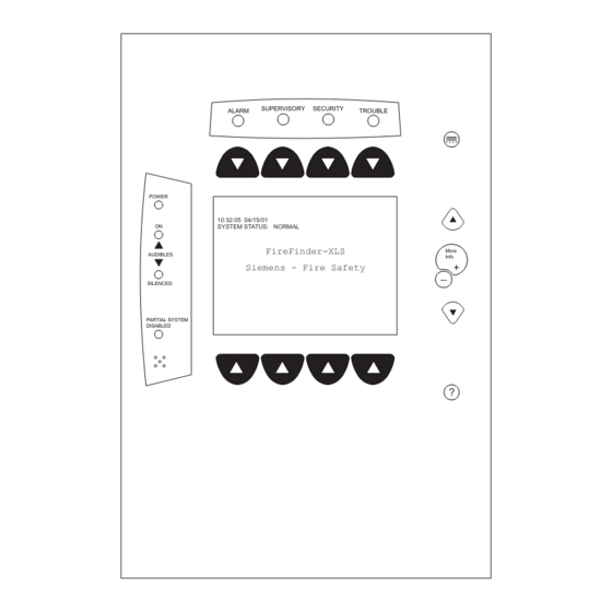
FIREFINDER-XLS CONTROL PANEL
PMI Operation Manual
SUPERVISORY
SECURITY
ALARM
TROUBLE
POWER
10:32:05 04/15/01
ON
SYSTEM STATUS: NORMAL
FireFinder-XLS
AUDIBLES
Siemens - Fire Safety
SILENCED
PARTIAL SYSTEM
DISABLED
PMI Version 1
P/N 315-033874-12
....
More
Info
+
_
?
ALARM
SUPERVISORY
TROUBLE
POWER
AUDIBLES
ON
SILENCED
PARTIAL
SYSTEM
DISABLED
CPU FAIL
PMI Version 3
ALARM SUPERVISORY SECURITY
POWER
10:32:05 04/15/11
SYSTEM STATUS: NORMAL
AUDIBLES
ON
SILENCED
FireFinder-XLS
Siemens - Fire Safety
PARTIAL SYSTEM
DISABLED
CPU FAIL
PMI Version 2
MENU
More
Info
+
ESC
?
Building T T T T T ec
Building
Building
Building
Building
TROUBLE
MENU
More
Info +
ESC
?
Siemens
Siemens Industry
Siemens
Industry
Industry, , , , , Inc.
Industry
Inc.
Inc.
Inc.
Siemens
Siemens
Industry
Inc.
ec
echnologies Di
ec
hnologies Di
hnologies Di
hnologies Division
vision
vision
vision
ec
hnologies Di
vision
Advertisement
Table of Contents

Related Manuals for Siemens FIREFINDER-XLS PMI


Summary of Contents for Siemens FIREFINDER-XLS PMI
- Page 1 POWER 10:32:05 04/15/01 SYSTEM STATUS: NORMAL POWER FireFinder-XLS More 10:32:05 04/15/11 MENU AUDIBLES Info SYSTEM STATUS: NORMAL AUDIBLES Siemens - Fire Safety SILENCED More SILENCED FireFinder-XLS Info + Siemens - Fire Safety PARTIAL SYSTEM PARTIAL SYSTEM DISABLED DISABLED CPU FAIL...
- Page 2 Cyber security disclaimer Siemens products and solutions provide security functions to ensure the secure operation of building comfort, fire safety, security management and physical security systems. The security functions on these products and solutions are important components of a comprehensive security concept.
-
Page 3: Table Of Contents
PMI OPERATION MANUAL Contents INTRODUCTION ________________________________________________________________________ 1-1 Interface Overview Using The Menu Tree Structure Physical View Geographic View Changing Views Normal Mode Menu Alert Mode Alarm Supervisory 1-11 Security 1-12 Trouble 1-12 24 Hour Trouble Resound 1-12 Reset Procedures 1-13 XNET Networked System 1-13 Global PMI... - Page 4 PMI OPERATION MANUAL Change Sensitivity 3-11 History 3-13 Activate / Deactivate 3-15 Walktest 3-16 Suggested Procedure 3-17 Initiating The Walktest 3-17 Walktesting Groups 3-19 Duration And Termination 3-19 Event Annunciation 3-20 Walktest Ending Sequence 3-21 Voice Activations 3-21 Walktest Event Log 3-22 Walktest Reports 3-22...
-
Page 5: Introduction
INTRODUCTION The PMI is the primary user interface for the FireFinder-XLS system. When the PMI is installed, the display, LEDs and control keys/buttons are visible from behind a locked door. Unlock and open the door to gain access to those keys and buttons. From the PMI the operator can acknowledge events, control the system notification appliance circuits and reset the system. -
Page 6: Interface Overview
PMI OPERATION MANUAL | CHAPTER 1 PMI-2 ΠΠSUPERVISORY SECURITY ALARM TROUBLE ALARM SUPERVISORY SECURITY TROUBLE ..Menu POWER Alarms # Supers # Securitys # Troubles # Menu Alarms # Supers # Securitys # Troubles # Scroll UP through POWER Scroll UP through... - Page 7 PMI OPERATION MANUAL CHAPTER 1 | the LCD are used for scrolling through various event queues. The navigation buttons are only selectable if the LEDs under them are lit. Only those tabs with one or more events can be selected by scrolling. A tab will blink if there are any unacknowledged events under it.
-
Page 8: Using The Menu
PMI OPERATION MANUAL | CHAPTER 1 Alert Menu USING THE MENU The menu gives you wide control of the FireFinder-XLS System. You may use the menu no matter what mode the system is in. The Main Menu items and the sub-items of the Alert, Report and Maintenance modes are shown in the FireFinder Menu Structure chart that follows. - Page 9 PMI OPERATION MANUAL CHAPTER 1 | Maintenance Menu MAINT MENU Geographical View Use More Info/+ or — (PMI-1) or ESC (PMI-2/PMI-3) ALERT MENU Physical GoTo Location to choose level: View Node Module Device Node Enter Event Use More Info/+ to get: Control Password Details...
-
Page 10: Tree Structure
PMI OPERATION MANUAL | CHAPTER 1 Tree Structure In most menus, the PMI uses a tree structure to display the elements of the system. Subordinate items connected to a device are children of that device; the device connected just above the device is its parent. This tree structure closely resembles the physical arrangement of elements used in the Zeus programming tool. -
Page 11: Normal Mode
PMI OPERATION MANUAL CHAPTER 1 | NORMAL MODE Normal mode is the absence of any off-normal conditions. The screen displays SYSTEM STATUS: NORMAL with the time and date. If a custom message has been programmed using the Zeus tool (refer to Zeus Quick Start Guide, P/N 315-033875), the node custom message also displays in this mode. - Page 12 PMI OPERATION MANUAL | CHAPTER 1 Once all events are acknowledged and audibles silenced, a Reset System soft key becomes available in the lower right side of the display. If Fire notification appliances were active, two additional soft keys become available at the bottom of the screen. These allow the operator to silence or unsilence the notification appliances (audibles).
-
Page 13: Alarm
PMI OPERATION MANUAL CHAPTER 1 | Event counts in PMI and SSDs may differ because SSDs currently display only “primitive” (individual) events, while a PMI whose devices are programmed into groups in Zeus will display only one queue event per group. In a GCNET (Global Control Network) system, each PMI can be configured to display local events or all events in the Building, but it cannot display events from different Buildings. - Page 14 PMI OPERATION MANUAL | CHAPTER 1 In addition, the System responds to alarms with other output functions (as pro- grammed in the Zeus tool) such as other audible signals. An Acknowledge Alarms soft key displays in the bottom left corner of the screen. Press this key to acknowledge each alarm and to silence the local audible.
-
Page 15: Supervisory
PMI OPERATION MANUAL CHAPTER 1 | First Floor Reception Area AREA FIRE EQUIP: ALARM LOCATION: 1st Floor Reception Area - Lobby entrance AREA CONTAINS: # Devices in ALARM: 3 ALARM TYPES: Smoke, Heat, Flow Contact: John Sample Phone #: 973.555.1234 DETAILS DEVICES BACK... -
Page 16: Security
PMI OPERATION MANUAL | CHAPTER 1 Supervisory When a supervisory is detected, the yellow Supervisory LED blinks, the System’s internal audible pulses, and the event(s) display on the screen with a blinking exclama- tion mark (!). This event listing displays the Event Custom Message, the Time of the event occurrence and the Supervisory Event Category (i.e., Security, Sprinkler, etc.). -
Page 17: 24 Hour Trouble Resound
PMI OPERATION MANUAL CHAPTER 1 | 24 Hour Trouble Resound If acknowledged troubles remain in the queue, the system will sound the local audible every 24 Hour Trouble 24 hours as a reminder. A 24 Hour Trouble Resound Resound pop-up box (See Figure 1-12) will appear on the PMI and the sounder will remain on until it is silenced. -
Page 18: Xnet Networked System
PMI OPERATION MANUAL | CHAPTER 1 XNET Networked System When the FireFinder-XLS is part of a network of FireFinder nodes communicating over the XNET communication protocol, the PMI Alert capabilities can be adjusted in several ways to provide the required level of oversight. Global PMI With the appropriate hardware upgrade and the proper configuration in the Zeus tool, a PMI can be given global capability over an XNET network of XLS, MXL and MXL-IQ... - Page 19 PMI OPERATION MANUAL CHAPTER 1 | Single Point of Control When configured for Single Point of Control in Zeus (version 12 and above), if an XLS node is granted control of the network, only that node will have Voice, Fire, and MNS control over the entire network.
-
Page 20: Report Mode
REPORT MODE Report Mode is used to obtain information and create reports about the system, modules, submodules and devices. Report Options There are four options that can be selected in the Report Mode: Configuration, Status, Queue and History. Report displays are not dynamic. The information on the PMI screen is displayed at the moment the report was requested. - Page 21 PMI OPERATION MANUAL | CHAPTER 2 The Status reports list the following information: y t i y t i i t c y t i c t i v i t y t i v i t y t i y t i v i t y t i...
- Page 22 PMI OPERATION MANUAL CHAPTER 2 | The History reports list the following information: i r c & i r c & y t i t i r ) y l i r c & i r c & i r c &...
- Page 23 PMI OPERATION MANUAL | CHAPTER 2 Menu:Report:Configuration PHY:FireFinder@1 Cust Msg Database Entity Type Usage Category Event Type Category text information Appl Rev Base Rev HW Rev FPGA Rev Cancel Figure 2-1 Configuration Report Selections To access, view and print any of the Configuration Reports, follow the directions described below.
- Page 24 PMI OPERATION MANUAL CHAPTER 2 | Menu:Report:Configuration:CustMsg:Settings PHY:FireFinder@1 None Node Module SubModule Device Cancel Figure 2-3 Report Settings Selections When the Settings have been completed, press the Apply soft key to display the status screen showing the settings that were made to generate the report. See Figure 2-4.
- Page 25 PMI OPERATION MANUAL | CHAPTER 2 Menu:Report:Configuration:CustMsg:View PHY:FireFinder@1, ZIC-4A@2 Custom Message Report Address Entity Custom Message 100% FireFinder “” ZIC-4A “ZIC-4A @ address 2” 10:53 Category text information :2-1 None “OutCkt @ address 2:1” :2-2 None “OutCkt @ address 2:2” Cancel Print GoTo...
-
Page 26: Settings
PMI OPERATION MANUAL CHAPTER 2 | Menu:Report:Status:Sensitivity PHY:FireFinder@1, DLC@1 Sensitivity Report AT: FireFinder@1, DLC@1 SETTINGS: Node: None Module: None SubModule: None Device: Smoke Cancel Settings View Figure 2-7 Sensitivity Report Settings Status Screen Press the View soft key to display the list of Detector Sensitivities. As the system reads all device sensitivities for the module/loop or device it might display the message Acquiring Data. -
Page 27: Volume Report
PMI OPERATION MANUAL | CHAPTER 2 Pressing the “Select” button switches between percentage per foot and percentage per meter. This feature applies to the DLC only. This sensitivity report can then be printed by selecting the Print option if the system has a report logging printer. -
Page 28: Queue Report
PMI OPERATION MANUAL CHAPTER 2 | The amplifier volume setting is added to each channel’s volume. The result is the volume of that channel on that amplifier. For example, if the volume on the amplifier is set to -6dB and the volume of the Convenience Page channel is -6dB, the result is a volume level of -12dB for Convenience Page on that Amplifier. - Page 29 PMI OPERATION MANUAL | CHAPTER 2 Menu:Report:Queue:Alarm:View PHY:FireFinder@1 Alarm Queue Report Address Device Event Time & 100% GROUP Building 07:07:28 May07,2002 :3-3 HFP11 07:07:28 May07,2002 2 10:53 Category text information P:3-11 HFP11 07:07:23 May07,2002 1 Cancel Print GoTo Select Figure 2-13 Report:Alarm Queue Screen #2 Menu:Report:Queue:Alarm:View PHY:FireFinder@1...
-
Page 30: History Report
PMI OPERATION MANUAL CHAPTER 2 | Press the History soft key to display the Event Log Report screen. See Figure 2-15. Menu:Report:History PHY:FireFinder@1 Event Log Report SETTINGS: List Type: All Queues Start Time: Not Set Stop Time: Not Set Records: 24 Cancel Settings View... - Page 31 PMI OPERATION MANUAL | CHAPTER 2 Enter Time/Date: 14:41:01 07/11/02 CAPS Bksp < > Cancel Done Figure 2-17 Enter Time / Date Screen When the time and date are correct, press the Done soft key. Touch the box labeled “List Type” to narrow the scope of the report. Then choose one of the following report types (See Figure 2-18): •...
- Page 32 PMI OPERATION MANUAL CHAPTER 2 | The Event Log Report screen will display the new settings. Refer to Figure 2-19. Menu:Report:History PHY:FireFinder@1 Event Log Report SETTINGS: List Type: Alarms Start Time: 12:00:00 07/12/02 Stop Time: 00:00:00 07/13/02 Records: 24 Cancel Settings View Figure 2-19...
- Page 33 PMI OPERATION MANUAL | CHAPTER 2 Menu:Report:History:View PHY:FireFinder@1 Event Log Report Address Type Time/Date 100% :3:2 Alarm 13:48:10 07/12/02 :3-3 Alarm 13:48:12 07/12/02 10:53 Category text information :3:28 Alarm 13:51:15 07/12/02 Cancel Print GoTo Select Figure 2-21 Event Log Report Screen #2 Menu:Report:History:View PHY:FireFinder@1 Event Log Report...
-
Page 34: Maintenance Mode
MAINTENANCE MODE Press the Menu button on the PMI (upper right) and select the Maintenance option by pressing the Maint soft key. Maintenance Options There are two options that can be selected in Maintenance Mode: Control and Walktest. Press the More Info button on the PMI to navigate to the desired group, loop or specific device. -
Page 35: Time / Date
PMI OPERATION MANUAL | CHAPTER 3 Enter Password: CAPS Bksp < > Cancel Done Figure 3-1 Enter Password Screen User passwords can be changed in the Zeus Programming Tool. There are five levels of passwords for PMI access, as shown in the table that follows. e l i e l i / l o... - Page 36 PMI OPERATION MANUAL CHAPTER 3 | Control - Time / Date Touch the Time/Date box to change the time and/or date. Use the keyboard screen to select the correct digits as the cursor moves along. The time is set according to the 24-hour clock.
-
Page 37: Using The Disarm Feature
PMI OPERATION MANUAL | CHAPTER 3 Using The Disarm Feature Navigate to the desired device (Physical View) or group (Geographic View) using the More Info/+ and — (PMI-1) or (PMI-2/PMI-3) buttons, select the Control option by pressing the Control soft key and then “Touch” the box labeled Disarm. The Disarm Devices screen displays showing the location. - Page 38 PMI OPERATION MANUAL CHAPTER 3 | Inputs Maint:Control:Disarm:Settings Maint:Control:Disarm:Settings PHY:FireFinder@1, DLC@1, HFP11@2 PHY:FireFinder@1, MLC@2, FP11@2 Apply To Devices Inputs Outputs Apply To Devices Inputs Outputs Categories Components Smoke/Photo Switch 1 Switch 2 Thermal Neural Cancel Cancel Figure 3-6a Figure 3-6b Disarm Inputs Settings - DLC Disarm Inputs Settings - MLC At this point, the components that were selected are not yet disarmed.
- Page 39 PMI OPERATION MANUAL | CHAPTER 3 When the device is disarmed, a trouble reports on the system indicating exactly what has been disarmed and the Partial System Disable LED glows steady yellow. When you return to the system tree in Control/Maintenance, partially disarmed modules/devices are graphically shown with the symbol in the far left column and fully disarmed devices are shown with the symbol...
-
Page 40: Using The Arm Feature
PMI OPERATION MANUAL CHAPTER 3 | Energize/De-energize In this screen you also have the option to Energize or De-energize the outputs. The Disarm Outputs status screen returns. The components that were selected are listed in the Components section of the screen (See Figures 3-10a and 3-10b.) In this example for a DLC device, the Component is Relay 1, and the Output is De-Energized. - Page 41 PMI OPERATION MANUAL | CHAPTER 3 To select individual components associated with the device, press the Settings soft key. Touch the desired Devices, Inputs or Outputs box to select it. See Figure 3-12. This screen is context-sensitive and will allow you to select only those items which are applicable.
- Page 42 PMI OPERATION MANUAL CHAPTER 3 | Outputs When the box labeled Outputs is selected for DLC devices, the components section of the screen displays the items that can be chosen. When the Outputs box is selected for MLC devices, no components are available for individual selection—if Outputs is selected, all MLC outputs are included.
-
Page 43: Asd
PMI OPERATION MANUAL | CHAPTER 3 Change ASD can only be performed at the device level (Physical view) and Bypass ASD can only be performed at the module (DLC or MLC) level. These operations will appear grayed out on the PMI when the system is set at any other level. Press the Control soft key. - Page 44 PMI OPERATION MANUAL CHAPTER 3 | Touch the box that represents the new ASD setting and press the OK soft key to select the changes. The Change ASD screen (Figure 3-18) displays to verify that the new setting has been selected. Menu:Maint:Control:ChangeASD PHY:FireFinder@1, DLC@1, HFP11@2 CHANGE ASD...
-
Page 45: Change Sensitivity
PMI OPERATION MANUAL | CHAPTER 3 level. They will also appear grayed out when an ASD setting is enabled for the device. Press the Control soft key. (If the appropriate level password has not been previously entered or if it has timed out, the Enter Password screen displays. See page 3-1.) The Control menu displays. -
Page 46: History
PMI OPERATION MANUAL CHAPTER 3 | Menu:Maint:Control:Change Sensitivity Menu:Maint:Control:Change Sensitivity PHY:FireFinder@1, DLC@1, HFP11@2 PHY:FireFinder@1, MLC@2, FP11@2 CHANGE SENSITIVITY CHANGE SENSITIVITY AT: FireFinder@1, DLC@1, HFP11@2 AT: FireFinder@1, MLC@2, FP11@2 # Sensitivity Devices: 1 # Sensitivity Devices: 1 SETTINGS: SETTINGS: FROM: Normal FROM: Normal : Low 1 : Low 1... - Page 47 PMI OPERATION MANUAL | CHAPTER 3 Control - Disable History This option can only be accessed by a user with the highest password level. Touch the box labeled Disable History to turn off the recording of History, provided that this system option has been enabled in the Zeus tool.
-
Page 48: Activate/Deactivate
PMI OPERATION MANUAL CHAPTER 3 | Activate/Deactivate To use the Activate/Deactivate feature, navigate to the desired device (Physical View) using the More Info/+ or — (PMI-1) or (PMI-2/PMI-3) buttons, select the Control option by pressing the Control soft key and then “Touch” the box labeled Activate (or Deactivate). Note that this feature is available at the Device level only and is not available in Geographic View. -
Page 49: Walktest
PMI OPERATION MANUAL | CHAPTER 3 The Activate Inputs status screen returns. See Figure 3-27 . The component that was selected is now listed in the Components section of the screen. In this example, it is Smoke/Photo. Press the Execute soft key to activate the selected component. Menu:Maint:Control:Activate PHY: FireFinder... -
Page 50: Suggested Procedure
PMI OPERATION MANUAL CHAPTER 3 | A device placed in Walktest is disconnected from its usual functions. Alarm causing devices in Walktest do NOT cause alarms until the Walktest is disabled or has timed out. A Walktest cannot be enabled if an Alarm or Supervisory exists in the system. Suggested Procedure In order to reduce the chance of problems, the following procedure must be followed before performing the Walktest. - Page 51 PMI OPERATION MANUAL | CHAPTER 3 Menu:Walktest PHY:FireFinder@1, DLC@1 WALKTEST AT: FireFinder@1, DLC@1 WALKTEST: DISABLED SETTINGS: No Bells Cancel Settings Disable Enable Figure 3-28 Walktest Status Screen Press the Settings soft key to select the Walktest bell options (Figure 3-29). Choose from No Bells (the default setting), All Bells or Group Bells (Geographic view only), then press the OK soft key.
-
Page 52: Walktesting Groups
PMI OPERATION MANUAL CHAPTER 3 | The Walktest status screen indicates the time remaining in Walktest. The time is indicated as HH:MM (hours:minutes). Menu:Walktest PHY:FireFinder@1, DLC@1 WALKTEST AT: FireFinder@1, DLC@1 WALKTEST: ENABLED SETTINGS: No Bells TIME REMAINING (HH:MM):4:00 Cancel Settings Disable Extend Figure 3-30... -
Page 53: Event Annunciation
PMI OPERATION MANUAL | CHAPTER 3 If there is no activity acknowledging Walktest events on the PMI for five minutes, the display will default to the Alert mode and the remaining time will display on the Alert mode screen. The Walktest remains in effect until the time expires or the Walktest is disabled. -
Page 54: Walktest Ending Sequence
PMI OPERATION MANUAL CHAPTER 3 | When No Bells is selected, there is no audible notification of Walktest events. There is no event-type coding during the Walktest. Audible notification is the same for Alarm, Supervisory, or any other event. If the system has a report printer, Walktest events will be printed with the Walktest designation “WT”... -
Page 55: Voice Activations
PMI OPERATION MANUAL | CHAPTER 3 Voice Activations The volume for the Walktest channel is set low. During Walktest, speaker zones are activated steady. The duration for each activation type is the same as for ZIC activation. The tone specified for Walktest is File 1 Tone 1. The user may program a tone or message to that tone location using the Zeus programming tool. - Page 56 PMI OPERATION MANUAL CHAPTER 3 | For a Walktest Report of all devices tested, press the View soft key. Press the Settings soft key to set the Start Time and Stop Time for a Walktest Report. This screen may also be used to clear the Start and Stop Times. The Walktest Report Settings screen displays, as shown in Figure 3-34.
- Page 57 PMI OPERATION MANUAL | CHAPTER 3 Menu:Report:Status:Walktest:View PHY:FireFinder@1, DLC@1 Walktest Report Address Type Custom Message 100% :1-5 Alarm 1st Flr Lobby 5 :1-6 Alarm 1st Flr Hallway 1 10:53 Category text information :1-14 Alarm 1st Flr Ladies Room 1 :1-20 Alarm 1st Flr Shipping :1-28...
-
Page 58: Other Modes
FUNCTION KEYS If Functions keys have been programmed in the Zeus tool, they can be accessed in the Menu mode by pressing the Function soft key. The Function Key status screen appears with a listing of all the functions. See Figure 4-1. To perform a desired function, highlight the function using the up and down arrow keys and then press the Execute soft key. -
Page 59: Logout Diagnostics
PMI-1 Menu Screen - Logout PMI-2/PMI-3 Menu Screen - Logout DIAGNOSTICS Diagnostics displays a series of statistics typically used by Siemens Industry, Inc. to evaluate the operation of the system. LAMP TEST Press the menu button to display the PMI Menu Screen. Next, press the Lamp Test soft key at the bottom of the screen. -
Page 60: Appendix A (Vesda Trouble Codes
VESDA TROUBLE CODES The table below lists the VESDA Trouble codes that can be reported on the PMI. Unless otherwise noted, troubles are reported from the base address of a VESDA detector or the Vscanner element of a VESDA scanner. t l u e l i t l u... - Page 61 PMI OPERATION MANUAL | APPENDIX A t l u t l u t l u u l i t l u c i l t l u e l i t l u t l u t l u t l u t l u t l u s t l...
- Page 62 PMI OPERATION MANUAL APPENDIX A | o l f o l f o l f o l f o l f o l f o l f o l f t l u u l i t l u u l i t l u u l i t l u...
- Page 63 PMI OPERATION MANUAL | APPENDIX A t l u t l u t l u t l u t l u t l u e l i t l u e l i t l u t l u t l u t l u s t l t l u...
- Page 64 PMI OPERATION MANUAL INDEX | Inde Inde x x x x x Inde Inde Inde A A A A A D D D D D Acknowledge 1-7 Database report 2-1 Acknowledge Security 1-12 Details 1-10 Acknowledge Supervisory 1-11 Diagnostics 4-2 Acknowledge Trouble 1-12 Disable History 3-14 Alarm 1-8 to 1-11...
- Page 65 PMI OPERATION MANUAL | INDEX L L L L L History 2-1, 2-3, 2-10 to 2-14 Alarm 2-3 Lamp Test 4-2 All Non-Events 2-3 LEDs 1-2 All Queues 2-3 logout 4-1 to 4-2 Security 2-3 Supervisory 2-3 M M M M M Trouble 2-3 Queue 2-1, 2-2, 2-9 to 2-14 Main menu 1-4...
- Page 66 PMI OPERATION MANUAL INDEX | Status reports 2-1, 2-2, 2-6 to 2-7 Status SW report 2-2 Supervisory 1-11 T T T T T Temperature report 2-2 Threshold report 2-2 Time / Date 3-3 touch screen 1-3 tree structure 1-6 Alert Menu 1-4 Main Menu 1-4 Maintenance Menu 1-5 Report Menu 1-4...
-
Page 67: Index
PMI OPERATION MANUAL | INDEX This page has been left intentionally blank. Index - 4... - Page 68 Siemens Industry, Inc. Siemens Canada, Ltd. P/N 315-033874-12 Building Technologies Division 1577 North Service Road East Document ID A6V10372604 Florham Park, NJ Oakville, Ontario Doc No. A5Q00071109A L6H 0H6 Canada...
Need help?
Do you have a question about the FIREFINDER-XLS PMI and is the answer not in the manual?
Questions and answers