
Related Manuals for Calorex I-PAC Series


Summary of Contents for Calorex I-PAC Series
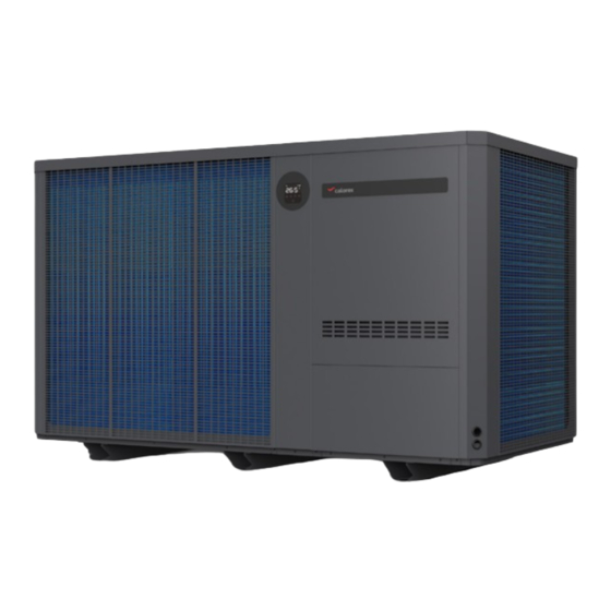
- Page 1 I-PAC inverter heat pumps I-PAC 50/100BLY, I-PAC 50/100BHC Owner Installation Manual 1007929 Issue 1...
-
Page 2: Health And Safety Warning
OWNER/INSTALLATION MANUAL HEALTH AND SAFETY WARNING This product contains electrical and rotational equipment and must be isolated electrically before removing access panels. ONLY competent trained people should work on this device. This appliance can be used by children from 8 years and above and persons with reduced physical, sensory or mental capabilities or lack of experience and knowledge if they have been given supervision or instruction... -
Page 3: Table Of Contents
CONTENTS HEALTH AND SAFETY WARNING ���������������������������2 4�0 USING YOUR HEAT PUMP �������������������������������21 1�0 INTRODUCTION ��������������������������������������������������4 4�1 THE KEY PAD ������������������������������������������������21 1�1 FOREWORD �����������������������������������������������������4 4�2 OPERATING INSTRUCTIONS �����������������������22 1�2 WARNINGS ������������������������������������������������������4 4�3 USING THE APP ��������������������������������������������23 2�0 ABOUT YOUR HEAT PUMP �������������������������������7 4�4 USING THE OPTIONAL REMOTE CONTROLLER ������������������������������������������������������29 2�1 TRANSPORTATION ����������������������������������������7... -
Page 4: 1�0 Introduction
OWNER/INSTALLATION MANUAL 1�0 INTRODUCTION 1�1 FOREWORD Thank you for choosing this product, which is designed for quiet and energy efficient operation. It is the ideal way to heat your pool in an environmentally friendly way. The WARNING sign denotes a hazard� It calls This guide provides information needed to install and attention to a procedure or practice, which if not operate the heat pump effectively. - Page 5 ACTIONS TO AVOID (OPERATION AND HANDLING): Be especially careful when handling the heat pump, not to cause any damage that may result in leakage of the cooling circuit. Do not use means to accelerate the defrosting process or to clean, other than those recommended by the manufacturer.
- Page 6 OWNER/INSTALLATION MANUAL Installation must be carried out by competent people, Refer to the user check list in section 5.2 and the error in accordance with this manual. codes listed in section 5.3 before initiating a service call. INSTALLATION: Do not attempt to interfere with any internal control settings as these have been factory calibrated and Read the instructions before installation, use and sealed.
-
Page 7: 2�0 About Your Heat Pump
2�0 ABOUT YOUR HEAT PUMP 2�1 TRANSPORTATION Always keep the heat pump upright. Undo the fixing screws on the pallet. Use a forklift to move the heat pump to the location. Do not lift the heat pump by the water inlet or outlet connections�... -
Page 8: 2�2 Accessories
OWNER/INSTALLATION MANUAL 2�2 ACCESSORIES These accessories are provided with the heat pump. 2�3 OPTIONAL ACCESSORIES The following items are additional accessories available for purchase. Remote controller kit for indoor installation. (10m extension cable). Supplied with a module to allow the Wi-Fi connectivity function to operate with the remote control. -
Page 9: 2�4 Features
2�4 FEATURES • Stepless DC inverter compressor • Brushless fan motor • EEV Technology (Electronic Equalisation Valve) • Reverse cycle defrosting with 4-way valve • High-efficiency twisted titanium heat exchanger • High pressure and low pressure protection • Soft start and wide voltage application •... -
Page 10: 3�0 Installation
OWNER/INSTALLATION MANUAL 3�0 INSTALLATION Installation must only be attempted by competent personnel. 3�1 POSITIONING AND AIRFLOW The heat pump should be fixed by M10 bolts to a level The heat pump should be located in an open concrete base or to solid mounting brackets which are space with the maximum possible distance in all securely fixed. - Page 11 I-PAC 50BLY / I-PAC 50BHC Wall Obstruction >120cm >300cm >100cm >100cm >100 cm >100cm >100cm Obstruction Typical outside inst Typical inside or plant room installation. (Not recommended for long duct runs). The plant room must not be used as an occupied space. I-PAC 100BLY / I-PAC 100BHC Obstruction Plantroom...
- Page 12 OWNER/INSTALLATION MANUAL To comply with safety regulations regarding electrical installations in wet areas the heat pump must be installed at least 350cm away from the edge of the pool or spa. Swimming pool or spa 1007929 ISSUE 1...
-
Page 13: 3�2 Pool Water Circuit
3�2 POOL WATER CIRCUIT Pool Aux heater Non return Sanitiser or (If fitted) valve chemical dosing device, (If fitted) Calorex Heat pump Anti return loop Condensate to be incorporated, water to To waste minimum height waste 100mm above heat pump outlet port (If sanitiser fitted) -
Page 14: 3�3 Plumbing
OWNER/INSTALLATION MANUAL 3�3 PLUMBING IMPORTANT Before installing the heat pump ensure the blanking disks are removed from the pool water in/out connections� These should drop out when the adaptors are unscrewed� 1. Ensure that bypass is installed and set to achieve the recommended flow rates stated in the data sheet. -
Page 15: 3�5 Electrolytic Corrosion In Swimming
3�5 ELECTROLYTIC CORROSION IN SWIMMING 3�6 ELECTRIC WIRING AND SUPPLY POOLS Electrolytic corrosion will occur when dissimilar metals All electrical work to be carried out in accordance with that are in contact with each other create a potential l.E.E. regulations, latest issue, or local codes of practice difference between themselves. -
Page 16: 3�7 Connecting The Heat Pump To The Power Supply
OWNER/INSTALLATION MANUAL 3�7 CONNECTING THE HEAT PUMP TO THE POWER SUPPLY CAUTION Remove screws and remove cover Remove Li lower two screws panel away P1 P2 R S T N POWER 380~415V 50Hz Two cable entry points Remove screws -2 and remove cover Replace all covers wi retained screws. - Page 17 Three phase Terminals in Heat Pump Electrics enclosure Pump Power terminals terminals P1 P2 Secure cables Cable clamp using cable Supply clamps and feed cord rough cable entry points in machine Isolator which disconnects all poles fitted wi in 2m and in line of sight of e heat pump Fuses/MCB...
-
Page 18: 3�8 Pool Pump Synchronisation
OWNER/INSTALLATION MANUAL 3�8 POOL PUMP SYNCHRONISATION TERMINALS P1 AND P2 *The installer will need to adjust parameter P0 when using this feature� For installations where the pool filter pump runs If the measured temperature is more than 1°C continuously, these terminals do not need to be used. from the set temperature, the point heat pump will continue to run the filter pump and heat/cool the pool. -
Page 19: 3�9 Installing The Optional Remote
3�9 INSTALLING THE OPTIONAL REMOTE CONTROLLER This optional accessory replaces the integral controller and can be installed up to10m away. Take the lid off the IPT to gain access to the existing Feed the cable from the remote controller through the controller. -
Page 20: 3�10 Remote On / Off Terminals 5 And 6
OWNER/INSTALLATION MANUAL Connect the lead. Remove the two screws from the back of the Remote Controller. Remove the appropriate knock out and fit the back of the box to the wall. Inlet for exposed cable. Inlet for concealed cable. If the cable is concealed, fit the grommet in the hole to To check that the installation is correct, set the protect the cable from rubbing. -
Page 21: 4�0 Using Your Heat Pump
4�0 USING YOUR HEAT PUMP 4�1 THE KEY PAD Symbol Designation Function 1. Power on/Off On/Off 2. Wi-Fi Setting 1. Lock/Unlock Screen Lock/Unlock 2. Heating mode (18-40°C) 3. Cooling mode (12-30°C) Heat Mode 4. Auto mode (12-40°C) 1. Boost Speed mode 2. -
Page 22: 4�2 Operating Instructions
OWNER/INSTALLATION MANUAL 4�2 OPERATING INSTRUCTIONS IMPORTANT Remember that at startup there is a 1 minute time delay before the heat pump starts a� Screen lock e� Speed Mode selection 1. Press for 3 seconds to lock or unlock the Press to switch between Boost mode screen. -
Page 23: 4�3 Using The App
4�3 USING THE APP a� APP Download b� Account registration APP Download Account Registra�on 1. Register by mobile or E-mail. Android please download from Register iOS please download from Login with Existing Acount 2. Mobile or E-mail registra�on. Obtain verification code 1007929 ISSUE 1... - Page 24 OWNER/INSTALLATION MANUAL c� Create family Create Family Please set family name and choose the room of device. Add Family Enter Family name Set location You can change room seettings anytime. d� APP Pairing APP Pairing Please make sure you are connected to the Wi-Fi. Ensure you have your SSID and Password available before attempting the pairing function.
- Page 25 2. Click "Add Device", and then follow instruc�ons to pair device. Pool Heat Pump Add Device Before pressing confirm ensure the “ ” indicator is blinking rapidly. If not repeat stages 1 and 2 on the heat pump main control panel until the indicator Xiaomi_abc…...
- Page 26 OWNER/INSTALLATION MANUAL Done 1007929 ISSUE 1...
- Page 27 Opera�on e� Operation 1. For heat pump with Hea�ng func�on only : PoolTherm Indicates the mode Boost or Whisper mode Whisper The current swimming pool water temperature The se�ng temperature Setting Timer Select Boost/ Silence Mode On/Off 2. For heat pump with Hea�ng and Cooling func�on : PoolTherm Indicates the mode Boost or Whisper mode...
- Page 28 OWNER/INSTALLATION MANUAL Share Devices to Your Family Members f� Share devices to your family members After pairing, if your family members also want to Please let your family members register the APP first, A�er pairing, if your family members also want to control the device. control the device.
-
Page 29: 4�4 Using The Optional Remote
4�4 USING THE OPTIONAL REMOTE CONTROLLER 4�5 THE KEY PAD Symbol Function Power On/Off Heating/Cooling/Auto mode Press to start Boost mode Press to start Whisper mode Temperature setting and display. 1007929 ISSUE 1... -
Page 30: 4�6 Operating Instructions
OWNER/INSTALLATION MANUAL 4�6 OPERATING INSTRUCTIONS a� Power On & Power Off c� Defrosting 1. Automatic defrosting Press to power on or power off the heat pump. When machine is defrosting, the lamp flashes; b� Temperature Setting after defrosting the lamp is illuminated. 2. -
Page 31: 5�0 Testing
5�0 TESTING Inspect the heat pump before use • Check that the fan, air inlets and outlets are not • Double check that the main power switch is off obstructed. before making checks. • It is prohibited to install refrigeration pipe or •... -
Page 32: 5�2 Protection Codes
OWNER/INSTALLATION MANUAL 5�2 PROTECTION CODES These codes indicate machine stopping due to external circumstances� These are not faults with the heat pump� Display Reason Solution No water flow through the heat pump. Check water circuit and pool pump. Check phases connected correctly (Electrician Three phase rotation protection. -
Page 33: 5�3 Fault Codes
5�3 FAULT CODES When the heat pump displays these error codes please contact your installer for advice� Display Description of fault code High pressure alarm Low pressure alarm Water outlet temp out of range alarm High exhaust temp alarm Evaporator overheat alarm (only in cooling mode) Controller communication failure Water inlet temp sensor failure Water outlet temp sensor failure... -
Page 34: 6�0 Maintenance
OWNER/INSTALLATION MANUAL 6�0 MAINTENANCE 7�0 TROUBLE SHOOTING COMMON FAULTS Isolate the power supply of the heat pump and wait 3 Minutes before cleaning, examination or repair� Cover the heat pump body when not in use. Do not attempt to work on the equipment by yourself. Improper operation may cause danger. -
Page 35: Datasheet
8�0 I-PAC 50/100BLY, I-PAC 50/100BHC DATASHEET MODEL UNITS IPT 50 BLY IPT 100 BLY IPT 50 BHC IPT 100 BHC PERFORMANCE CONDITION: Air 27°C/Water 27°C/RH 80% Heating capacity 60.2 60.2 COP range 6.6 to 15.2 6.5 to 15.0 6.6 (100% speed) 6.0 (100% speed) Average COP at 50% speed 10.5... -
Page 36: 9�0 I-Pac 50/100Bly, Performance Graphs
OWNER/INSTALLATION MANUAL 9�0 I-PAC 50/100BLY, PERFORMANCE GRAPHS IPT50BLY Hea�ng Capacity Output Capacity Output at Air 0ᵒC : 90% RH Output at Air 10ᵒC : 80% RH Output at Air 20ᵒC : 70% RH Output at Air 30ᵒC : 60% RH Electrical Input Input at Air 10ᵒC : 80% RH Water Temperature ºC... -
Page 37: 10�0 Product Drawings
10�0 PRODUCT DRAWINGS I-PAC 50BLY / I-PAC 50BHC Air inlet Fan diameter 700 inlet inlet 1100 Air outlet Water Display Mains in Water access panel 1000 Condensate Cable entry 1070 drain points 1007929 ISSUE 1... - Page 38 OWNER/INSTALLATION MANUAL I-PAC 50BLY / I-PAC 50BHC GRILLE APERTURES 1007929 ISSUE 1...
- Page 39 I-PAC 100BLY / I-PAC 100BHC 1007929 ISSUE 1...
- Page 40 OWNER/INSTALLATION MANUAL I-PAC 100BLY / I-PAC 100BHC GRILLE APERTURES 1007929 ISSUE 1...
-
Page 41: 11�0 Winterisation Procedure
11�0 WINTERISATION PROCEDURE WARNING. Isolate heat pump before opening! As heat pump embodies electrical and rotational equipment, it is recommended for your own safety that a competent person carries out the following procedure. (Drain Down Procedure) 4. Drain water from heat pump by: a) Drain valve if fitted. -
Page 42: 12�0 Warranty Conditions
OWNER/INSTALLATION MANUAL 12�0 WARRANTY CONDITIONS The following exclusions apply to the warranty given 8. The fan amps and duct pressure are outside the by Dantherm Ltd. No claims will be accepted if: specified limits. 1. The heat pump is installed in any way that is not in 9. -
Page 43: 13�0 Heat Pump Record Log
13�0 HEAT PUMP RECORD LOG In order to comply with F-Gas regulations, it is necessary for hermetically sealed systems with more than 6kg refrigerant to be leak tested annually. The operator of the heat pump is responsible for seeing that the test is carried out. A sample log sheet can be seen below. - Page 44 OWNER/INSTALLATION MANUAL Follow up actions Engineer Date Related to test on Actions taken Company Name Testing of automatic leak detection system (if fitted) Engineer Date Test result Comments Company Name Periods of non-use Name and address of company operating plant. Contact details of operator's nominated person responsible for F-Gas compliance.
-
Page 45: 14�0 Declaration Of Conformity
14�0 DECLARATION OF CONFORMITY 1007929 ISSUE 1... - Page 46 OWNER/INSTALLATION MANUAL 1007929 ISSUE 1...
- Page 47 1007929 ISSUE 1...
- Page 48 Dantherm A/S Dantherm Ltd. Dantherm GmbH Dantherm S.p.A. Marienlystvej 65 Unit 12, Galliford Road Oststraße 148 Via Gardesana 11 DK-7800 Skive Maldon CM9 4XD 22844 Norderstedt 37010 Pastrengo (VR) Denmark United Kingdom Germany Italy t. +45 96 14 37 00 t.
Need help?
Do you have a question about the I-PAC Series and is the answer not in the manual?
Questions and answers