
Related Manuals for Calorex AW631


Summary of Contents for Calorex AW631
- Page 1 Owner Installation Manual for AW631, 831, 1231, 1531 AIR/WATER HEAT PUMPS (SD526750 Issue 10) 04/11/08 Page 1...
-
Page 3: Table Of Contents
ELECTRICAL CIRCUIT DIAGRAMS ....................... 17 CONTROLS AND INDICATION LAMPS ......................19 HEAT PUMP MALFUNCTION ......................... 20 DATA SHEET ..............................21 INSTALLATION DRAWINGS .......................... 23 WINTERISING PROCEDURE ......................... 27 START UP PROCEDURE AFTER WINTERISATION..................28 WARRANTY CONDITIONS..........................29 CONTACTING CALOREX ..........................30 Page 2... -
Page 5: Air/Water Heat Pumps For Swimming Pools
AIR/WATER HEAT PUMPS FOR SWIMMING POOLS MODELS AW631, 831,1231, 1531 The Calorex ‘31’ range of air/water heat pumps is for swimming pool applications and consists of 4 models. Heat pumps in this manual are designed to heat pool water and spas within the range of 10°C to 40°C. -
Page 6: How The Heat Pump Works
HOW THE HEAT PUMP WORKS The CALOREX Swimming Pool Heat Pump provides thermodynamic heating by means of a vapour compression cycle (similar to that employed in a conventional refrigerator), in addition to operating as an active solar collector. The EVAPORATOR collects heat from the outside ambient air, pre-heated by the sun. -
Page 7: Installation
Allow adequate clearance to service panels on unit; recommend 500mm minimum. All Calorex heat pumps are by design as quiet as is practical, however due consideration should be given to siting the heat pump in order to minimise the noise coming from the machine, for example by positioning the machine so that the inlet/outlets are parallel to occupied premises. -
Page 8: Air Flow
AIR FLOW Due consideration must be given to air flow, i.e. do not obstruct inlet or outlet and ensure discharge air cannot re-circulate to inlet. (See figure 1) FIG 1 POSSIBLE POSITIONS OF A CALOREX 31 UNIT Suitable opening Suitable opening CALOREX 31 >... -
Page 9: Plumbing
See Section 4. b. The Calorex Pool Heat Pump must be connected after the filter in the return pipe to the pool. If an existing heater is being retained, then the Calorex Heat Pump should be connected between the filter and the other heater. - Page 10 h. When the pipework installation is complete the pool pump should be switched on and the system tested for leaks. Also check the filter gauge to see that there is not an excessive increase in back pressure. If everything is then working normally the water circulating system is ready to use. Water circuit to and from unit to be capable of maintaining within specified limits the rate of flow required by heat pump (see data sheet).
-
Page 11: Recommended Plumbing Schematic
RECOMMENDED PLUMBING SCHEMATIC Page 9... -
Page 12: Determining Water Flow
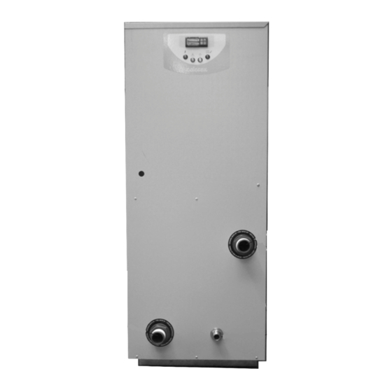
POOL WATER OUT (REMOVE BUNGS BEFORE INSTALLING MACHINE) POOL WATER IN (REMOVE BUNG CONDENSATE BEFORE DRAIN INSTALLING MACHINE) MACHINE SIDE AW631 AND AW831 FLOW RATE 115 LITRES PER MINUTE AW1231 AND AW1531 FLOW RATE 160 LITRES PER MINUTE Page 10... -
Page 13: Electrical (Machine Wiring And Supply)
All units must be correctly earthed-grounded. An earth leakage trip of the Current operating type (30mA) is recommended to be fitted to all pool electrics. INCONSISTENT ELECTRICAL SUPPLY The following limits of operation must not be exceeded if Calorex machines are to be guaranteed either in performance or warranty terms: Minimum... - Page 14 LOCATION OF ELECTRICAL SUPPLY CONNECTIONS IN 31 RANGE HEAT PUMP REMOVE THE 6 SCREWS FROM TOP COVER AND LIFT OFF ELECTRIC BOX ACCESS MAINS IN W AT ER PRE SS URE S W IT CH S O F T S T AR T ENE RGY MANAG EMENT BOTH C O N T R OL LER...
- Page 15 FIGURE 6 RECOMMENDED ELECTRICAL INSTALLATION FOR CALOREX HEAT PUMP (1Ø or 3Ø) WITH SINGLE PHASE WATER PUMP OF MAXIMUM ¾ H.P. AND ENERGY MANAGEMENT CONTROLLER SINGLE PHASE SWITCHED FUSE ISOLATOR 13AMP SUPPLY 230v WITHIN 2m OF HEAT PUMP AND FUSED TO SUIT...
- Page 16 FIGURE 8 RECOMMENDED ELECTRICAL INSTALLATION FOR CALOREX HEAT PUMP (1Ø or 3Ø) WITH THREE PHASE WATER PUMP AND ENERGY MANAGEMENT CONTROLLER THREE PHASE SINGLE PHASE SWITCHED FUSE ISOLATOR WITHIN SUPPLY TO SUIT 13 AMP SUPPLY 230v 2m OF HEAT PUMP AND SIZED IN...
- Page 17 FIGURE 9 RECOMMENDED ELECTRICAL INSTALLATION FOR CALOREX HEAT PUMP (1Ø or 3Ø) WITH SINGLE PHASE WATER PUMP OF MAXIMUM ¾ H. P (NOTE: Method shown in Fig 9. is a preferred system due to incorporated starter and interlock) SWITCHED FUSE ISOLATOR...
- Page 18 FIGURE 11 RECOMMENDED ELECTRICAL INSTALLATION FOR CALOREX HEAT PUMP(1Ø or 3Ø) WITH THREE PHASE WATER PUMP THREE PHASE SWITCHED FUSE ISOLATED WITHIN SUPPLY TO SUIT 2m OF HEAT PUMP AND SIZED IN CAPACITY OF ACCORDANCE WITH DATA SHEET WATER PUMP...
-
Page 19: Electrical Circuit Diagrams
ELECTRICAL CIRCUIT DIAGRAMS AW631, 831, 1231 AL SINGLE PHASE (230V ~ 1 N 50Hz) AW 631, 831, 1231 1531BL THREE PHASE ( 400V ~ 3 N 50Hz) Page 17... - Page 20 AW631, 831, 1231 ALY SINGLE PHASE (230V ~ 1 N 50Hz) AW 631, 831, 1231 1531BLY THREE PHASE ( 400V ~ 3 N 50Hz) Page 18...
-
Page 21: Controls And Indication Lamps
CONTROLS AND INDICATION LAMPS THERMOSTAT Adjustable digital thermostat, controls pool water temperature at the required level. Press and release key ‘P’ to display required temperature, to alter required temperature press up or down symbols. After 5 seconds display will revert to actual water temperature. NON FUNCTIONAL ON THIS APPLICATION INCREASE SET POINT DECREASE SET POINT... -
Page 22: Heat Pump Malfunction
The user check list should be carried out before initiating a service call. Do not attempt to interfere with any internal control settings as these have been factory calibrated and sealed. If in doubt or if advice required contact Calorex Service Department. Telephone (01621) 857171 or 856611... -
Page 23: Data Sheet
3) Pool water to have correct balance, pH 7.4 ± 0.4 Free Chlorine 1.0 - 3.0 ppm 4) Allow 500mm clearance to service panels 5) Calorex reserve the right to change or modify models without prior notice. 6) R407c Global warming potential (GWP) 1700. - Page 24 3) Pool water to have correct balance, pH 7.4 ± 0.4 Free Chlorine 1.0 - 3.0 ppm 4) Allow 500mm clearance to service panels 5) Calorex reserve the right to change or modify models without prior notice. 6) R407c Global Warming Potential (GWP) 1700.
-
Page 25: Installation Drawings
INSTALLATION DRAWINGS Page 23... - Page 26 Page 24...
- Page 27 Page 25...
- Page 28 Page 26...
-
Page 29: Winterising Procedure
WINTERISING PROCEDURE WARNING. Isolate machine before removing covers! The heat pump embodies electrical and rotational equipment, it is recommended for your own safety that a competent person carries out the following procedure ALL MODELS Objective To provide frost protection To eliminate corrosion problems To inhibit electrical components 1. -
Page 30: Start Up Procedure After Winterisation
START UP PROCEDURE AFTER WINTERISATION 1. Replace covers (if not fitted). 2. Remove front grille .Using a soft brush clean finned surfaces of heat pump. Replace panel. 3. Remove plastic covers on water connections and reconnect water piping or close drain valve. 4. -
Page 31: Warranty Conditions
WARRANTY CONDITIONS. The following exclusions apply to the Warranty given by Calorex Heat Pumps Ltd. No claims will be accepted if : - 1. The heat pump is incorrectly sized for the application. 2. The heat pump is installed in any way that is not in accordance with the current procedures as defined by Calorex Heat Pumps Ltd. -
Page 32: Contacting Calorex
Note:- The Reply Paid Warranty Registration Card must be returned, to ensure that the correct warranty is given. If you do not find a Registration Card with your Heat Pump please contact the Calorex Service Department giving your name, address and serial number of your heat pump. A card will be sent to you for completion.
Need help?
Do you have a question about the AW631 and is the answer not in the manual?
Questions and answers