Sign In
Upload
Download
Table of Contents
Contents
Add to my manuals
Delete from my manuals
Share
URL of this page:
HTML Link:
Bookmark this page
Add
Manual will be automatically added to "My Manuals"
Print this page
×
Bookmark added
×
Added to my manuals
Manuals
Brands
Calorex Manuals
Heat Pump
IPT 8 Series
Owners & installation manual
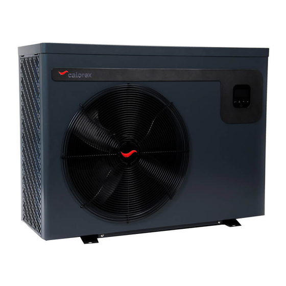
Calorex IPT 8 Series Owners & Installation Manual
I-pac / i-pac+ inverter heat pumps
Hide thumbs
1
2
3
4
5
6
7
8
9
10
11
12
13
14
15
16
17
18
19
20
21
22
23
24
25
26
27
28
29
30
31
32
33
34
35
36
37
38
39
40
41
42
43
44
page
of
44
Go
/
44
Contents
Table of Contents
Troubleshooting
Bookmarks
Table of Contents
Table of Contents
Health and Safety Warning
Table of Contents
1�0 Introduction
1�1 Foreword
1�2 Warnings
2�0 about Your Heat Pump
2�1 Transportation
2�2 Accessories
2�3 Optional Accessories
2�4 Features
2�5 Operating Conditions and Range
2�6 Operating Modes
3�0 Installation
3�1 Positioning and Airflow
3�2 Refrigerant Type and Installed
Location
3�3 Pool Water Circuit
3�4 Plumbing
3�5 Initial Checks
3�6 Electrolytic Corrosion in Swimming
Pools
3�7 Electric Wiring and Supply
3�8 Connecting the Heat Pump to the
Power Supply
3�9 Pool Pump Synchronisation
Terminals P1 and P2
3�10 Installing the Optional Remote
Controller
4�0 Using Your Heat Pump
4�1 the Key Pad
4�2 Operating Instructions
4�3 Using the App
4�4 Using the Optional Remote
Controller
4�5 the Key Pad
4�6 Operating Instructions
5�0 Testing
5�1 Heat Pump Malfunction
5�2 Protection Codes
5�3 Fault Codes
6�0 Maintenance
7�0 Trouble Shooting Common Faults
Owner/Installation Manual
8�0 Datasheets
Heating Capacity Kw
COP Range
Average COP at 50% Speed
Rated Input Power Kw
Sound Pressure Level at 10M Db(A)
9�0 Dimensions
9�1 Dimensions
10�0 Winterisation Procedure
10�1 Start up Procedure after
Winterisation
11�0 Warranty Conditions
12�0 Declaration of Conformity
Advertisement
Quick Links
1
3�7 Electric Wiring and Supply
2
4�0 Using Your Heat Pump
3
5�3 Fault Codes
Download this manual
I-PAC / I-PAC+ inverter heat pumps
IPT 8, 12, 16, 22, 28
Owner Installation Manual 1005494 Issue 3
Table of
Contents
Previous
Page
Next
Page
1
2
3
4
5
Advertisement
Chapters
Table of Contents
3
Owner/Installation Manual
36
Table of Contents
Need help?
Do you have a question about the IPT 8 Series and is the answer not in the manual?
Ask a question
Questions and answers
Related Manuals for Calorex IPT 8 Series
Heat Pump Calorex I-PAC Series Owners & Installation Manual
Inverter (28 pages)
Heat Pump Calorex I-PAC Series Owners & Installation Manual
Inverter heat pumps (48 pages)
Heat Pump Calorex IPT22 ALX Owners & Installation Manual
I-pac / i-pac+ inverter heat pumps (44 pages)
Heat Pump Calorex IPT22 ALY Owners & Installation Manual
I-pac / i-pac+ inverter heat pumps (44 pages)
Heat Pump Calorex AW631 Owners & Installation Manual
Air/water heat pumps for swimming pools (32 pages)
Heat Pump Calorex PPT8 Installation Manual
(38 pages)
Heat Pump Calorex PPT8 Technical Manual
(120 pages)
Heat Pump Calorex DIGITAL LOGIC AT800 Owner Operational Manual
(13 pages)
Heat Pump Calorex aa300 Technical Manual
(46 pages)
Heat Pump Calorex Pro-Pac 30 Technical Manual
Air/water heat pumps (24 pages)
Heat Pump Calorex VPT 12 Owners & Installation Manual
V-pac inverter heat pump (28 pages)
Heat Pump Calorex 29 Series Owners & Installation Manual
Air/water heat pumps (136 pages)
Heat Pump Calorex OTW15AX Installation Instructions Manual
(8 pages)
Heat Pump Calorex C-PAC+ CPT6 ALY Owners & Installation Manual
Swimming pool heat pumps (32 pages)
Heat Pump Calorex V-PAC VPT 12 ALX Owners & Installation Manual
Inverter heat pumps (32 pages)
Heat Pump Calorex Pro-Pac Series Owners & Installation Manual
(104 pages)
This manual is also suitable for:
Ipt 12 series
Ipt 16 series
Ipt 22 series
Ipt 28 series
Ipt8 alx
Ipt12 alx
...
Show all
Ipt16 alx
Ipt22 alx
Ipt 12 aly
Ipt16 aly
Ipt22 aly
Ipt16 bly
Ipt22 bly
Ipt28 bly
Table of Contents
Print
Rename the bookmark
Delete bookmark?
Delete from my manuals?
Login
Sign In
OR
Sign in with Facebook
Sign in with Google
Upload manual
Upload from disk
Upload from URL


Need help?
Do you have a question about the IPT 8 Series and is the answer not in the manual?
Questions and answers