Table of Contents
Advertisement
Quick Links
NuMaker-IIoT-NUC980G2D
NuMicro
®
Family
ARM926EJ-S™-based 32-bit Microprocessor
NuMaker-IIoT-NUC980G2D
User Manual
Evaluation Board for NuMicro
®
NUC980 Series
The information described in this document is the exclusive intellectual property of
Nuvoton Technology Corporation and shall not be reproduced without permission from Nuvoton.
Nuvoton is providing this document only for reference purposes of NuMicro microcontroller and
microprocessor based system design. Nuvoton assumes no responsibility for errors or omissions.
All data and specifications are subject to change without notice.
For additional information or questions, please contact: Nuvoton Technology Corporation.
www.nuvoton.com
Aug 22, 2023
Page 1 of 56
Rev 1.00
Advertisement
Table of Contents

Related Manuals for Nuvoton NuMicro NuMaker-IIoT-NUC980G2D


Summary of Contents for Nuvoton NuMicro NuMaker-IIoT-NUC980G2D
- Page 1 The information described in this document is the exclusive intellectual property of Nuvoton Technology Corporation and shall not be reproduced without permission from Nuvoton. Nuvoton is providing this document only for reference purposes of NuMicro microcontroller and microprocessor based system design. Nuvoton assumes no responsibility for errors or omissions.
-
Page 2: Table Of Contents
4.2 Rear View ........................22 5 QUICK START ....................23 5.1 Nuvoton CDC Driver Installation ................23 5.2 Nuvoton Virtual COM Driver Installation ..............25 5.3 BSP Firmware Download ................... 28 5.4 Hardware Setup ......................29 5.5 NuWriter Tool ........................ 32 5.5.1 NuWriter Setup ....................... - Page 3 NuMaker-IIoT-NUC980G2D 7.9 RMII_PE ........................48 7.10 Audio Codec and CAN_3 ..................49 7.11 SD1/eMMC1 ......................50 7.12 Arduino Uno Interface ................... 51 7.13 USB .......................... 52 7.14 Expand EBI Interface and CAN_0 ..............53 7.15 PCB Placement ...................... 54 8 REVISION HISTORY ..................55 Aug 22, 2023 Page 3 of 56 Rev 1.00...
- Page 4 NuMaker-IIoT-NUC980G2D List of Figures Figure 1-1 NuMaker-IIoT-NUC980G2 Evaluation Board ..............7 Figure 3-1 Front View of NuMaker-IIoT-NUC980G2 ..............15 Figure 3-2 Rear View of NuMaker-IIoT-NUC980G2 ..............22 Figure 4-1 CDC Driver Installation Setup ..................23 Figure 4-2 CDC Driver Installation ....................24 Figure 4-3 VCOM Driver Installation Setup ..................
- Page 5 NuMaker-IIoT-NUC980G2D List of Tables Table 4-1 Boot Source Selection Table ..................29 Aug 22, 2023 Page 5 of 56 Rev 1.00...
-
Page 6: Overview
NuMaker-IIoT-NUC980G2D OVERVIEW The NuMaker-IIoT-NUC980G2D is an evaluation board based on Arm ARM926EJ-S microprocessor NUC980DK71YC which has rich peripherals to help users to design-in their products or application systems easily. The NuMaker-IIoT-NUC980G2D consists of two parts, a NuTFT Kit Board and a NuMaker-IIoT-NUC980G2 board. - Page 7 NuMaker-IIoT-NUC980G2D Figure 1-2 NuMaker-IIoT-NUC980G2 Evaluation Board Figure 1-3 NuMaker-IIoT-NUC980G2D Evaluation Board Aug 22, 2023 Page 7 of 56 Rev 1.00...
-
Page 8: Features
NuMaker-IIoT-NUC980G2D FEATURES NuTFT Kit Board Features 16 M bits (2 MB) SPI Flash * 1 (W25Q16CV) 2.4” (320x240) LCD Panel with 4-Wire ADC Touch Function (LCD Driver is Ili9341) Five Direction Joystick * 1 Push Button * 2 ... -
Page 9: Nutft Kit Board Hardware Configuration
NuMaker-IIoT-NUC980G2D NUTFT KIT BOARD HARDWARE CONFIGURATION Front View Arduino compatible Arduino compatible interface connectors interface connectors TFT LCD Panel with TFT LCD Panel with Touch Function Touch Function Five Direction Switch Button Joystick Arduino compatible Arduino compatible interface connectors interface connectors Figure 3-1 Front View of NuTFT Kit Board Figure 3-1 shows the main components and connectors from the front side of NuTFT Kit Board. -
Page 10: Rear View
NuMaker-IIoT-NUC980G2D Rear View shows the main components and connectors from the rear side of NuTFT Kit Board. The following lists components and connectors from the rear view: 16 Mbits (2 MB) SPI Flash * 1 (W25Q16CV) (U1) Arduino UNO Compatible Interface Connectors (NU1, NU2, NU5, NU6 and NU7) ... -
Page 11: Extension Connectors
NuMaker-IIoT-NUC980G2D Extension Connectors 3.3.1 Pin Assignment for Extension Connectors NuTFT Kit Board is equipped with one SPI flash, one LCD panel with touch function, one five direction joystick and two push buttons for developing and verifying some special feature. Besides, the pin arrangement of NuTFT Kit Board is compatible with Arduino UNO. - Page 12 NuMaker-IIoT-NUC980G2D SPIFlash-CLK SPIFlash-MISO0 SPIFlash-MOSI0 3.3V SPIFlash-SS SPIFlash-MOSI1 SPIFlash-MISO1 LCM_LED Joystick-R Joystick-U Joystick-L Joystick-D Joystick-M LCM_RESET LCM_DC For NUC980 SW LCM_SPI_SS LCM_RESET LCM_SPI_CLK LCM_SPI_MISO LCM_SPI_MOSI 3.3V Figure 3-4 NuTFT Kit Board Connectors – Rear View Aug 22, 2023 Page 12 of 56 Rev 1.00...
-
Page 13: Pin Function Description
NuMaker-IIoT-NUC980G2D 3.3.2 Pin Function Description There is few different between NuMaker pin define and Arduino UNO pin define. The pin define of NU7 of Arduino is same as D11, D12, D13 (SPI function) and there is 1 set of SPI. The pin define of NU7 of NuMaker is another SPI function and there are 2 sets of SPI. - Page 14 NuMaker-IIoT-NUC980G2D Arduino UNO NuMaker-IIoT-NUC980G2 Header NuTFT Kit Board Function Pin Define Pin Define SPI Flash – MISO1 SPI Flash – MOSI1 SPI Flash – SS0 PG11 (SPI1) SPI Flash – MOSI0 RX5 (SPI0) SPI Flash – MISO0 TX5 (SPI0) SPI Flash – CLK0 PG12 (SPI0) AREF VD33_ADC...
-
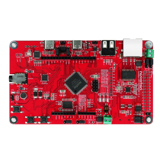
Page 15: Numaker-Iiot-Nuc980G2 Board Hardware Configuration
NuMaker-IIoT-NUC980G2D NUMAKER-IIOT-NUC980G2 BOARD HARDWARE CONFIGURATION 4.1 Front View Figure 4-1 shows the main components and connectors from the front side of NuMaker-IIoT- NUC980G2D. NAU88C22YG NUC980DK71YC USB0_ID CAN3/I²C Connector USB0 Connector VCOM Device/HOST RJ-45 USB1 HOST VCOM (Type C) (Type C) Ethernet0_PE Speaker Controller... - Page 16 NuMaker-IIoT-NUC980G2D voltage is over 5.7V or the current is over 1.7A. LED2 Green Power normal state. RTC Battery (JP15): External Battery supply for RTC 3.3V powered JP15.1: Positive (+) – JP15.2: Negative (-) – System Reset (K2): System will be reset if the K2 button is pressed ...
- Page 17 NuMaker-IIoT-NUC980G2D Connector GPIO pin of NUN980 Function NU1.1 NU1.2 VDD33 NU1.3 nRESET NU1.4 VDD33 NU1.5 NU1.6 NU1.7 NU1.8 Connector GPIO pin of NUN980 Function NU2.1 GPF7 PWM2 NU2.2 GPF8 PWM3 NU2.3 GPG11 SPI1_SS NU2.4 GPG14 SPI1_DO NU2.5 GPG13 SPI1_DI NU2.6 GPG12 SPI1_CLK NU2.7...
- Page 18 NuMaker-IIoT-NUC980G2D NU4.2 GPF10 UART1_TXD NU4.3 GPD12 UART4_TXD NU4.4 GPD13 UART4_RXD NU4.5 GPD15 I2C3_SDA NU4.6 GPD14 I2C3_SCL NU4.7 GPG6 UART5_RXD NU4.8 GPG7 UART5_TXD Connector GPIO pin of NUN980 Function NU5.1 GPD11 SPI0_DI NU5.2 VDD33 NU5.3 GPD9 SPI0_CLK NU5.4 GPD10 SPI0_DO NU5.5 NU5.6 NU5.7 GPD8...
- Page 19 NuMaker-IIoT-NUC980G2D CON11.14 GPC13 EBI_DATA13 CON11.15 GPC14 EBI_DATA14 CON11.16 GPC15 EBI_DATA15 CON11.17 GPA7 EBI_nWE CON11.18 GPA8 EBI_nRE CON11.19 GPA9 EBI_nCS0 CON11.20 GPA12 EBI_ADDR8 CON11.21 GPA11 EBI_ADDR9 CON11.22 GPA10 EBI_ADDR10 CON11.23 GPB0 ADC_AIN[0] CON11.24 GPB2 ADC_AIN[2] CON11.25 GPB4 ADC_AIN[4] CON11.26 GPB6 ADC_AIN[6] CON11.27 VDD33 CON11.28...
- Page 20 R27/R26 GPG9/GPG8 Remove with 1-bit mode Audio Codec (U11, M1, CON6, CON7, CN1): Nuvoton NAU88C22YG (U11) connects to NUC980 using I S interface Microphone (M1): Through the NAU88C22YG chip sound input – Speaker output (CON6): Through the NAU88C22YG chip sound output –...
- Page 21 NuMaker-IIoT-NUC980G2D JP2.2 CAN2_L JP13.1 CAN3_H JP13.2 CAN3_L JP10.1 EBI_DATA3 JP10.2 JP10.3 CAN0_RXD JP11.1 EBI_DATA4 JP11.2 JP11.3 CAN0_TXD JP4.1 JP4.2 PG13 JP4.3 CAN1_RXD JP5.1 JP5.2 PG14 JP5.3 CAN1_TXD JP3.1 LED_YELLOW JP3.2 JP3.3 CAN2_RXD JP12.1 EBI_DATA0 JP12.2 JP12.3 CAN2_TXD JP7.1 SDA0 JP7.2 JP7.3 CAN3_RXD JP8.1...
-
Page 22: Rear View
Serial Wired Debugger Clock CON3.4 RST# VCOM Chip Reset, Active Low. CON3.5 Power Ground Audio Codec (U11, M1, CON6, CON7, CN1): Nuvoton NAU88C22YG (U11) connects to NUC980 using I S interface Auxiliary Input and Output(CN1) – Connector Pin Name Functions CN1.1... -
Page 23: Quick Start
5.1 Nuvoton CDC Driver Installation The USB serial port function is used to print some messages on PC API, such as SecureCRT, through the standard UART protocol to help user to debug program. Download and install the latest Nuvoton CDC driver: https://www.nuvoton.com/resource-download.jsp?tp_GUID=SW1020160914071736 The installation is presented in Figure 5-1 and Figure 5-2. - Page 24 NuMaker-IIoT-NUC980G2D Figure 5-2 CDC Driver Installation Aug 22, 2023 Page 24 of 56 Rev 1.00...
-
Page 25: Nuvoton Virtual Com Driver Installation
5.2 Nuvoton Virtual COM Driver Installation The firmware programming tool NuWriter requires a NuWriter driver to be installed on PC first. Please follow the steps below to install the driver. Download and install the latest Nuvoton Virtual COM driver: https://github.com/OpenNuvoton/NUC980_NuWriter/tree/master/Driver... - Page 26 NuMaker-IIoT-NUC980G2D Aug 22, 2023 Page 26 of 56 Rev 1.00...
- Page 27 NuMaker-IIoT-NUC980G2D Figure 5-4 VCOM Driver Installation Aug 22, 2023 Page 27 of 56 Rev 1.00...
-
Page 28: Bsp Firmware Download
Linux development environment could either be native, or install in a virtual machine executed on top of other operating system. BSP download locations: Official website: https://www.nuvoton.com/products/iot-solution/iot-platform/numaker-iiot-nuc980g2d/ VMware Linux Virtual machine image An UBUNTU18.04 VMware Image with NUC980 toolchain and Buildroot –... -
Page 29: Hardware Setup
NuMaker-IIoT-NUC980G2D 5.4 Hardware Setup The NuMaker-IIoT-NUC980G2D provides jumpers to select boot-up conditions. To select USB ISP mode, the statuses of SW1.1 and SW1.2 are ON. For other boot selections, refer to Figure 5-5 and Table 5-1. Figure 5-5 Boot Source Selection Power-on setting SW1.2 SW1.1... - Page 30 NuMaker-IIoT-NUC980G2D Figure 5-6 USB-Serial Debug Port 2. Find the “Nuvoton Virtual COM Port” on the Device Manger as Figure 5-7. Figure 5-7 Device Manger 3. Open a serial port terminal, PuTTY for example, to print out debug message. Set the speed to 115200.
- Page 31 NuMaker-IIoT-NUC980G2D Figure 5-8 PuTTY Session Setting Figure 5-9 is the log after booting from SPI NAND. Figure 5-9 Booting Log Aug 22, 2023 Page 31 of 56 Rev 1.00...
-
Page 32: Nuwriter Tool
2. Connect USBD connector to the PC USB port through a USB type C cable. Figure 5-10 USBD Port 3. Boot NuMaker-IIoT-NUC980G2D from USB ISP mode. 4. Find the “WinUSB driver (Nuvoton VCOM)” on the Device Manger as Figure 5-11. Aug 22, 2023 Page 32 of 56... - Page 33 NuMaker-IIoT-NUC980G2D Figure 5-11 Device Manger(2) Power on the NuMaker-IIoT-NUC980G2D, and then open the programming tool “NuWriter.exe” on the PC. Note that the tool cannot work if the “WinUSB4NuVCOM” driver is not found. First, double-click “NuWriter.exe” on PC. NuWriter will start and a window appears. Select target chip as NUC980 series and select DDR parameter as DDR initial files.
-
Page 34: Spi Nand Mode
NuMaker-IIoT-NUC980G2D Figure 5-12 NuWriter Chip Setting NuWriter provides 7 types of images to be downloaded including DDR/SRAM, SPI, NAND, eMMC/SD, SPI NAND, PACK and Mass Production. This chapter will guide you to download images to SPI NAND flash. If you want to choose others types to download images. For more details about NUC980 Linux BSP, please refer to NUC980 NuWriter User Manual in the “BSP/Documents”... - Page 35 NuMaker-IIoT-NUC980G2D Figure 5-13 Download u-boot-spl to SPI NAND u-boot For the Linux system, Loader Type is used to boot the Linux kernel. Compile NUC980 U-Boot to get Main U-Boot and SPL U-Boot. The Main U-Boot is a fully featured version of U-Boot. In this case, the Main U-Boot need to set the address at 0x100000.
- Page 36 NuMaker-IIoT-NUC980G2D Linux 5.10 need to download the dtb into SPI NAND Flash at the specified address, depending on the value of image start offset (aligned on block size boundary, block size is based on SPI NAND specifications). If dtb start offset is equal to 0x180000, download the dtb into SPI NAND Flash at the address 0x180000.
- Page 37 NuMaker-IIoT-NUC980G2D Figure 5-16 Download uImage to SPI NAND environment Loader Type is set uboot environment variables, the image of environment type into SPI NAND Flash in the specified address. U-Boot reads environment variables file to set the environment. If image start offset is equal to 0x80000, download the image of data into SPI NAND Flash at the address 0x80000.
-
Page 38: Nutft Kit Board Schematics
NuMaker-IIoT-NUC980G2D NUTFT KIT BOARD SCHEMATICS NuTFT Kit Board Figure 6-1 shows the NuTFT Kit Board circuit. Figure 6-1 NuTFT Kit Board Circuit Aug 22, 2023 Page 38 of 56 Rev 1.00... -
Page 39: Pcb Placement
NuMaker-IIoT-NUC980G2D PCB Placement show the front and rear placement of NuTFT Kit Board. Figure 6-2 Front Placement Figure 6-3 Rear Placement Aug 22, 2023 Page 39 of 56 Rev 1.00... -
Page 40: Numaker-Iiot-Nuc980G2D Schematics
NuMaker-IIoT-NUC980G2D NUMAKER-IIOT-NUC980G2D SCHEMATICS 7.1 Block Diagram Schematic Figure 7-1 shows the Block Diagram of the NuMaker-IIoT-NUC980G2D board. Figure 7-1 NuMaker-IIoT-NUC980G2D Board Block Diagram Aug 22, 2023 Page 40 of 56 Rev 1.00... -
Page 41: Gpio List
NuMaker-IIoT-NUC980G2D 7.2 GPIO List Figure 7-2 shows the GPIO List of the NuMaker-IIoT-NUC980G2D board. Figure 7-2 GPIO List Aug 22, 2023 Page 41 of 56 Rev 1.00... -
Page 42: Power
NuMaker-IIoT-NUC980G2D 7.3 Power Figure 7-3 shows the power circuit of the NuMaker-IIoT-NUC980G2D board. Figure 7-3 Power Aug 22, 2023 Page 42 of 56 Rev 1.00... -
Page 43: Nuc980Dk
NuMaker-IIoT-NUC980G2D 7.4 NUC980DK Figure 7-4 shows the NUC980DK net name of the NuMaker-IIoT-NUC980G2D board. Figure 7-4 NUC980DK Aug 22, 2023 Page 43 of 56 Rev 1.00... -
Page 44: Power Filter
NuMaker-IIoT-NUC980G2D 7.5 Power Filter Figure 7-5 shows the power filter of the NuMaker-IIoT-NUC980G2D board. Figure 7-5 Power Filter Aug 22, 2023 Page 44 of 56 Rev 1.00... -
Page 45: Power-On Setting, Can_1 And Can_2
NuMaker-IIoT-NUC980G2D 7.6 Power-on Setting, CAN_1 and CAN_2 Figure 7-6 shows the power-on setting, CAN_1 and CAN_2 circuit of the NuMaker-IIoT-NUC980G2D board. Figure 7-6 Power-on Setting Aug 22, 2023 Page 45 of 56 Rev 1.00... -
Page 46: Nuc123Zd4An0
NuMaker-IIoT-NUC980G2D 7.7 NUC123ZD4AN0 Figure 7-7 shows the NUC123 VCOM circuit of the NuMaker-IIoT-NUC980G2D board. Figure 7-7 NUC123ZD4AN0 Aug 22, 2023 Page 46 of 56 Rev 1.00... -
Page 47: Memory
NuMaker-IIoT-NUC980G2D 7.8 Memory Figure 7-8 shows the QSPI0 (only SPI NAND Flash device mounted) circuit of the NuMaker-IIoT- NUC980G2D board. Figure 7-8 Memory Aug 22, 2023 Page 47 of 56 Rev 1.00... -
Page 48: Rmii_Pe
NuMaker-IIoT-NUC980G2D 7.9 RMII_PE Figure 7-9 shows the RMII_PE circuit of the NuMaker-IIoT-NUC980G2D board. Figure 7-9 RMII_PE Aug 22, 2023 Page 48 of 56 Rev 1.00... -
Page 49: Audio Codec And Can_3
NuMaker-IIoT-NUC980G2D 7.10 Audio Codec and CAN_3 Figure 7-10 shows the NAU88C22YG Audio Codec and CAN_3 circuit of the NuMaker-IIoT- NUC980G2D board. Figure 7-10 Audio Codec and CAN_3 Aug 22, 2023 Page 49 of 56 Rev 1.00... -
Page 50: Sd1/Emmc1
NuMaker-IIoT-NUC980G2D 7.11 SD1/eMMC1 Figure 7-11 shows the SD1 card slot circuit of the NuMaker-IIoT-NUC980G2D board. Figure 7-11 SD1/eMMC1 Aug 22, 2023 Page 50 of 56 Rev 1.00... -
Page 51: Arduino Uno Interface
NuMaker-IIoT-NUC980G2D 7.12 Arduino Uno Interface Figure 7-12 shows the Arduino Uno interface of the NuMaker-IIoT-NUC980G2D board. Figure 7-12 Arduino Uno interface Aug 22, 2023 Page 51 of 56 Rev 1.00... -
Page 52: Usb
NuMaker-IIoT-NUC980G2D 7.13 USB Figure 7-13 shows the USB 0/1 circuit of the NuMaker-IIoT-NUC980G2D board. Figure 7-13 USB Aug 22, 2023 Page 52 of 56 Rev 1.00... -
Page 53: Expand Ebi Interface And Can_0
NuMaker-IIoT-NUC980G2D 7.14 Expand EBI Interface and CAN_0 Figure 7-14 shows the Expand EBI Interface and CAN_0 circuit of the NuMaker-IIoT-NUC980G2D board. Figure 7-14 Expand EBI Interface and CAN_0 Aug 22, 2023 Page 53 of 56 Rev 1.00... -
Page 54: Pcb Placement
NuMaker-IIoT-NUC980G2D 7.15 PCB Placement Figure 7-15 and Figure 7-16 show the front and rear placement of NuMaker-IIoT-NUC980G2D. Figure 7-15 Front Placement Figure 7-16 Rear Placement Aug 22, 2023 Page 54 of 56 Rev 1.00... -
Page 55: Revision History
NuMaker-IIoT-NUC980G2D REVISION HISTORY Date Revision Description 2023.08.22 1.00 Initial version. Aug 22, 2023 Page 55 of 56 Rev 1.00... - Page 56 NuMaker-IIoT-NUC980G2D Important Notice Nuvoton Products are neither intended nor warranted for usage in systems or equipment, any malfunction or failure of which may cause loss of human life, bodily injury or severe property damage. Such applications are deemed, “Insecure Usage”.
Need help?
Do you have a question about the NuMicro NuMaker-IIoT-NUC980G2D and is the answer not in the manual?
Questions and answers