Nuvoton NuMicro Series User Manual
Arm cortex -a35-based microprocessor
Hide thumbs
Also See for NuMicro Series:
- Technical reference manual (401 pages) ,
- User manual (53 pages) ,
- Quick start manual (15 pages)
Table of Contents
Advertisement
Quick Links
NuMaker-IoT-MA35D0-A1
®
NuMicro
Family
®
®
Arm
Cortex
-A35-based Microprocessor
NuMaker-IoT-MA35D0-A1
User Manual
®
Evaluation Board for NuMicro
MA35D0 Series
The information described in this document is the exclusive intellectual property of
Nuvoton Technology Corporation and shall not be reproduced without permission from Nuvoton.
Nuvoton is providing this document only for reference purposes of NuMicro microcontroller and
microprocessor based system design. Nuvoton assumes no responsibility for errors or omissions.
All data and specifications are subject to change without notice.
For additional information or questions, please contact: Nuvoton Technology Corporation.
www.nuvoton.com
Mar. 20, 2024
Page 1 of 50
Rev 1.01
Advertisement
Table of Contents

Related Manuals for Nuvoton NuMicro Series


Summary of Contents for Nuvoton NuMicro Series
- Page 1 The information described in this document is the exclusive intellectual property of Nuvoton Technology Corporation and shall not be reproduced without permission from Nuvoton. Nuvoton is providing this document only for reference purposes of NuMicro microcontroller and microprocessor based system design. Nuvoton assumes no responsibility for errors or omissions.
-
Page 2: Table Of Contents
NuMaker-IoT-MA35D0-A1 Table of Contents 1 OVERVIEW ...................... 7 1.1 NuMaker-IoT-MA35D03F80 Board ................9 1.2 Order Number and Part Number of EVB ..............10 2 FEATURES ....................11 2.1 NuMaker-IoT-MA35D03F80 Board Features ............11 3 HARDWARE CONFIGURATION ..............12 3.1 NuMaker-IoT-MA35D03F80 Board ................12 3.1.1 Front View........................ - Page 3 NuMaker-IoT-MA35D0-A1 6.1.2 ADC and Reset Buttons Schematic ................34 6.1.3 Power-on Setting and SWJ Schematic ............... 35 6.1.4 Key buttons Schematic ....................36 6.1.5 CAN and UART CONN Schematic ................37 6.1.6 QSPI0 and NAND Flash Schematic ................38 6.1.7 SD0 Schematic ....................... 39 6.1.8 SD1 Schematic .......................
- Page 4 Figure 4-5 IP Message ........................29 Figure 4-6 Web Control Page ......................30 Figure 4-7 Remote Control LED Architecture ................30 Figure 5-1 Nuvoton Website ......................31 Figure 5-2 MA35D0 GitHub Resources ..................32 Figure 6-1 Power Input Schematic ....................33 Figure 6-2 ADC and Reset Buttons Schematic ................
- Page 5 NuMaker-IoT-MA35D0-A1 List of Tables Table 1-1 Order Number and Part Number of EVB ............... 10 Table 3-1 DDR PHY and MCP DRAM Power Voltage Selection ........... 13 Table 3-2 I2S0 (U21) Pin Function ....................14 Table 3-3 I2C0 (U21) Pin Function ....................14 Table 3-4 Audio Codec (U21) Control Pin Function...............
- Page 6 NuMaker-IoT-MA35D0-A1 Table 3-36 PN11 Pin State Control for SD1 VDD_SDIO 3.3V or 1.8V Power Voltage ....26 Table 3-37 PK9 or nRESET Pin State Control for SD1 Standard SD Card Power ON or OFF ..26 Table 4-1 Secure Boot Disable Configuration ................27 Table 4-2 SD Boot Source IO Voltage Configuration ..............
-
Page 7: Overview
NuMaker-IoT-MA35D0-A1 OVERVIEW The NuMaker-IoT-MA35D03F80 has rich peripherals such as 2 sets of 10/100 megabit Ethernet, USB2.0 high-speed host and device, 1 set of SD2.0 in Micro SD slot, 1 set of SD3.0 in SD slot, 3 sets of CAN FD, SPI, I C, UART, and 2 sets of RS-485/RS-232 serial communication ports for users to facilitate the evaluation in edge device application, such as industrial control, home appliances, new energy applications, or your creative applications. -
Page 8: Figure 1-2 Numaker-Iot-Ma35D0-A1 From Rear Side
NuMaker-IoT-MA35D0-A1 Figure 1-2 NuMaker-IoT-MA35D0-A1 from Rear Side Mar. 20, 2024 Page 8 of 50 Rev 1.01... -
Page 9: Numaker-Iot-Ma35D03F80 Board
NuMaker-IoT-MA35D0-A1 NuMaker-IoT-MA35D03F80 Board The NuMaker-IoT-MA35D03F80 has rich peripherals such as 2 sets of 10/100 megabit Ethernet, USB2.0 high-speed host and device, 1 set of SD2.0 in Micro SD slot, 1 set of SD3.0 in SD slot, 3 sets of CAN FD, SPI, I C, UART, and 2 sets of RS-485/RS-232 serial communication ports. -
Page 10: Order Number And Part Number Of Evb
NuMaker-IoT-MA35D0-A1 Order Number and Part Number of EVB The following table lists the part number of this evaluation board (EVB) based on the MA35D03F864C microprocessors, and the PCB: NuMaker-IoT-MA35D03F80 board. Order Number Part Number of EVB PCB Name NK-IMA35D0A1 NuMaker-IoT-MA35D0-A1 NuMaker-IoT-MA35D03F80 Table 1-1 Order Number and Part Number of EVB Mar. -
Page 11: Features
NuMaker-IoT-MA35D0-A1 FEATURES NuMaker-IoT-MA35D03F80 Board Features ⚫ Target Chip: MA35D03F864C (LQFP216) MCP package with DDR3L (256 MB), which can run up to 650 MHz ⚫ Power: 5V Powered by USB Type-C – Battery header for RTC power – ⚫ Debug: UART0 debug port: USB Virtual COM (VCOM) port –... -
Page 12: Hardware Configuration
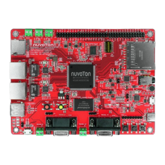
NuMaker-IoT-MA35D0-A1 HARDWARE CONFIGURATION NuMaker-IoT-MA35D03F80 Board 3.1.1 Front View Figure 3-1 shows the main components and connectors from the front side of NuMaker-IoT- MA35D03F80 board. ⚫ Target Chip (U1): MA35D03F864C (LQFP216) MCP package with DDR3L (256 MB). CAN FD Connector (J75/J2/J76) GPIO Header QSPI0 SPI NAND Flash Power-on setting... -
Page 13: Ddr Phy And Mcp Dram Power Voltage
Table 3-1 DDR PHY and MCP DRAM Power Voltage Selection 3.1.4 Audio Codec ⚫ Audio Codec Device (U21): Nuvoton NAU88C22 is audio codec device that integrates microphone input, speaker output and headphone output for audio application on this board. Mar. 20, 2024 Page 13 of 50... -
Page 14: Rmii Megabit Ethernet
NuMaker-IoT-MA35D0-A1 ⚫ Headset Jack (CON8): A headset input jack that follows CTIA definition. ⚫ Speaker Connector (J73): To connect a speaker to output audio sound. ⚫ Microphone (M1): An on-board microphone for audio sound input. Function GPIO Pin of MA35D1 Default Connected R# Conflict Function / R# Name... -
Page 15: Table 3-5 Rmii0 Pin Function
NuMaker-IoT-MA35D0-A1 RMII0_TXD0 RMII0_TXD1 RMII0_REFCLK RMII0_CRSDV RMII0_RXD0 RMII0_RXD1 RMII0_RXERR Table 3-5 RMII0 Pin Function Pin of Pin Name Note Transformer MDI-[1] To RTL8201FI (U16) MDI+[1] To RTL8201FI (U16) MDI-[0] To RTL8201FI (U16) MDI+[0] To RTL8201FI (U16) To RJ45 (CON7) To RJ45 (CON7) To RJ45 (CON7) To RJ45 (CON7) Table 3-6 Transformer (U17) Pin Function... -
Page 16: Table 3-7 Rmii1 Pin Function
NuMaker-IoT-MA35D0-A1 RMII1_MDC RMII1_MDIO RMII1_TXEN RMII1_TXD0 RMII1_TXD1 RMII1_REFCLK RMII1_CRSDV RMII1_RXD0 RMII1_RXD1 RMII1_RXERR Table 3-7 RMII1 Pin Function Pin of Pin Name Note Transformer MDI-[1] To RTL8201FI (U50) MDI+[1] To RTL8201FI (U50) MDI-[0] To RTL8201FI (U50) MDI+[0] To RTL8201FI (U50) To RJ45 (CON37) To RJ45 (CON37 To RJ45 (CON37) To RJ45 (CON37) -
Page 17: Qspi Flash
NuMaker-IoT-MA35D0-A1 3.1.6 QSPI Flash ⚫ QSPI0 Flash (U11): Winbond SPI NAND Flash (W25N04KWZEIR, 512MB) for optional booting source, supporting dual / quad mode. Pin No. Pin Name GPIO Pin of MA35D0 QSPI0_SS0 QSPI0_MISO0 QSPI0_MOSI1 QSPI0_MOSI0 QSPI0_CLK QSPI0_MISO1 QSPI0_VDD* Note *: The power group of these GPIO PD0~PD5 belongs to the VDDIO5 power domain of MA35D0 series, the default voltage of VDDIO5 (power input VDD_QSPI0) is VDD1V8 (DC 1.8V) on this NuMaker-IoT-MA35D03F80 board. -
Page 18: Usb Virtual Com (Vcom) Port
NUC123 ICE Interface (J16): The ICE interface of NUC123ZD4AN0 microcontroller (U24) for programming the internal Flash of NUC123 series MCU. The internal Flash of NUC123 series MCU had been programmed and acts as an USB VCOM device before the NuMaker-IoT- MA35D03F80 board is delivered by Nuvoton. Pin No. Pin Name Function VCOM_3.3V... -
Page 19: Table 3-13 Booting Source Qspi0 And Sd/Emmc Io Voltage Options
NuMaker-IoT-MA35D0-A1 ⚫ Options for booting source QSPI0 and SD/eMMC IO voltage selection: SW7.2 / PG1* Boot Source QSPI0 and SD/eMMC I/O Voltage 3.3V High 1.8V Note *: The GPIO PG1 is internal weakly pull-down. Table 3-13 Booting Source QSPI0 and SD/eMMC IO Voltage Options ⚫... -
Page 20: Table 3-17 Options For Sd Card 0/1 Or Emmc 0/1 Device Booting Source
NuMaker-IoT-MA35D0-A1 ⚫ Options for booting from SD0/1 card or eMMC0/1 NAND Flash memory device: SW7.7 / PG6* Boot from SD/eMMC SD0/eMMC0 Boot High SD1/eMMC1 Boot Note * : The GPIO PG6 is internal weakly pull-down. : There’s only SD0 micro card slot on this NuMaker-IoT-MA35D03F80 board. Note * Table 3-17 Options for SD Card 0/1 or eMMC 0/1 Device Booting Source SW7.8 / PG7*... -
Page 21: Reset And Rtc Wake-Up Control
NuMaker-IoT-MA35D0-A1 SW7.7 / PG6* Boot from USBH* Over-current Low-active Detect High Over-current High-active Detect Note * : The GPIO PG6 is internal weakly pull-down. Table 3-22 Over-Current High/Low-Active Detect Options for USBH Booting Source 3.1.11 Reset and RTC Wake-up Control ⚫... -
Page 22: Hs Usb2.0 Connectors
NuMaker-IoT-MA35D0-A1 JTAG_TCK / SW_CLK PG12 R370* I2S0_LRCK / R45 I2S0_MCLK / JTAG_TDO PG11 R372* SWJ_nRESET nRESET R591 Note *: No connection (NC) by default. Table 3-24 SWJ Interface (CON12) Pin Funciton 3.1.13 HS USB2.0 Connectors ⚫ USB0_ID Header (J72): Optional to pull-down the ID pin of HSUSB0 by a jumper to force HSUSB0 to always act as an USB Host. -
Page 23: Can Fd
NuMaker-IoT-MA35D0-A1 ⚫ RS485_6: The UART6 to RS485 transceiver (U43, SN65HVD11DR) and Connector (J71). Pin No. Function Name RS485_A1 RS485_B1 Table 3-26 RS485_6 connector (J71) Pin Funciton Note: UART6 can use J63 to switch functions (RS232 or RS485) ⚫ RS232_16: The UART6 to RS232 transceiver (U25, SN75C3232EDR) and Connector (CON25). Pin No. -
Page 24: Key Buttons And Leds
NuMaker-IoT-MA35D0-A1 ⚫ CAN_1: The CAN_1 transceiver (U52, TLE9351VSJ) and connector (J75). Pin No. Function Name CAN1_H CAN1_L Table 3-30 CAN_1 Header (J75) Pin Funciton ⚫ CAN_3: The CAN_3 transceiver (U53, TLE9351VSJ) and connector (J76). Pin No. Function Name CAN3_H CAN3_L Table 3-31 CAN_3 Header (J76) Pin Funciton 3.1.16 Key Buttons and LEDs... -
Page 25: Table 3-34 Sd0 Microsd Card Slot (Con34) Pin Function
NuMaker-IoT-MA35D0-A1 SD0_CLK R434 SD0_DAT0 R435 SD0_DAT1 R436 SD0_nCD PC6* R439 SD0_PWR_CTRL# PM10 R400* Note * : This pin does not belong to the SD0 Micro-SD card slot. Note * : Optional GPIO PM10 can control the power of SD0 Micro-SD card slot, but this function is disabled (R400 is NC, No Connection) by default, the power of SD0 Micro-SD card slot is always ON. -
Page 26: Table 3-35 Sd1 Standard Sd Card Slot (Con32) Pin Function
NuMaker-IoT-MA35D0-A1 Note * : The SD_LP (GPIO PN11) pin controls the VDD_SDIO power, the I/O and pull-up voltage of these SD1 group signals, to output 3.3V or 1.8V voltage. Note * : The SD_nRST (GPIO PK9) pin or nRESET signal controls the ON/OFF of VDD_SD power that feeds the fixed 3.3V to the Standard SD card slot or not. -
Page 27: Quick Start
NuMaker-IoT-MA35D0-A1 QUICK START This chapter guides users step by step to start the NuMicro MA35D0 evaluation system based on the NuMaker-IoT-MA35D03F80 board. Configure Power-on Setting Secondly, make sure the power-on setting for the booting source selection on the DIP Switch (SW7) followed the correct ON/OFF states shown in Table 4-1 ~ Table 4-4. -
Page 28: Power On The System
NuMaker-IoT-MA35D0-A1 ⚫ Options for booting source selection: SW7.4 / PG3* SW7.3 / PG2* Boot Source QSPI0 Flash Low (OFF) High (ON) SD/eMMC High NAND Flash High High Note *: These GPIO PG2 and PG3 are internal weakly pull-down. Table 4-3 SD Boot Source SD/eMMC Configuration ⚫... -
Page 29: Press The Rtc Wakeup Key Button
NuMaker-IoT-MA35D0-A1 Press the RTC Wakeup Key Button Finally, press RTC Wakeup Button (SW1) to enable the discrete power converters. Figure 4-3 RTC Wakeup Key Button (SW1) Demo Image Setting The default image of NuMaker-IoT-MA35D0-A1 launches the IoT demo application automatically. When the EVB starts up, the IoT demo application initiates a request to the router to obtain an IP address. -
Page 30: Figure 4-6 Web Control Page
NuMaker-IoT-MA35D0-A1 As shown in Figure 4-5, if the IP address obtained is 172.20.10.13, and the DHCP server is started, open the web browser and enter 172.20.10.13:3000 to launch the web control page. Figure 4-6 Web Control Page On the control web page, users can receive live updates on the device's system status, including its IP address, UID, CPU usage, memory, LEDs status, and controls. -
Page 31: Supporting Resources
Arm Cortex-A35 MPUs product line for the MA35D0 series products from the “Products” menu on Nuvoton website homepage. Figure 5-1 Nuvoton Website Software For more details about MA35D0 series software, for example, BSP (Board Support Package), Yocto, website. -
Page 32: Figure 5-2 Ma35D0 Github Resources
NuMaker-IoT-MA35D0-A1 Figure 5-2 MA35D0 GitHub Resources Mar. 20, 2024 Page 32 of 50 Rev 1.01... -
Page 33: Numaker-Iot-Ma35D0-A1 Schematics
NuMaker-IoT-MA35D0-A1 NUMAKER-IOT-MA35D0-A1 SCHEMATICS NuMaker-IoT-MA35D03F80 Schematic 6.1.1 Power Input Schematic Figure 6-1 shows the power circuit of the NuMaker-IoT-MA35D03F80 board. Figure 6-1 Power Input Schematic Mar. 20, 2024 Page 33 of 50 Rev 1.01... -
Page 34: Adc And Reset Buttons Schematic
NuMaker-IoT-MA35D0-A1 6.1.2 ADC and Reset Buttons Schematic Figure 6-2 shows the Reset buttons circuit of the NuMaker-IoT-MA35D03F80 board. Figure 6-2 ADC and Reset Buttons Schematic Mar. 20, 2024 Page 34 of 50 Rev 1.01... -
Page 35: Power-On Setting And Swj Schematic
NuMaker-IoT-MA35D0-A1 6.1.3 Power-on Setting and SWJ Schematic Figure 6-3 shows the power-on setting and SWJ circuit of the NuMaker-IoT-MA35D03F80 board. Figure 6-3 Power-on Setting and SWJ Schematic Mar. 20, 2024 Page 35 of 50 Rev 1.01... -
Page 36: Key Buttons Schematic
NuMaker-IoT-MA35D0-A1 6.1.4 Key buttons Schematic Figure 6-4 shows the key buttons circuit of the NuMaker-IoT-MA35D03F80 board. Figure 6-4 Key buttons Schematic Mar. 20, 2024 Page 36 of 50 Rev 1.01... -
Page 37: Can And Uart Conn Schematic
NuMaker-IoT-MA35D0-A1 6.1.5 CAN and UART CONN Schematic Figure 6-5 shows the CAN and UART CONN circuit of the NuMaker-IoT-MA35D03F80 board. Figure 6-5 CAN and UART CONN Schematic Mar. 20, 2024 Page 37 of 50 Rev 1.01... -
Page 38: Qspi0 And Nand Flash Schematic
NuMaker-IoT-MA35D0-A1 6.1.6 QSPI0 and NAND Flash Schematic Figure 6-6 shows the QSPI0 (only SPI NAND Flash device mounted) and NAND flash device circuit of the NuMaker-IoT-MA35D03F80 board. Figure 6-6 QSPI0 and NAND Flash Schematic Mar. 20, 2024 Page 38 of 50 Rev 1.01... -
Page 39: Sd0 Schematic
NuMaker-IoT-MA35D0-A1 6.1.7 SD0 Schematic Figure 6-7 shows the SD0 card slot circuit of the NuMaker-IoT-MA35D03F80 board. Figure 6-7 SD0 Schematic Mar. 20, 2024 Page 39 of 50 Rev 1.01... -
Page 40: Sd1 Schematic
NuMaker-IoT-MA35D0-A1 6.1.8 SD1 Schematic Figure 6-8 shows the SD1 card slot circuit of the NuMaker-IoT-MA35D03F80 board. Figure 6-8 SD1 Schematic Mar. 20, 2024 Page 40 of 50 Rev 1.01... -
Page 41: Rmii0 Schematic
NuMaker-IoT-MA35D0-A1 6.1.9 RMII0 Schematic Figure 6-9 shows the RMII0 port circuit of the NuMaker-IoT-MA35D03F80 board. Figure 6-9 RMII0 Schematic Mar. 20, 2024 Page 41 of 50 Rev 1.01... -
Page 42: Rmii1 Schematic
NuMaker-IoT-MA35D0-A1 6.1.10 RMII1 Schematic Figure 6-10 shows the RMII1 circuit of the NuMaker-IoT-MA35D03F80 board. Figure 6-10 RMII1 Schematic Mar. 20, 2024 Page 42 of 50 Rev 1.01... -
Page 43: Nau88C22 Audio Codec Schematic
NuMaker-IoT-MA35D0-A1 6.1.11 NAU88C22 Audio Codec Schematic Figure 6-11 shows the NAU88C22 audio codec circuit of the NuMaker-IoT-MA35D03F80 board. Figure 6-11 NAU88C22 Audio Codec Schematic Mar. 20, 2024 Page 43 of 50 Rev 1.01... -
Page 44: Nuc123 Vcom Schematic
NuMaker-IoT-MA35D0-A1 6.1.12 NUC123 VCOM Schematic Figure 6-12 shows the NUC123 VCOM circuit of the NuMaker-IoT-MA35D03F80 board. Figure 6-12 NUC123 VCOM Schematic Mar. 20, 2024 Page 44 of 50 Rev 1.01... -
Page 45: Hsusb 0/1 Schematic
NuMaker-IoT-MA35D0-A1 6.1.13 HSUSB 0/1 Schematic Figure 6-13 shows the HS (high speed) USB 0/1 circuit of the NuMaker-IoT-MA35D03F80 board. Figure 6-13 HSUSB 0/1 Schematic Mar. 20, 2024 Page 45 of 50 Rev 1.01... -
Page 46: Led, Rs232 And Rs485 Schematic
NuMaker-IoT-MA35D0-A1 6.1.14 LED, RS232 and RS485 Schematic Figure 6-14 shows the LED, RS232 and RS485 circuit of the NuMaker-IoT-MA35D03F80 board. Figure 6-14 LED, RS232 and RS485 Schematic Mar. 20, 2024 Page 46 of 50 Rev 1.01... -
Page 47: Pcb Placement
NuMaker-IoT-MA35D0-A1 6.1.15 PCB Placement Figure 6-15 and Figure 6-16 show the front and rear PCB component placement of the NuMaker-IoT- MA35D03F80 board. Figure 6-15 Front PCB Placement of NuMaker-IoT-MA35D03F80 Board Mar. 20, 2024 Page 47 of 50 Rev 1.01... -
Page 48: Figure 6-16 Rear Pcb Placement Of Numaker-Iot-Ma35D03F80 Board
NuMaker-IoT-MA35D0-A1 Figure 6-16 Rear PCB Placement of NuMaker-IoT-MA35D03F80 Board Mar. 20, 2024 Page 48 of 50 Rev 1.01... -
Page 49: Revision History
NuMaker-IoT-MA35D0-A1 REVISION HISTORY Date Revision Description • 2024.2.26 1.00 Initial version. • 2024.3.20 1.01 Added section 4.5 Demo Image Setting. Mar. 20, 2024 Page 49 of 50 Rev 1.01... - Page 50 NuMaker-IoT-MA35D0-A1 Important Notice Nuvoton Products are neither intended nor warranted for usage in systems or equipment, any malfunction or failure of which may cause loss of human life, bodily injury or severe property damage. Such applications are deemed, “Insecure Usage”.
Need help?
Do you have a question about the NuMicro Series and is the answer not in the manual?
Questions and answers