Table of Contents
Advertisement
Quick Links
NuMaker-IoT-MA35D1-A1
NuMicro
®
Family
Arm
Cortex
-A35-based Microprocessor
®
®
NuMaker-IoT-MA35D1-A1
User Manual
®
Evaluation Board for NuMicro
MA35D1 Series
The information described in this document is the exclusive intellectual property of
Nuvoton Technology Corporation and shall not be reproduced without permission from Nuvoton.
Nuvoton is providing this document only for reference purposes of NuMicro microcontroller and
microprocessor based system design. Nuvoton assumes no responsibility for errors or omissions.
All data and specifications are subject to change without notice.
For additional information or questions, please contact: Nuvoton Technology Corporation.
www.nuvoton.com
Sept. 25, 2023
Page 1 of 43
Rev 1.07
Advertisement
Table of Contents

Related Manuals for Nuvoton NuMaker-IoT-MA35D1-A1


Summary of Contents for Nuvoton NuMaker-IoT-MA35D1-A1
- Page 1 The information described in this document is the exclusive intellectual property of Nuvoton Technology Corporation and shall not be reproduced without permission from Nuvoton. Nuvoton is providing this document only for reference purposes of NuMicro microcontroller and microprocessor based system design. Nuvoton assumes no responsibility for errors or omissions.
-
Page 2: Table Of Contents
NuMaker-IoT-MA35D1-A1 Table of Contents 1 OVERVIEW ...................... 6 2 FEATURES ...................... 7 3 HARDWARE CONFIGURATION ..............8 3.1 Front View ........................8 3.2 Rear View ........................8 3.3 DDR PHY and MCP DRAM Power Voltage .............. 9 3.4 Audio Codec ........................9 3.5 RGMII Gigabit Ethernet .................... - Page 3 NuMaker-IoT-MA35D1-A1 5.2 Software ........................27 6 NUMAKER-IOT-MA35D1-A1 SCHEMATICS ..........29 6.1 Power Input Schematic ....................29 6.2 Key Buttons and LEDs Schematic ................30 6.3 Power-on Setting and SWJ Schematic ..............31 6.4 CCAP0 Schematic ....................... 32 6.5 CAN FD, UART and RS485 Schematic ..............33 6.6 QSPI0 and NAND Flash Schematic .................
- Page 4 Figure 6-10 NAU88C22 Audio Codec Schematic ................38 Figure 6-11 NUC123 VCOM Schematic ..................39 Figure 6-12 HSUSB 0/1 Schematic ....................40 Figure 6-13 Front PCB Placement of NuMaker-IoT-MA35D1-A1 Board ........41 Figure 6-14 Rear PCB Placement of NuMaker-IoT-MA35D1-A1 Board ........41 Sept. 25, 2023 Page 4 of 43 Rev 1.07...
- Page 5 NuMaker-IoT-MA35D1-A1 List of Tables Table 3-1 DDR PHY and MCP DRAM Power Voltage Selection ............. 9 Table 3-2 QSPI0 Flash (U11) Pin Function ................... 10 Table 3-3 NAND Flash (U12) Pin Function ..................10 Table 3-4 NUC123 ICE Interface (J9) Pin Funciton ............... 11 Table 3-5 Secure Boot Options ......................
-
Page 6: Overview
Nuvoton NuMicro MA35D1 series microprocessors (MPUs), based on MA35D16F987C (LQFP216 package, and stacking a 512 MB DDR). The NuMaker-IoT-MA35D1-A1 includes rich peripherals such as one set of Gigabit Ethernet, one set of Megabit Ethernet, high-speed USB2.0 Host and device, one set of SD2.0 in Micro SD slot, one set of CAN FD, and RS-485 and RS232 serial communication ports. -
Page 7: Features
NuMaker-IoT-MA35D1-A1 FEATURES Target Chip: MA35D16F987C (LQFP216) MCP package with DDR3L (512 MB), which can run up to 800 MHz Power: 5V/2A Power Jack, USB VCOM Port or HSUSB0 Device – Battery header for RTC power – Debug: UART0 debug port: USB Virtual COM (VCOM) port –... -
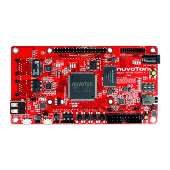
Page 8: Hardware Configuration
Header (U18, NAU88C22) Header (J3) (U7, J2) (U9, J6) Figure 3-1 Front View of NuMaker-IoT-MA35D1-A1 Rear View Figure 3-2 shows the main components and connectors from the rear side of NuMaker-IoT-MA35D1-A1 board. RGMII0 RJ45 Connector (CON6) RMII1 RJ45 Micro-SD Connector... -
Page 9: Ddr Phy And Mcp Dram Power Voltage
MA35D16F787C / DDR2 Note * : Only one resistor R252 or R253 can be mounted on the PCB and user should make sure which part number chip of MA35D1 series that be mounted on the this NuMaker-IoT-MA35D1-A1 board. Note * : By default, only R252 resistor and MA35D16F987C target chip are mounted on the NuMaker- IoT-MA35D1-A1 board. -
Page 10: Nand Flash
Note *: The power group of these GPIO PD0~PD5 belongs to the VDDIO5 power domain of MA35D1 series, the default voltage of VDDIO5 (power input VDD_QSPI0) is VDD1V8 (DC 1.8V) on this NuMaker-IoT-MA35D1-A1 board. Table 3-2 QSPI0 Flash (U11) Pin Function NAND Flash ... -
Page 11: Power Jack
3.11 Power-on Setting Power-on Setting DIP Switch (SW7): The GPIO PG0, PG1, PG2, PG3, PG4, PG5, PG6 and PG7 determine how to boot the evaluation environment on the NuMaker-IoT-MA35D1-A1 board. These GPIO pins are internal weakly pull-down. Options for secure boot enable or disable: SW7.1 / PG0*... -
Page 12: Table 3-7 Booting Source Options
High High Note * : These GPIO PG2 and PG3 are internal weakly pull-down. : There’s only SD1 micro card slot on this NuMaker-IoT-MA35D1-A1 board. Note * Table 3-7 Booting Source Options Options for booting from NAND Flash device: SW7.6 / PG5*... -
Page 13: Table 3-11 4/8-Bit Options For Emmc Nand Flash Device Booting Source
High eMMC 8-bit Booting* Note * : The GPIO PG7 is internal weakly pull-down. : There’s no eMMC1 NAND Flash memory device on this NuMaker-IoT-MA35D1-A1 board. Note * Table 3-11 4/8-bit Options for eMMC NAND Flash Device Booting Source ... -
Page 14: Reset And Rtc Wake-Up Control
: This RTC_RPWR output pin of MA35D1 is wired directly to these EN input pins of the discrete power IC devices (U2~U6) on this NuMaker-IoT-MA35D1-A1 board by default. (Only the R250 resistor is mounted on board, but both R189 and R210 are unmounted) -
Page 15: Hs Usb2.0 Connectors
J10 connector to force the ID pin of HSUSB0 at low state. HSUSB1 Host (CON11, USB Type-A Receptacle): HSUSB1 for USB Host with type-A connector. Note: USB power switch device (U22) had removed on NuMaker-IoT-MA35D1-A1 board in V2.4. 3.15 RS232 or UART ... -
Page 16: Can Fd
NuMaker-IoT-MA35D1-A1 Table 3-18 RS232_10 Header (J5) Pin Funciton (V2.3) UART_10 Header (J5, new funtion definitions in V2.4): The UART10 header (J5). Note: RS232 transceiver (U8) had removed on NuMaker-IoT-MA35D1-A1 board in V2.4. Pin No. Function Name UART10_TXD UART10_RXD UART10_nCTS UART10_nRTS Table 3-19 UART_10 Header (J5) Pin Funciton (V2.4) - Page 17 NuMaker-IoT-MA35D1-A1 I2C5_SDA VDD5V* I2C5_SCL PN15 PH15 UART14_TXD PH14 UART14_RXD PI13 PI14 PI15 VDD3V3 PL14 SPI0_MOSI PL15 SPI0_MISO SPI0_CLK SPI0_SS0 SPI0_SS1 I2C4_SDA I2C4_SCL PI10 PI11 Sept. 25, 2023 Page 17 of 43 Rev 1.07...
-
Page 18: Key Buttons And Leds
PI12 Note *: For more accurate DC 5V power, please make sure the 5V/2A adapter is plugged-in the Power Jack (CON2) to supply the power to this NuMaker-IoT-MA35D1-A1 board. Table 3-22 Raspberry Pi 40-pin Connector (CON4) Pin Funciton Figure 3-3 shows the UART, RS485, CAN headers and Raspberry Pi connector. -
Page 19: Cmos Sensor Capture Connector
NuMaker-IoT-MA35D1-A1 KEY_1 VDD3V3 KEY_2 PN12 VDD3V3 KEY_3 PN13 VDD3V3 Table 3-23 Key Buttons (KEY_0, KEY_1, KEY_2, KEY_3) Pin Function User Indication LEDs (LED_0, LED_1, LED_2): LED_# Function / Color GPIO pin of MA35D1 LED_0 LEDR1 / Red LED_1 LEDG1 / Green... -
Page 20: Microsd Card Slot
NuMaker-IoT-MA35D1-A1 CCAP0_nRST CCAP0_I2C2_SCL CCAP0_I2C2_SDA VDD3V3 VDD3V3 Table 3-25 CCAP0 Connector (CON3) Pin Funciton 3.21 MicroSD Card Slot SD1 MicroSD Card Slot (CON5): Supports SD1 (SD3.0) for optional system booting. Pin No. Pin Name GPIO pin of MA35D1 Default Connected R#... -
Page 21: Arduino Uno Compatible Extension Connectors
NuMaker-IoT-MA35D1-A1 3.3V High 1.8V Table 3-27 PN11 Pin State Control for SD1 VDD_SDIO 3.3V or 1.8V Power Voltage SD1 MicroSD Card Power (VDD_SD) ON/OFF Control: The GPIO PN14 pin or nRESET signal controls the ON/OFF of VDD_SD power that feeds to the MicroSD card slot. -
Page 22: Table 3-29 Arduino Uno Interface Connector 1 (Nu1) Pin Funciton
VDD5V* Note *: For more accurate DC 5V power, please make sure the 5V/2A adapter is plugged-in the Power Jack (CON2) to supply the power to this NuMaker-IoT-MA35D1-A1 board. Table 3-29 Arduino UNO Interface Connector 1 (NU1) Pin Funciton ... -
Page 23: Table 3-32 Arduino Uno Interface Connector 4 (Nu4) Pin Funciton
NuMaker-IoT-MA35D1-A1 PD10 PD11 PG10 VREF VDD3V3 I2C_SDA I2C_SCL Table 3-32 Arduino UNO Interface Connector 4 (NU4) Pin Funciton Sept. 25, 2023 Page 23 of 43 Rev 1.07... -
Page 24: Quick Start
QUICK START This chapter guides users step by step to start the NuMicro MA35D1 evaluation system based on the NuMaker-IoT-MA35D1-A1 board. Configure Power-on Setting Secondly, make sure the power-on setting for the booting source selection on the DIP Switch (SW7) followed the correct ON/OFF states shown in Table 4-1 ~ Table 4-4. -
Page 25: Power On The System
NuMaker-IoT-MA35D1-A1 Low (OFF) Low (OFF) QSPI0 Flash High SD/eMMC High NAND Flash High High Note *: These GPIO PG2 and PG3 are internal weakly pull-down. Table 4-3 QSPI0 Boot Source Configuration Options for booting from QSPI0 Flash device: SW7.8 / PG7* SW7.7 / PG6*... -
Page 26: Figure 4-3 Rtc Wakeup Key Button (Sw1)
NuMaker-IoT-MA35D1-A1 Finally, press RTC Wakeup Button (SW1) to enable the discrete power converters. Figure 4-3 RTC Wakeup Key Button (SW1) Sept. 25, 2023 Page 26 of 43 Rev 1.07... -
Page 27: Supporting Resources
Arm Cortex-A35 MPUs product line for the MA35D1 series products from the “Products” menu on Nuvoton website homepage. Figure 5-1 Nuvoton Website Software For more details about MA35D1 series software, for example, BSP (Board Support Package), Yocto, website. -
Page 28: Figure 5-2 Ma35D1 Github Resources
NuMaker-IoT-MA35D1-A1 9. MA35D1 · Yocto · · Buildroot · · TF-A · · OP-TEE · · U-Boot · · Linux-5.4.y · · Linux-5.10.y · · Linux Applications · · RTP · · OpenWrt · · NuWritter · · Docker ·... -
Page 29: Numaker-Iot-Ma35D1-A1 Schematics
NuMaker-IoT-MA35D1-A1 NUMAKER-IOT-MA35D1-A1 SCHEMATICS Power Input Schematic Figure 6-1 shows the power circuit of the NuMaker-IoT-MA35D1-A1 board. R215 0 (NC) 5 V I N SY SPWR_EN R0402 SY SPWR_EN R216 0 (NC) N123_USB5V CON2 R0402 N123_USB5V 5VIN VDD5V DC-PLUG(2.0) USBD_USB5V SS24A... -
Page 30: Key Buttons And Leds Schematic
NuMaker-IoT-MA35D1-A1 Key Buttons and LEDs Schematic Figure 6-2 shows the key buttons and LEDs circuit of the NuMaker-IoT-MA35D1-A1 board. nRESET/HSUSB0_ID,VBUSVLD/HSUSBH_PWREN,OVC/PWM_0/UART_7,14/CAN_1/SPI_0/SC_1/I2C_2/INT_0,2 nRESET nRESET/WDT_nRST HSUSB0_ID HSUSB0_ID PF15 HSUSB0_VBUSVLD PF15/HSUSB0_VBUSVLD R e s e t VDD3V3 PL12 HSUSBH_PWREN PL12/EPWM0_SY NC_IN/UART7_nCTS/ECAP1_IC0/UART14_RXD/SPI0_SS0/I2S1_LRCK/SC1_CLK/EBI_AD0/HSUSBH_PWREN/I2C2_SDA/TM0/EPWM0_CH2/EBI_AD11/RGMII0_PPS/RMII0_PPS PL13 HSUSBH_OVC PL13/EPWM0_SY NC_OUT/UART7_nRTS/ECAP1_IC1/UART14_TXD/SPI0_CLK/I2S1_BCLK/SC1_DAT/EBI_AD1/HSUSBH_OVC/I2C2_SCL/TM0_EXT/EPWM0_CH3/EBI_AD12/RMII1_PPS... -
Page 31: Power-On Setting And Swj Schematic
NuMaker-IoT-MA35D1-A1 Power-on Setting and SWJ Schematic Figure 6-3 shows the power-on setting and SWJ circuit of the NuMaker-IoT-MA35D1-A1 board Power-on Setting NAND/UART_1,2,3,4,5,8,16 NAND_DATA0 PA0/UART1_nCTS/UART16_RXD/NAND_DATA0/EBI_AD0/EBI_ADR0 NAND_DATA1 Secure Boot PA1/UART1_nRTS/UART16_TXD/NAND_DATA1/EBI_AD1/EBI_ADR1 NAND_DATA2 Secure Boot Enable VDD3V3 PA2/UART1_RXD/NAND_DATA2/EBI_AD2/EBI_ADR2 NAND_DATA3 Secure Boot Disable PA3/UART1_TXD/NAND_DATA3/EBI_AD3/EBI_ADR3 NAND_DATA4... -
Page 32: Ccap0 Schematic
NuMaker-IoT-MA35D1-A1 CCAP0 Schematic Figure 6-4 shows the CCAP0 connector circuit of the NuMaker-IoT-MA35D1-A1 board. CCAP0 Connector CCAP0_SCLK C0_SCLK PK9/I2C3_SCL/CCAP0_SCLK/EBI_AD0/EBI_ADR0 PK10 CCAP0_PIXCLK R0603 PK10/CAN1_RXD/CCAP0_PIXCLK/EBI_AD1/EBI_ADR1 PK11 CCAP0_HSY NC PK11/CAN1_TXD/CCAP0_HSY NC/EBI_AD2/EBI_ADR2 CCAP0_VSY NC PM0/I2C4_SDA/CCAP0_VSY NC/EBI_AD3/EBI_ADR3 CCAP0_nRST C0603 PM1/I2C4_SCL/SPI3_I2SMCLK/CCAP0_SFIELD/EBI_AD4/EBI_ADR4 CCAP0_DATA0 PM2/CAN3_RXD/CCAP0_DATA0/EBI_AD5/EBI_ADR5 CCAP0_DATA1 VDD3V3 VDD3V3... -
Page 33: Can Fd, Uart And Rs485 Schematic
NuMaker-IoT-MA35D1-A1 CAN FD, UART and RS485 Schematic Figure 6-5 shows the CAN FD, UART and RS485 circuit of the NuMaker-IoT-MA35D1-A1 board. CAN_1 VDD5V VDD3V3 SPI2_SS0 AR_D10 PG8/EPWM1_CH4/UART12_RXD/CAN3_RXD/SPI2_SS0/LCM_VSY NC/LCM_MPU_RD/EN/I2C3_SDA/EBI_AD7/EBI_nCS0 SPI2_CLK AR_D13 R263 PG9/EPWM1_CH5/UART12_TXD/CAN3_TXD/SPI2_CLK/LCM_HSY NC/LCM_MPU_WR/RW/I2C3_SCL/EBI_AD8/EBI_nCS1 PG10 SPI2_MOSI AR_D11 PG10/UART12_nRTS/UART13_TXD/SPI2_MOSI/LCM_CLK/EBI_AD9/EBI_nWRH SPI2_MISO AR_D12 R261... -
Page 34: Qspi0 And Nand Flash Schematic
NuMaker-IoT-MA35D1-A1 QSPI0 and NAND Flash Schematic Figure 6-6 shows the QSPI0 (only SPI NAND flash device mounted) and NAND flash device circuit of the NuMaker-IoT-MA35D1-A1 board QSPI0_Flash VDD_QSPI0 R255 33 R0402 QSPI0_SS0 PD0/UART3_nCTS/UART4_RXD/QSPI0_SS0 PD1/UART3_nRTS/UART4_TXD/QSPI0_CLK R257 33 R0402 QSPI0_MOSI0 R0603 R0603... -
Page 35: Sd1 Schematic
SD1 Schematic Figure 6-7 shows the SD1 card slot circuit of the NuMaker-IoT-MA35D1-A1 board. N o t e : I f t h e s e P J 6 ~ P J 1 1 p i n s ( e M M C 1 _ x x x ) -
Page 36: Rgmii0_Pe Schematic
NuMaker-IoT-MA35D1-A1 RGMII0_PE Schematic Figure 6-8 shows the RGMII0 PE port circuit of the NuMaker-IoT-MA35D1-A1 board. 4.7K RGMII0_RXD2 4.7K (NC) E_DVDDRG CCAP_1 RGMII0_MDC R0402 R0402 PE0/UART9_nCTS/UART8_RXD/CCAP1_DATA0/RGMII0_MDC/RMII0_MDC Pu l l -u p to d i sa b l e PL L @AL D PS m o d e... -
Page 37: Rmii1_Pf Schematic
NuMaker-IoT-MA35D1-A1 RMII1_PF Schematic Figure 6-9 shows the RMII1 PF port circuit of the NuMaker-IoT-MA35D1-A1 board. RMII1_MDC PF0/UART2_nCTS/UART1_RXD/RGMII0_RXD3/RMII1_MDC/KPI_COL0 RMII1_MDIO PF1/UART2_nRTS/UART1_TXD/RGMII0_TXCLK/RMII1_MDIO/KPI_COL1 RMII1_TXEN PF2/UART2_RXD/RGMII0_TXD2/RMII1_TXEN/KPI_COL2 RMII1_TXD0 PF3/UART2_TXD/RGMII0_TXD3/RMII1_TXD0/KPI_COL3 RMII1_TXD1 PF4/UART11_nCTS/UART10_RXD/I2S0_LRCK/SPI1_SS0/RMII1_TXD1/CAN2_RXD/KPI_ROW0 RMII1_REFCLK PF5/UART11_nRTS/UART10_TXD/I2S0_BCLK/SPI1_CLK/RMII1_REFCLK/CAN2_TXD/KPI_ROW1 RMII1_CRSDV PF6/UART11_RXD/I2S0_DI/SPI1_MOSI/RMII1_CRSDV/I2C4_SDA/SC0_CLK/KPI_ROW2 RMII1_RXD0 PF7/UART11_TXD/I2S0_DO/SPI1_MISO/RMII1_RXD0/I2C4_SCL/SC0_DAT/KPI_ROW3 RMII1_RXD1 PF8/UART13_RXD/I2C5_SDA/SPI0_SS0/RMII1_RXD1/SC0_RST/KPI_COL4 RMII1_RXERR PF9/UART13_TXD/I2C5_SCL/SPI0_SS1/RMII1_RXERR/SC0_PWR/KPI_COL5 RMII_1/UART_1,2,10,11,13/I2C_5/SPI_1/SC_0/CAN_2/KPI F_VDD3V3 VDDIO9 Note: The VDDIO9 is the input voltage of I/O... -
Page 38: Nau88C22 Audio Codec Schematic
NuMaker-IoT-MA35D1-A1 6.10 NAU88C22 Audio Codec Schematic Figure 6-10 shows the NAU88C22 audio codec circuit of the NuMaker-IoT-MA35D1-A1 board. Codec AUDIO_D3V3 VDD3V3 AUDIO_3V3 SPK_3V3 AUDIO_3V3 R133 R134 R0603 R0603 C168 C169 C170 C167 0.1u VSSA SPK_3V3 10uF 10uF 10uF C0603 Speaker... -
Page 39: Nuc123 Vcom Schematic
NuMaker-IoT-MA35D1-A1 6.11 NUC123 VCOM Schematic Figure 6-11 shows the NUC123 VCOM circuit of the NuMaker-IoT-MA35D1-A1 board. PE[15:14] PE[15:14] N123_USB5V N123_USB5V VDD3V3 VDD3V3 T5 VCOM_3V3 (NC) NUC123 VCOM VDD3V3 VCOM_3V3 C185 10uF C0603 VCOM_3V3 VCOM_3V3 R157 AVDD SPI0_CS0/PC.0 SPI2_CLK/PD.1 SPI0_CLK/PC.1 MISO2_0/PD.2 MISO0_0/PC.2... -
Page 40: Hsusb 0/1 Schematic
NuMaker-IoT-MA35D1-A1 6.12 HSUSB 0/1 Schematic Figure 6-12 shows the HS (high speed) USB 0/1 circuit of the NuMaker-IoT-MA35D1-A1 board. USB0 HSUSB0_D+ PF15 HSUSB0_D+ PF15 HSUSB0_D- HSUSB0_D- PL[13:12] (Device/HOST) PL[13:12] VDD_HSUSB0 VDD3V3 VDD_HSUSB0 HSUSB0_ID HSUSB0_ID USB1(HOST) HSUSB1_D+ C195 C196 HSUSB1_D+ HSUSB1_D- 0.1u... -
Page 41: Pcb Placement
6.13 PCB Placement Figure 6-13 and Figure 6-14 show the front and rear PCB component placement of the NuMaker-IoT- MA35D1-A1 board. Figure 6-13 Front PCB Placement of NuMaker-IoT-MA35D1-A1 Board Figure 6-14 Rear PCB Placement of NuMaker-IoT-MA35D1-A1 Board Sept. 25, 2023 Page 41 of 43 Rev 1.07... -
Page 42: Revision History
NuMaker-IoT-MA35D1-A1 REVISION HISTORY Date Revision Description · 2022.10. 6 1.00 Initial version. · Updated Figure 1-1, Figure 3-1, Figure 3-2, Figure 5-2, and Figure 6-1. 2022.10.31 1.01 · Updated the options about USB booting source in section 3.11. · Updated the pictures in Figure 1-1, Figure 3-1, Figure 3-2, Figure 3-3, Figure 3-4, Figure 6-13 and Figure 6-14. - Page 43 NuMaker-IoT-MA35D1-A1 Important Notice Nuvoton Products are neither intended nor warranted for usage in systems or equipment, any malfunction or failure of which may cause loss of human life, bodily injury or severe property damage. Such applications are deemed, “Insecure Usage”.
Need help?
Do you have a question about the NuMaker-IoT-MA35D1-A1 and is the answer not in the manual?
Questions and answers