Table of Contents
Advertisement
Quick Links
NuMaker-IoT-M2354
NuMicro
®
Family
Arm
®
32-bit Cortex
®
-M23 Microcontroller
NuMaker-IoT-M2354U
NuMaker-IoT-M2354C
User Manual
Evaluation Board for NuMicro
®
M2354 Series
The information described in this document is the exclusive intellectual property of
Nuvoton Technology Corporation and shall not be reproduced without permission from Nuvoton.
Nuvoton is providing this document only for reference purposes of NuMicro microcontroller and
microprocessor based system design. Nuvoton assumes no responsibility for errors or omissions.
All data and specifications are subject to change without notice.
For additional information or questions, please contact: Nuvoton Technology Corporation.
www.nuvoton.com
Jul. 16, 2021
Page 1 of 54
Rev 1.00
Advertisement
Table of Contents

Related Manuals for Nuvoton NuMaker-IoT-M2354U


Summary of Contents for Nuvoton NuMaker-IoT-M2354U
- Page 1 The information described in this document is the exclusive intellectual property of Nuvoton Technology Corporation and shall not be reproduced without permission from Nuvoton. Nuvoton is providing this document only for reference purposes of NuMicro microcontroller and microprocessor based system design. Nuvoton assumes no responsibility for errors or omissions.
-
Page 2: Table Of Contents
COM/SEG LCD interface and HTN-LCD Panel .........25 Nu-Link2-Me ..................26 VCOM Switches ..................26 3.14.1 Status LEDs ..................26 3.14.2 Quick Start ................27 Toolchains Support ................27 Nuvoton Nu-Link Driver Installation ............27 Jul. 16, 2021 Page 2 of 54 Rev 1.00... - Page 3 NuMaker-IoT-M2354 BSP Firmware Download ..............29 Hardware Setup ................29 Finding the Example Project ...............31 Executing the Project under Toolchains ..........31 Keil MDK ..................... 31 4.6.1 IAR EWARM ..................34 4.6.2 NuEclipse .................... 36 4.6.3 NuMaker-IOT-M2354 Schematics ............ 42 Nu-Link2-Me ..................42 M2354 target Board .................43 Arduino UNO Compatible Interface ............44 Wi-Fi Module .................45 LoRa Module .................46...
- Page 4 NuMaker-IoT-M2354 List of Figures Figure 1-1 NuMaker-IoT-M2354 Evaluation Board ................7 Figure 3-1 Front View of NuMaker-IoT-M2354 ................9 Figure 3-2 Rear View of NuMaker-IoT-M2354 ................11 Figure 3-3 Arduino UNO Compatible Extension Connectors ............12 Figure 3-4 External Power Supply Sources on Nu-Link2-Me ............18 Figure 3-5 External Power Supply Sources on M2354 target board ..........
- Page 5 NuMaker-IoT-M2354 Figure 5-1 Nu-Link2-Me Circuit ...................... 42 Figure 5-2 M2354 Platform Circuit ....................43 Figure 5-3 Arduino UNO Compatible Interface ................44 Figure 5-4 Wi-Fi Module Circuit ..................... 45 Figure 5-5 LoRa Module Circuit ..................... 46 Figure 5-6 on-board sensors Circuit ....................47 Figure 5-7 CAN and RS485 Connector Circuit ................
- Page 6 NuMaker-IoT-M2354 List of Tables Table 3-1 Extension Connectors ....................12 Table 3-2 Arduino UNO Extension Connectors and M2354KJFAE Mapping GPIO List ....13 Table 3-3 mikroBUS Mapping with M2354KJFAE ................. 14 Table 3-4 On-board Modules, Sensors, Connectors and M2354KJFAE GPIO Function List ..15 Table 3-5 Vin Power Source ......................
-
Page 7: Overview
NuMaker-IoT-M2354 OVERVIEW The NuMaker-IoT-M2354 is an evaluation board for Nuvoton NuMicro M2354 microcontrollers. The NuMaker-IoT-M2354 consists of two parts, a M2354 target board and an on-board Nu-Link2-Me debugger and programmer. The NuMaker-IoT-M2354 is designed for secure IoT application, prototype development and validation with power consumption monitoring function. -
Page 8: Features
8COM/40SEG LCD with panel Environmental sensor: BME680 Wi-Fi module LoRa module: NuMaker-IoT-M2354U for 915 MHz – NuMaker-IoT-M2354C for 433 MHz – Ammeter connector for measuring the microcontroller’s power consumption Flexible board power supply: External V power connector –... -
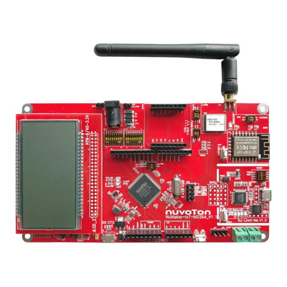
Page 9: Hardware Configuration
NuMaker-IoT-M2354 HARDWARE CONFIGURATION Front View mikro BUS Pin switch mikroBUS connector LCD Pin switch External 5V Power Connector LoRa Antenna External Power Jack LoRa Module: SX1276 External GND Connector LoRa Power LED M2354 Target Board Wi-Fi Module FW Update Switch External V Connector DDIO... - Page 10 NuMaker-IoT-M2354 Antenna Connector (J10) – COM/SEG LCD interface (JLCD_1) and LCD panel (JLCD_2) LCD pin switch (S2) – Environmental sensor: BME680 (U11) mikroBUS connector (MBUS1) mikroBUS pin switch (S1) – CAN Connector (CAN0 and JP7) RS485 Connector (RS485 and JP8) ...
-
Page 11: Rear View
NuMaker-IoT-M2354 Rear View Figure 3-2 shows the main components and connectors from the rear side of NuMaker-IoT-M2354. The following lists components and connectors from the rear view: CAN Transceiver (U13) RS485 Transceiver (U14) Nu-Link2-Me MCUVCC Power Switch (ICEJPR1) –... -
Page 12: Extension Connectors
NuMaker-IoT-M2354 Extension Connectors Table 3-1 presents the Arduino UNO compatible extension connectors. Connector Description NU1, NU2, NU3 and Arduino UNO compatible pins on the NuMaker-IoT-M2354. Table 3-1 Extension Connectors 3.3.1 Arduino UNO Compatible Extension Connectors Figure 3-3 shows the Arduino UNO compatible extension connectors. MISO RESET PA.9... -
Page 13: Table 3-2 Arduino Uno Extension Connectors And M2354Kjfae Mapping Gpio List
NuMaker-IoT-M2354 NuMaker-IoT-M2354 NuMaker-IoTM2354 Header Header Compatible to Compatible to GPIO Pin of M2354 GPIO Pin of M2354 Arduino UNO Arduino UNO NU3.1 PB.2 NU2.6 PB.1 NU3.2 PB.3 NU2.5 PB.0 NU3.3 PC.4 NU2.4 PB.4 NU3.4 PC.5 NU2.3 PB.5 NU3.5 PC.3 NU2.2 PB.6 NU3.6 PC.2... -
Page 14: Mikrobus Interface
NuMaker-IoT-M2354 mikroBUS Interface The NuMaker-IoT-M2354 features a MikroElektronika mikroBUS socket which has the smallest number of pins but have maximum expandability. The MikroElektronika mikroBUS consists of communications pins including SPI, UART and I C, one PWM pin, one interrupt pin, one analog input pin, one reset pin and one chip select pin, and have 3.3V and 5V power pin. -
Page 15: Power Supply Configuration
NuMaker-IoT-M2354 NuMaker-IoT-M2354 On-board Module/Sensor/Connector Function of GPIO Pin GPIO Pin of M2354KJFAE SPI3_SS PC.9 NRST GPIO PF.6 DIO0 GPIO PF.7 DIO1 GPIO PF.8 DIO2 GPIO PF.9 DIO3 GPIO PF.10 DIO4 GPIO PF.11 DIO5 GPIO PD.12 LoRa_TCXO_EN GPIO PA.8 I2C2_SDA PB.12 Environmental Sensor I2C2_SCL PB.13... -
Page 16: Power Sources
NuMaker-IoT-M2354 3.6.2 5V Power Sources Table 3-6 presents the 5 V power sources. Net Name in Connector Comment Schematic ICE USB connector supplies 5 V power from PC to ICEJ3 USB_HS_VBUS M2354 target board and Nu-Link2-Me. USB connector on NuMaker-IoT-M2354 supplies 5 V USB_VBUS power from PC to M2354 target board and Nu-Link2- ICEJ3, J2 or NU1 pin8 supplies 5 V power to NU1... -
Page 17: Power Connectors
NuMaker-IoT-M2354 3.6.5 Power Connectors Table 3-9 presents the power connectors. Connector Comment connector on the NuMaker-IoT-M2354. Note: M2354 operating voltage range is from 1.7 V to 3.6 V. JP2, JP10 connector on the NuMaker-IoT-M2354. 5 V connector on the NuMaker-IoT-M2354 for on-board modules. Table 3-9 Power Connectors 3.6.6 USB Connectors... -
Page 18: Can Connectors
NuMaker-IoT-M2354 3.6.8 CAN Connectors Table 3-12 presents the CAN connectors. Connector Comment CAN0 and JP7 CAN connector on NuMaker-IoT-M2354 for CAN function. Table 3-12 CAN Connectors 3.6.9 RS485 Connectors Table 3-13 presents the RS485 connectors. Connector Comment RS485 and JP8 RS485 connector on NuMaker-IoT-M2354 for RS485 function. -
Page 19: Figure 3-5 External Power Supply Sources On M2354 Target Board
NuMaker-IoT-M2354 2. Solder the resistor on ICEJPR2 (ICEVCC) depending on the ICE chip operating voltage. 3. Connect the external power supply to ICEJ3. Table 3-14 presents all power models when supplying external power through Nu-Link2-Me. The Nu- Link2-Me external power sources are highlighted in yellow. Target ICEJPR1 ICEJPR2... -
Page 20: Figure 3-6 Separate The Nu-Link2-Me From Numaker-Iot-M2354
NuMaker-IoT-M2354 1. Switch the SW2 depending on the target chip operating voltage. 2. Remove the resistor on ICEJPR1 (MCUVCC). 3. Solder the resistor on ICEJPR2 (ICEVCC) depending on the ICE chip operating voltage. 4. Connect the external power supply to Vin or J2. To use JP1 as external power supply source, please follow the steps below: 1. -
Page 21: On-Board Module Power Supply Models
NuMaker-IoT-M2354 The M2354 target board external power sources are highlighted in yellow. ICEJPR1 ICEJPR2 Target Chip ICE Chip Model ICEJ3 (MCUVCC) (ICEVCC) Voltage Selection Voltage Selection Selection 7 V ~ 12 V Remove 3.3 V 3.3 V output 3.3 V 3.3 V Input 3VCC... -
Page 22: External Reference Voltage Connector
NuMaker-IoT-M2354 Mode Wi-Fi Module LoRa Module ICEJ3 CON3 Voltage Voltage Connect to 3.3 V 3.3 V Ignore Ignore Ignore Ignore 7 V ~ 12 V 3.3 V 3.3 V Ignore Ignore Ignore Ignore Input Connect to 3.3 V 3.3 V Ignore Ignore Ignore... -
Page 23: Push-Buttons
NuMaker-IoT-M2354 Remove the R16 Resistor Figure 3-8 Wiring between Ammeter Connector and Ammeter Push-Buttons Table 3-19 presents the push-buttons. Component Comment ICESW1 Off-line program button to start off-line programming the target chip. Reset button to reset the target chip. SW10 Customize button is connected to the target chip PE.10. -
Page 24: Wi-Fi Module Update Switch
NuMaker-IoT-M2354 Wi-Fi Module Update Switch Table 3-21 presents the Wi-Fi module update switch. Switch Comment Turn on the SW5_2 to enable Wi-Fi update. All pins should be the same side. Table 3-21 Wi-Fi Module Update Switch Jul. 16, 2021 Page 24 of 54 Rev 1.00... -
Page 25: Com/Seg Lcd Interface And Htn-Lcd Panel
NuMaker-IoT-M2354 COM/SEG LCD interface and HTN-LCD Panel The NuMaker-IoT-M2354 equip with a COM/SEG LCD interface which can connect to LCD panel. JLCD_1: 8 COM / 40 SEG LCD connective interface. JLCD_2: LCD Panel (HTN-3.3V) GPIO Pin of GPIO Pin of Function of GPIO Pin Function of GPIO Pin M2354KJFAE... -
Page 26: Nu-Link2-Me
NuMaker-IoT-M2354 Note: Switch S2.1 to S2.7 to ON when using LCD function. Table 3-22 COM/SEG LCD function of M2354KJFAE Nu-Link2-Me The Nu-Link2-Me is an attached on-board debugger and programmer. The Nu-Link2-Me supports on- chip debugging, online and off-line ICP programming through SWD interface. The Nu-Link2-Me also supports virtual COM port (VCOM) for printing debug messages on PC. -
Page 27: Quick Start
KEIL MDK Nuvoton edition M0/M23 IAR EWARM NuEclipse (GCC)(Windows) NuEclipse (GCC)(Linux) Nuvoton Nu-Link Driver Installation Download and install the latest Nuvoton Nu-Link Driver. Download and install Nu-Link_Keil_Driver when using Keil MDK. Download and install Nu-Link_IAR_Driver when using IAR EWARM. -
Page 28: Figure 4-2 Nu-Link Usb Driver Installation
NuMaker-IoT-M2354 Figure 4-2 Nu-Link USB Driver Installation Jul. 16, 2021 Page 28 of 54 Rev 1.00... -
Page 29: Bsp Firmware Download
NuMaker-IoT-M2354 BSP Firmware Download Download and unzip the Board Support Package (BSP). Hardware Setup 1. Open the virtual COM (VCOM) function by changing Nu-Link2-Me VCOM Switch No. 1 and 2 to ON. Figure 4-3 Open VCOM Function 2. Connect the ICE USB connector shown in Figure 4-4 to the PC USB port through a USB cable. Jul. -
Page 30: Figure 4-4 Ice Usb Connector
NuMaker-IoT-M2354 Figure 4-4 ICE USB Connector 3. Find the “Nu-Link2 Virtual Com Port” on the Device Manger as Figure 4-5. Figure 4-5 Device Manger 4. Open a serial port terminal, PuTTY for example, to print out debug message. Set the speed to 115200. -
Page 31: Finding The Example Project
1. Double click the “Blinky.uvprojx” to open the project. 2. Make sure the debugger is “Nuvoton Nu-Link Debugger” as shown in Figure 4-8 and Figure 4-9. Note: If the dropdown menu in Figure 4-8 does not contain “Nuvoton Nu-Link Debugger” item, please rework section 4.2. -
Page 32: Figure 4-9 Programming Setting In Options Window
NuMaker-IoT-M2354 Figure 4-9 Programming Setting in Options Window 3. Rebuild all target files. After successfully compiling the project, download code to the Flash memory. Click “Start/Stop Debug Section” icon to enter debug mode. Figure 4-10 Compile and Download the Project Jul. -
Page 33: Figure 4-11 Keil Mdk Debug Mode
NuMaker-IoT-M2354 4. Figure 4-11 shows the debug mode under Keil MDK. Click “Run” and the debug message will be printed out as shown in Figure 4-12. User can debug the project under debug mode by checking source code, assembly language, peripherals’ registers, and setting breakpoint, step run, value monitor, etc. -
Page 34: Iar Ewarm
NuMaker-IoT-M2354 4.6.2 IAR EWARM This section provides steps to beginners on how to run a project by using IAR EWARM. 1. Double click the “Blinky.eww” to open the project. 2. Make sure the toolbar contain “Nu-Link” item as shown in Figure 4-13. Note: If the toolbar does not contain “Nu-Link”... -
Page 35: Figure 4-15 Iar Ewarm Debug Mode
NuMaker-IoT-M2354 4. Figure 4-15 shows the debug mode under IAR EWARN. Click “Go” and the debug message will be printed out as shown in Figure 4-16. The project can be debugged under debug mode by checking source code, assembly language, peripherals’ registers, and setting breakpoint, step run, value monitor, etc. -
Page 36: Nueclipse
NuMaker-IoT-M2354 4.6.3 NuEclipse This section provides steps to beginners on how to run a project by using NuEclipse. Please make sure the filenames and project folder path contain neither invalid character nor space. 1. Double-click NuEclipse.exe to open the toolchain. 2. -
Page 37: Figure 4-19 Build Project
NuMaker-IoT-M2354 settings are the same as settings in Figure 4-20. Figure 4-19 Build Project Figure 4-20 Project Properties Settings 4. Click the “Blinky” project and build the project. Jul. 16, 2021 Page 37 of 54 Rev 1.00... -
Page 38: Figure 4-21 Build Project
NuMaker-IoT-M2354 Figure 4-21 Build Project 5. After the project is built, click the “Blinky” project and set the “Debug Configuration” as shown in Figure 4-22. Follow the settings presented in Figure 4-23, Figure 4-24 and Figure 4-25 to enter debug mode. Figure 4-22 Open Debug Configuration Jul. -
Page 39: Figure 4-23 Main Tab Configuration
NuMaker-IoT-M2354 Note 1: Double click the “GDB Nuvoton Nu-Link Debugging” to create the subitem. Note 2: After the project is built, the “*.elf” file will be shown in “C/C++ Application” frame. Figure 4-23 Main Tab Configuration Figure 4-24 Debugger Tab Configuration Jul. -
Page 40: Figure 4-25 Startup Tab Configuration
NuMaker-IoT-M2354 Note: Please follow the settings highlighted in green triangles and configure other settings depending on the needs. Figure 4-25 Startup Tab Configuration Jul. 16, 2021 Page 40 of 54 Rev 1.00... -
Page 41: Figure 4-26 Nueclipse Debug Mode
NuMaker-IoT-M2354 6. Figure 4-26 shows the debug mode under NuEclipse. Click “Resume” and the debug message will be printed out as shown in Figure 4-27. User can debug the project under debug mode by checking source code, assembly language, peripherals’ registers, and setting breakpoint, step run, value monitor, etc. -
Page 42: Numaker-Iot-M2354 Schematics
NuMaker-IoT-M2354 NUMAKER-IOT-M2354 SCHEMATICS Nu-Link2-Me Figure 5-1 shows the Nu-Link2-Me circuit. The Nu-Link2-Me is a debugger and programmer that supports on-line programming and debugging through a SWD interface. 3.3V ICER1 Off-page Connector 200 1% USB_HS_CAP R0603 ICE5V ICEC1 ICEC2 ICE5V 0.1u MCUVCC_DIODE C0603 C0603... -
Page 43: M2354 Target Board
NuMaker-IoT-M2354 M2354 target Board Figure 5-2 shows the pin assignment of the M2354. P1 - P32 P65 - P96 Off-page Connector PF0_ICE_DAT NU1_3VCC PB5_NU2_A2 TICEDAT PF1_ICE_CLK PB4_NU2_A3 TICECLK NU1_3VCC LCD_COM7 PB3_NU3_D1/TX LCD_COM6 NU1_5VCC PB2_NU3_D0/RX SPI3_MISO LCD_COM5 PC12 PC5_NU3_D3 NU1_5VCC SPI3_MOSI LCD_COM4 PC11 PC4_NU3_D2... -
Page 44: Arduino Uno Compatible Interface
NuMaker-IoT-M2354 Arduino UNO Compatible Interface Figure 5-3 shows the Arduino UNO compatible interface of the NuMaker-IoT-M2354 board. PC1_NU4_SCL I2C_SCL PC0_NU4_SDA I2C_SDA VREF VREF MCUVCC_DIODE TICERST PA2_NU4_D13/CLK MCU_RESET NU1_3VCC PA1_NU4_D12/MISO 3VCC NU1_5VCC PA0_NU4_D11/MOSI 5VCC PA3_NU4_D10/SS PA4_NU4_D9 NU1_VIN PA5_NU4_D8 HEADER 2.54 8X1 f emale HEADER 2.54 10X1 f emale PB7_NU2_A0 PA6_NU3_D7... -
Page 45: Wifi Module
NuMaker-IoT-M2354 Wi-Fi Module Figure 5-4 shows the Wi-Fi Module (ESP-12) for wireless application on the NuMaker-IoT-M2354 board. Off-page Connector WiFi_VDD WiFi_VDD WiFi_VDD ESP-12F 10KR R0603 10KR WiFi_RST WiFi_TXD R0603 10KR WiFi_RXD R0603 IO16 WiFi_IO0 IO14 WiFi_VDD WiFi_VDD IO12 WiFi_CTS WiFi_RTS WiFi_VDD IO13 IO15... -
Page 46: Lora Module
NuMaker-IoT-M2354 LoRa Module Figure 5-5 shows the LoRa module of NuMaker-IoT-M2354. Off-page Connector RY LR890/RY LR400 WiFi_VDD WiFi_VDD LoRa_NRST LoRa_VDD NRESET LoRa_VDD LoRa_DIO0 DIO0 FEM_CTX LoRa_DIO1 LoRa_NSS DIO1 LoRa_DIO2 LoRa_MOSI DIO2 MOSI LoRa_DIO3 LoRa_MISO LoRa_DIO5 PD12 DIO3 MISO LoRa_VDD LoRa_DIO4 PF11 LoRa_DIO4 LoRa_SCK... -
Page 47: On-Board Sensors
NuMaker-IoT-M2354 On-board Sensors Figure 5-6 shows the on-board sensors of NuMaker-IoT-M2354. Off-page Connector Sensor_SDA VDDIO Sensor_SCL P118 I2C2_SCL PB13 P119 I2C2_SDA 0.1u PB12 BME680 0.1u C0603 I2C2_SDA Sensor_SDA C0603 I2C2_SCL Sensor_SCL Environment Sensor Slave Address: 0x76 4.7KR 4.7KR R0603 R0603 Sensor_SDA Sensor_SCL Pull-up Resistors... -
Page 48: Can And Rs485 Connector
NuMaker-IoT-M2354 CAN and RS485 Connector Figure 5-7 shows the CAN and RS485 connector of NuMaker-IoT-M2354. Off-page Connector R43 10KR R0603 CAN0_TXD CANH CANH CANL CANL CAN0_RXD Vref CAN0_TXD R44 120R PD11 CAN0_RXD 0.1u R0603 SN65HVD230 PD10 C0603 SO-8 USCI0_CTL1 USCI0_DAT1 USCI0_DAT0 CAN Tranceiver CAN0... -
Page 49: Mikrobus Interface
NuMaker-IoT-M2354 mikroBUS Interface Figure 5-8 shows the mikroBUS on the NuMaker-IoT-M2354 board. Off-page Connector NU1_3VCC NU1_3VCC NU1_5VCC NU1_5VCC P102 P105 MBUS1 P106 MBUS_PWM MBUS_AN P107 MBUS_INT MBUS_RST P108 MBUS_RX MBUS_CS MBUS_TX MBUS_CLK NU1_3VCC NU1_5VCC MBUS_MISO MBUS_SCL MISO MBUS_INT MBUS_MOSI MBUS_SDA MOSI MBUS_RST +3.3V... -
Page 50: Lcd Interface
NuMaker-IoT-M2354 LCD interface Figure 5-9 shows the LCD connective interface and LCD panel for display application on the NuMaker-IoT-M2354 board. LCD Off-page JLCD_1 P[1:128] P[1:128] LCD_SEG1 P110 P111 LCD_SEG0 LCD_SEG3 P109 LCD_SEG2 LCD_SEG5 LCD_SEG4 LCD_SEG7 LCD_SEG6 LCD_SEG9 P100 P101 LCD_SEG8 LCD_SEG11 LCD_SEG10 LCD_SEG13... -
Page 51: Power Connector Of On-Board Module
NuMaker-IoT-M2354 Power Connector of On-board Module Figure 5-10 shows the on-board module power of NuMaker-IoT-M2354. Off-page Connector ACE1117C33XM+H Si2301CDS NU1_5VCC WiFi_VDD DC5V_IN NU1_5VCC CT15 CT16 10uF/10V 10uF/10V WiFi_VDD 0.1u 0.1u TANT-A C0603 TANT-A C0603 WiFi_VDD LoRa_VDD 10KR SMD HPS602-E LoRa_VDD R0603 WiFi Power ACE1117C33XM+H... -
Page 52: Pcb Placement
NuMaker-IoT-M2354 PCB Placement Figure 5-11 and Figure 5-12 show the front and rear placement of NuMaker-IoT-M2354. Figure 5-11 Front Placement Figure 5-12 Rear Placement Jul. 16, 2021 Page 52 of 54 Rev 1.00... -
Page 53: Revision History
NuMaker-IoT-M2354 REVISION HISTORY Date Revision Description 2021.7.16 1.00 Initial version Jul. 16, 2021 Page 53 of 54 Rev 1.00... - Page 54 NuMaker-IoT-M2354 Important Notice Nuvoton Products are neither intended nor warranted for usage in systems or equipment, any malfunction or failure of which may cause loss of human life, bodily injury or severe property damage. Such applications are deemed, “Insecure Usage”.
Need help?
Do you have a question about the NuMaker-IoT-M2354U and is the answer not in the manual?
Questions and answers