Nuvoton NuMicro Series User Manual
Arm® cortex® -a35-based microprocessor
Hide thumbs
Also See for NuMicro Series:
- Technical reference manual (401 pages) ,
- User manual (53 pages) ,
- Quick start manual (15 pages)
Table of Contents
Advertisement
Quick Links
NuMaker-HMI-MA35H0-A1
®
NuMicro
Family
®
®
Arm
Cortex
-A35-based Microprocessor
NuMaker-HMI-MA35H0-A1
User Manual
®
Evaluation Board for NuMicro
MA35H0 Series
The information described in this document is the exclusive intellectual property of
Nuvoton Technology Corporation and shall not be reproduced without permission from Nuvoton.
Nuvoton is providing this document only for reference purposes of NuMicro microcontroller and
microprocessor based system design. Nuvoton assumes no responsibility for errors or omissions.
All data and specifications are subject to change without notice.
For additional information or questions, please contact: Nuvoton Technology Corporation.
www.nuvoton.com
Jan. 29, 2024
Page 1 of 53
Rev 1.02
Advertisement
Table of Contents

Related Manuals for Nuvoton NuMicro Series


Summary of Contents for Nuvoton NuMicro Series
- Page 1 The information described in this document is the exclusive intellectual property of Nuvoton Technology Corporation and shall not be reproduced without permission from Nuvoton. Nuvoton is providing this document only for reference purposes of NuMicro microcontroller and microprocessor based system design. Nuvoton assumes no responsibility for errors or omissions.
-
Page 2: Table Of Contents
NuMaker-HMI-MA35H0-A1 Table of Contents 1 OVERVIEW ...................... 7 1.1 NuMaker-HMI-MA35H04F70 Board ................9 1.2 NuMaker TFT-LCD7 Board ..................10 1.3 Board Part Number and Information ................ 11 2 FEATURES ....................12 2.1 NuMaker-HMI-MA35H04F70 Board Features ............12 2.2 NuMaker TFT-LCD7 Board Features ............... 12 3 HARDWARE CONFIGURATION .............. - Page 3 NuMaker-HMI-MA35H0-A1 5.1 Documents ........................33 5.2 Software ........................33 6 NUMAKER-HMI-MA35H0-A1 SCHEMATICS ..........35 6.1 NuMaker-HMI-MA35H04F70 Schematic ..............35 6.1.1 Power Input Schematic ....................35 6.1.2 ADC and Reset Buttons Schematic ................36 6.1.3 Power-on Setting and SWJ Schematic ............... 37 6.1.4 Key buttons Schematic ....................
- Page 4 Figure 4-1 Power-on Setting DIP Switch (SW7) ................31 Figure 4-2 USB VCOM Port (CON9)....................32 Figure 4-3 RTC Wakeup Key Button (SW1) .................. 32 Figure 5-1 Nuvoton Website ......................33 Figure 5-2 MA35H0 GitHub Resources ..................34 Figure 6-1 Power Input Schematic ....................35 Figure 6-2 ADC and Reset Buttons Schematic ................
- Page 5 NuMaker-HMI-MA35H0-A1 List of Tables Table 1-1 Board Part Number and Information ................11 Table 3-1 DDR PHY and MCP DRAM Power Voltage Selection ........... 14 Table 3-2 I2S0 (U21) Pin Function ....................15 Table 3-3 I2C0 (U21) Pin Function ....................15 Table 3-4 Audio Codec (U21) Control Pin Function...............
- Page 6 NuMaker-HMI-MA35H0-A1 Table 4-2 QSPI0 Boot Source IO Voltage Configuration ............... 31 Table 4-3 QSPI0 Boot Source Configuration ................. 32 Table 4-4 QSPI0 Boot Source SPI NAND 1-bit Configuration ............32 Jan. 29, 2024 Page 6 of 53 Rev 1.02...
-
Page 7: Overview
NuMaker-HMI-MA35H0-A1 OVERVIEW The NuMaker-HMI-MA35H0-A1 is an evaluation board for Nuvoton NuMicro MA35H0 series microprocessors, and consists of two parts: a NuMaker- HMI-MA35H04F70 board and a NuMaker-TFT- LCD7 board. The NuMaker-HMI-MA35H0-A1 board integrates core components to simplify the system design, based on MA35H04F764C (LQFP216 package, and stacking a 128 MB DDR), discrete power supply power solution, and one megabit Ethernet PHY. -
Page 8: Figure 1-1 Numaker-Hmi-Ma35H0-A1 Board
NuMaker-HMI-MA35H0-A1 Figure 1-1 NuMaker-HMI-MA35H0-A1 Board from target chip side Figure 1-2 NuMaker-HMI-MA35H0-A1 from TFT LCD Side Jan. 29, 2024 Page 8 of 53 Rev 1.02... -
Page 9: Numaker-Hmi-Ma35H04F70 Board
NuMaker-HMI-MA35H0-A1 NuMaker-HMI-MA35H04F70 Board The NuMaker-HMI-MA35H04F70 has rich peripherals such as 1 set of megabit Ethernet, USB2.0 high- speed host and device, 1 set of SD2.0 in Micro SD slot, 1 set of SD3.0 in SD slot, 1 set of CAN FD, SPI, C, UART, and 2 sets of RS-485/RS-232 serial communication ports for users to facilitate the evaluation in HMI and industrial control, home appliances, 2-wheel cluster, medical device, new energy applications, ML (Machine Learning) or your creative applications. -
Page 10: Numaker Tft-Lcd7 Board
NuMaker-HMI-MA35H0-A1 NuMaker TFT-LCD7 Board This daughter board contains a 7’’ 4-wire resistive touch TFT LCD panel with pixel resolution of 1024x600. (TH0701024600NYR50L1 + AN-3748A) Figure 1-4 NuMaker-TFT-LCD7 Board Jan. 29, 2024 Page 10 of 53 Rev 1.02... -
Page 11: Board Part Number And Information
NuMaker-HMI-MA35H0-A1 Board Part Number and Information The following table lists the part number of this evaluation board (EVB) based on the MA35H04F764C microprocessors, and the PCB names of two parts: NuMaker-HMI-MA35H04F70 board and NuMaker- TFT-LCD7 board. 7” TFT LCD Daughter Board Part Number of EVB HMI base Board NuMaker-HMI-MA35H0-A1... -
Page 12: Features
NuMaker-HMI-MA35H0-A1 FEATURES NuMaker-HMI-MA35H04F70 Board Features ⚫ Target Chip: MA35H04F764C (LQFP216) MCP package with DDR2 (128 MB), which can run up to 650 MHz ⚫ Power: 5V Powered by USB type C – Battery header for RTC power – ⚫ Debug: UART0 debug port: USB Virtual COM (VCOM) port –... -
Page 13: Hardware Configuration
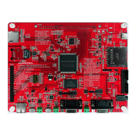
NuMaker-HMI-MA35H0-A1 HARDWARE CONFIGURATION NuMaker-HMI-MA35H04F70 Board 3.1.1 Front View Figure 3-1 shows the main components and connectors from the front side of NuMaker-HMI- MA35H04F70 board. ⚫ Target Chip (U1): MA35H04F764C (LQFP216) MCP package with DDR2 (128 MB). Figure 3-1 Front View of NuMaker-HMI-MA35H04F70 3.1.2 Rear View Figure 3-2 shows the main components and connectors from the rear side of NuMaker-HMI-... -
Page 14: Ddr Phy And Mcp Dram Power Voltage
3.1.4 Audio Codec ⚫ Audio Codec Device (U21): Nuvoton NAU88C22 is audio codec device that integrates microphone input, speaker output and headphone output for audio application on this board. ⚫ Headset Jack (CON8): A headset input jack that follows CTIA definition. -
Page 15: Rmii Megabit Ethernet
NuMaker-HMI-MA35H0-A1 ⚫ Microphone (M1): An on-board microphone for audio sound input. Function GPIO pin of MA35D1 Default Connected R# Conflict Function / R# Name I2S0_MCLK PG11 JTAG_TDO / R372* I2S0_LRCK PG12 JTAG_TCK_SW_CLK / R370* I2S0_BCLK PG13 JTAG_TMS_SW_DIO / R369* I2S0_DI PG14 JTAG_TDI / R368* I2S0_DO... -
Page 16: Qspi Flash
NuMaker-HMI-MA35H0-A1 RMII0_TXD1 RMII0_REFCLK RMII0_CRSDV RMII0_RXD0 RMII0_RXD1 RMII0_RXERR Table 3-5 RMII0 Pin Function Pin of Transformer Pin Name Note (U17) MDI-[1] To RTL8201FI (U16)- MDI+[1] To RTL8201FI (U16)- MDI-[0] To RTL8201FI (U16)- MDI+[0] To RTL8201FI (U16)- To RJ45(CON7) To RJ45(CON7) To RJ45(CON7) To RJ45(CON7) Table 3-6 Transformer (U17) Pin Function 3.1.6... -
Page 17: Nand Flash
NuMaker-HMI-MA35H0-A1 QSPI0_MISO0 QSPI0_MOSI1 QSPI0_MOSI0 QSPI0_CLK QSPI0_MISO1 QSPI0_VDD* Note *: The power group of these GPIO PD0~PD5 belongs to the VDDIO5 power domain of MA35H0 series, the default voltage of VDDIO5 (power input VDD_QSPI0) is VDD1V8 (DC 1.8V) on this NuMaker-HMI- MA35H04F70 board. Table 3-7 QSPI0 Flash (U11) Pin Function 3.1.7 NAND Flash... -
Page 18: Powered By Usb Type C
NUC123 ICE Interface (J16): The ICE interface of NUC123ZD4AN0 microcontroller (U24) for programming the internal Flash of NUC123 series MCU. The internal Flash of NUC123 series MCU had been programmed and acts as an USB VCOM device before the NuMaker-HMI- MA35H04F70 board is delivered by Nuvoton. Pin No. Pin Name Function VCOM_3.3V... -
Page 19: Table 3-12 Booting Source Options
NuMaker-HMI-MA35H0-A1 ⚫ Options for booting source selection: SW7.4 / PG3* SW7.3 / PG2* Booting Source QSPI0 Flash High SD/eMMC* High NAND Flash High High Note * : These GPIO PG2 and PG3 are internal weakly pull-down. : There’s only SD0 micro card slot on this NuMaker-HMI-MA35H04F70 board. Note * Table 3-12 Booting Source Options ⚫... -
Page 20: Table 3-15 Options For Sd Card 0/1 Or Emmc 0/1 Device Booting Source
NuMaker-HMI-MA35H0-A1 Table 3-15 Options for SD Card 0/1 or eMMC 0/1 Device Booting Source SW7.8 / PG7* Boot from SD/eMMC eMMC 4-bit Booting* High Not Supported* Note * : The GPIO PG7 is internal weakly pull-down. : There’s no eMMC memory device on this NuMaker-HMI-MA35H04F70 board. Note * Table 3-16 4/8-bit Options for eMMC NAND Flash Device Booting Source ⚫... -
Page 21: Reset And Rtc Wake-Up Control
NuMaker-HMI-MA35H0-A1 3.1.11 Reset and RTC Wake-up Control ⚫ Reset Button (SW2): Press this key to reset the MA35H04F764C target chip on this NuMaker- HMI-MA35H04F70 board. ⚫ RTC Battery Connector (J10): Optional to supply the RTC power from battery. (DC 3.3V from VDD3V3 on this board by default). - Page 22 NuMaker-HMI-MA35H0-A1 LCM_DATA22 PH14 R520 LCM_DATA21 PH13 R519 LCM_DATA20 PH12 R518 LCM_DATA19 PC15 R517 LCM_DATA18 PC14 R516 LCM_DATA17 PC13 R515 LCM_DATA16 PC12 R514 LCM_DATA15 R513 LCM_DATA14 R512 LCM_DATA13 R511 LCM_DATA12 R510 LCM_DATA11 R509 LCM_DATA10 R508 LCM_DATA9 R507 LCM_DATA8 R506 LCM_DATA7 PI15 R505 LCM_DATA6 PI14...
-
Page 23: Swj
NuMaker-HMI-MA35H0-A1 LCM_XP PB15 R144 LCM_I2C1_SCL / LCM_VSENSE PB11 R146* R145 LCM_XM PB14 R142 LCM_YM PB12 R137 LCM_YP PB13 R139 LCM_I2C5_SCL R143 EBI_ADR13 / PJ13 R188* LCM_I2C5_SDA R141 EBI_ADR12 / PJ12 R186* TOUCH_INT PD12 R136 EBI_nCS1 / R197* LCM_I2C4_SDA PB10 R140 EBI_MCLK / R208* LCM_VSENSE / LCM_I2C4_SCL... -
Page 24: Hs Usb2.0 Connectors
NuMaker-HMI-MA35H0-A1 nRESET signal. ⚫ SWJ Interface (CON12): Arm JTAG and SWD interface for tracing or debugging code. GPIO pin of Default Conflict Function Pin No. Pin Name MA35H0 Connected R# / R# VDD3V3 VDD3V3 JTAG_nTRST PG15 R151 I2S0_DO / R45* JTAG_TDI PG14 R149... -
Page 25: Rs232 Or Rs485
NuMaker-HMI-MA35H0-A1 ⚫ HSUSB1 Host (CON13, USB Type-A Receptacle): HSUSB1 for USB Host with type-A connector. 3.1.15 RS232 or RS485 ⚫ RS232_6: The UART6 to RS232 transceiver (U20,SN75C3232EDR) and Connector (CON24). Pin No. Function Name UR6_TX UR6_RX UR6_CT UR6_RT Table 3-24 RS232_6 Connector (CON24) Pin Funciton ⚫... -
Page 26: Can Fd
NuMaker-HMI-MA35H0-A1 Table 3-26 RS232_16 Connector (CON25) Pin Funciton ⚫ RS485_16: The UART6 to RS485 transceiver (U44, SN65HVD11DR) and Connector (J65). Pin No. Function Name RS485_A2 RS485_B2 Table 3-27 RS485_16 connector (J65) Pin Funciton Note: UART16 can use J68 to switch functions (RS232 or RS485) 3.1.16 CAN FD ⚫... -
Page 27: Sd Card And Microsd Card Slot
NuMaker-HMI-MA35H0-A1 3.1.18 SD Card and MicroSD Card Slot ⚫ SD0 MicroSD Card Slot (CON34): Support SD0 (SD2.0) for optional booting source. Pin No. Pin Name GPIO pin of MA35D1 Default Connected R# SD0_DTA2 R437 SD0_DTA3 R438 SD0_CMD R433- VDD3V3 SD0_CLK R434 SD0_DAT0 R435... -
Page 28: Table 3-32 Sd1 Standard Sd Card Slot (Con32) Pin Function
NuMaker-HMI-MA35H0-A1 SD1_DAT1* R232 SD1_nCD* Note * : The GPIO PN11 pin controls the VDD_SDIO power, the I/O and pull-up voltage of these SD1 group signals, to output 3.3V or 1.8V voltage. Note * : The GPIO PK9 pin or nRESET signal controls the ON/OFF of VDD_SD power that feeds the fixed 3.3V to the Standard SD card slot or not. -
Page 29: Numaker Tft-Lcd7 Board
NuMaker-HMI-MA35H0-A1 NuMaker TFT-LCD7 Board 3.2.1 Front View Figure 3-3 shows the main components from the front view of NuMaker TFT-LCD7 board and an on- board 7’’ 4-wire resistive touch TFT LCD panel. 7-inch Touch LCD Panel Figure 3-3 Front View of NuMaker TFT-LCD7 Board 3.2.2 Rear View Figure 3-4 shows the main components from the rear view of NuMaker TFT-LCD7 board. -
Page 30: Connectors
NuMaker-HMI-MA35H0-A1 Connector (CON1) LCD Module Connector (CN1) Touch Connector (CN5) Figure 3-4 Rear View of NuMaker TFT-LCD7 Board 3.2.3 Connectors ⚫ LCD Module Connector (CN1): FPC (pitch-0.5mm x 50) connector of TFT LCD module. ⚫ LCM Connector (CON1): To connect with the LCM connector (CON14) of the NuMaker-HMI- MA35H04F70 board. -
Page 31: Quick Start
NuMaker-HMI-MA35H0-A1 QUICK START This chapter guides users step by step to start the NuMicro MA35H0 evaluation system based on the NuMaker-HMI-MA35H04F70 board. Configure Power-on Setting Secondly, make sure the power-on setting for the booting source selection on the DIP Switch (SW7) followed the correct ON/OFF states shown in Table 4-1 ~ Table 4-4. -
Page 32: Power On The System
NuMaker-HMI-MA35H0-A1 QSPI0 Flash Low (OFF) High (ON) SD/eMMC High NAND Flash High High Note *: These GPIO PG2 and PG3 are internal weakly pull-down. Table 4-3 SD Boot Source SD/eMMC Configuration ⚫ Options for booting from SD/eMMC device: SW7.7 / PG6* Boot from SD/eMMC Low (OFF) SD0/eMMC0 booting... -
Page 33: Supporting Resources
Arm Cortex-A35 MPUs product line for the MA35H0 series products from the “Products” menu on Nuvoton website homepage. Figure 5-1 Nuvoton Website Software For more details about MA35H0 series software, for example, BSP (Board Support Package), Yocto, website. -
Page 34: Figure 5-2 Ma35H0 Github Resources
NuMaker-HMI-MA35H0-A1 Figure 5-2 MA35H0 GitHub Resources Jan. 29, 2024 Page 34 of 53 Rev 1.02... -
Page 35: Numaker-Hmi-Ma35H0-A1 Schematics
NuMaker-HMI-MA35H0-A1 NUMAKER-HMI-MA35H0-A1 SCHEMATICS NuMaker-HMI-MA35H04F70 Schematic 6.1.1 Power Input Schematic Figure 6-1 shows the power circuit of the NuMaker-HMI-MA35H04F70 board. Figure 6-1 Power Input Schematic Jan. 29, 2024 Page 35 of 53 Rev 1.02... -
Page 36: Adc And Reset Buttons Schematic
NuMaker-HMI-MA35H0-A1 6.1.2 ADC and Reset Buttons Schematic Figure 6-2 shows the Reset buttons circuit of the NuMaker-HMI-MA35H04F70 board. Figure 6-2 ADC and Reset Buttons Schematic Jan. 29, 2024 Page 36 of 53 Rev 1.02... -
Page 37: Power-On Setting And Swj Schematic
NuMaker-HMI-MA35H0-A1 6.1.3 Power-on Setting and SWJ Schematic Figure 6-3 shows the power-on setting and SWJ circuit of the NuMaker-HMI-MA35H04F70 board. Figure 6-3 Power-on Setting and SWJ Schematic Jan. 29, 2024 Page 37 of 53 Rev 1.02... -
Page 38: Key Buttons Schematic
NuMaker-HMI-MA35H0-A1 6.1.4 Key buttons Schematic Figure 6-4 shows the key buttons circuit of the NuMaker-HMI-MA35H04F70 board. Figure 6-4 Key buttons Schematic Jan. 29, 2024 Page 38 of 53 Rev 1.02... -
Page 39: Lcm Schematic
NuMaker-HMI-MA35H0-A1 6.1.5 LCM Schematic Figure 6-5 shows the LCM circuit of the NuMaker-HMI-MA35H04F70 board. Figure 6-5 LCM Schematic Jan. 29, 2024 Page 39 of 53 Rev 1.02... -
Page 40: Qspi0 And Nand Flash Schematic
NuMaker-HMI-MA35H0-A1 6.1.6 QSPI0 and NAND Flash Schematic Figure 6-6 shows the QSPI0 (only SPI NAND Flash device mounted) and NAND flash device circuit of the NuMaker-HMI-MA35H04F70 board. Figure 6-6 QSPI0 and NAND Flash Schematic Jan. 29, 2024 Page 40 of 53 Rev 1.02... -
Page 41: Sd0 Schematic
NuMaker-HMI-MA35H0-A1 6.1.7 SD0 Schematic Figure 6-7 shows the SD0 card slot circuit of the NuMaker-HMI-MA35H04F70 board. Figure 6-7 SD0 Schematic Jan. 29, 2024 Page 41 of 53 Rev 1.02... -
Page 42: Sd1 Schematic
NuMaker-HMI-MA35H0-A1 6.1.8 SD1 Schematic Figure 6-8 shows the SD1 card slot circuit of the NuMaker-HMI-MA35H04F70 board. Figure 6-8 SD1 Schematic Jan. 29, 2024 Page 42 of 53 Rev 1.02... -
Page 43: Rmii0_Pf Schematic
NuMaker-HMI-MA35H0-A1 6.1.9 RMII0_PF Schematic Figure 6-9 shows the RMII0 port circuit of the NuMaker-HMI-MA35H04F70 board. Figure 6-9 RMII0 Schematic Jan. 29, 2024 Page 43 of 53 Rev 1.02... -
Page 44: Gpio Schematic
NuMaker-HMI-MA35H0-A1 6.1.10 GPIO Schematic Figure 6-10 shows the GPIO circuit of the NuMaker-HMI-MA35H04F70 board Figure 6-10 GPIO Schematic Jan. 29, 2024 Page 44 of 53 Rev 1.02... -
Page 45: Nau88C22 Audio Codec Schematic
NuMaker-HMI-MA35H0-A1 6.1.11 NAU88C22 Audio Codec Schematic Figure 6-11 shows the NAU88C22 audio codec circuit of the NuMaker-HMI-MA35H04F70 board. Figure 6-11 NAU88C22 Audio Codec Schematic Jan. 29, 2024 Page 45 of 53 Rev 1.02... -
Page 46: Nuc123 Vcom Schematic
NuMaker-HMI-MA35H0-A1 6.1.12 NUC123 VCOM Schematic Figure 6-12 shows the NUC123 VCOM circuit of the NuMaker-HMI-MA35H04F70 board. Figure 6-12 NUC123 VCOM Schematic Jan. 29, 2024 Page 46 of 53 Rev 1.02... -
Page 47: Hsusb 0/1 Schematic
NuMaker-HMI-MA35H0-A1 6.1.13 HSUSB 0/1 Schematic Figure 6-13 shows the HS (high speed) USB 0/1 circuit of the NuMaker-HMI-MA35H04F70 board. Figure 6-13 HSUSB 0/1 Schematic Jan. 29, 2024 Page 47 of 53 Rev 1.02... -
Page 48: Led, Can Fd, Rs232 And Rs485 Schematic
NuMaker-HMI-MA35H0-A1 6.1.14 LED, CAN FD, RS232 and RS485 Schematic Figure 6-14 shows the LED, CAN FD, RS232 and RS485 circuit of the NuMaker-HMI-MA35H04F70 board. Figure 6-14 LED, CAN FD, RS232 and RS485 Schematic Jan. 29, 2024 Page 48 of 53 Rev 1.02... -
Page 49: Pcb Placement
NuMaker-HMI-MA35H0-A1 6.1.15 PCB Placement Figure 6-15 and Figure 6-16 show the front and rear PCB component placement of the NuMaker-HMI- MA35H04F70 board. Figure 6-15 Front PCB Placement of NuMaker-HMI-MA35H070 Board Jan. 29, 2024 Page 49 of 53 Rev 1.02... -
Page 50: Figure 6-16 Rear Pcb Placement Of Numaker-Hmi-Ma35H070 Board
NuMaker-HMI-MA35H0-A1 Figure 6-16 Rear PCB Placement of NuMaker-HMI-MA35H070 Board Jan. 29, 2024 Page 50 of 53 Rev 1.02... -
Page 51: Numaker Tft-Lcd7 Board Schematic
NuMaker-HMI-MA35H0-A1 NuMaker TFT-LCD7 Board Schematic Figure 6-17 shows the circuit of the NuMaker TFT-LCD7 board. Figure 6-17 NuMaker TFT-LCD7 Board Schematic Jan. 29, 2024 Page 51 of 53 Rev 1.02... -
Page 52: Revision History
NuMaker-HMI-MA35H0-A1 REVISION HISTORY Date Revision Description • 2023.12. 12 1.00 Initial version. • MA35H0 Display Resolution from 1366x768 to 2024.01. 11 1.01 1280x800 • 2024.01. 29 1.02 PN MA35H04F767C to MA35H04F764C Jan. 29, 2024 Page 52 of 53 Rev 1.02... - Page 53 NuMaker-HMI-MA35H0-A1 Important Notice Nuvoton Products are neither intended nor warranted for usage in systems or equipment, any malfunction or failure of which may cause loss of human life, bodily injury or severe property damage. Such applications are deemed, “Insecure Usage”.
Need help?
Do you have a question about the NuMicro Series and is the answer not in the manual?
Questions and answers