Table of Contents
Advertisement
Quick Links
NuMaker-IoT-M467
NuMicro
®
Family
Arm
®
Cortex
®
-M4-based Microcontroller
NuMaker-IoT-M467
User Manual
Evaluation Board for NuMicro
®
M460 Series
The information described in this document is the exclusive intellectual property of
Nuvoton Technology Corporation and shall not be reproduced without permission from Nuvoton.
Nuvoton is providing this document only for reference purposes of NuMicro microcontroller and
microprocessor based system design. Nuvoton assumes no responsibility for errors or omissions.
All data and specifications are subject to change without notice.
For additional information or questions, please contact: Nuvoton Technology Corporation.
www.nuvoton.com
Nov. 10, 2022
Page 1 of 58
Rev 1.00
Advertisement
Table of Contents

Related Manuals for Nuvoton NuMicro NuMaker-IoT-M467


Summary of Contents for Nuvoton NuMicro NuMaker-IoT-M467
- Page 1 The information described in this document is the exclusive intellectual property of Nuvoton Technology Corporation and shall not be reproduced without permission from Nuvoton. Nuvoton is providing this document only for reference purposes of NuMicro microcontroller and microprocessor based system design. Nuvoton assumes no responsibility for errors or omissions.
-
Page 2: Table Of Contents
4.10.2 Status LEDs ........................24 5 QUICK START ....................25 5.1 Toolchains Supporting ....................25 5.2 Nuvoton Nu-Link Driver Installation ................25 5.3 BSP Firmware Download ................... 27 5.4 Hardware Setup ......................27 5.5 Find the Example Project ................... 29 5.6 Execute the Project under Toolchains .............. - Page 3 NuMaker-IoT-M467 6.1 Nu-Link2-Me ......................... 41 6.2 M467 Target Board ...................... 42 6.2.1 Power Source........................42 6.2.2 M467HJHAN ........................43 6.2.3 SPI Flash ......................... 44 6.2.4 Full-speed USB ....................... 45 6.2.5 High-speed USB ......................46 6.2.6 Micro SD Card ........................ 47 6.2.7 Arduino UNO I/F ......................
- Page 4 NuMaker-IoT-M467 List of Figures Figure 1-1 NuMaker-IoT-M467 Evaluation Board ................7 Figure 4-1 Front View of NuMaker-IoT-M467 ................10 Figure 4-2 Rear View of NuMaker-IoT-M467 ................. 11 Figure 4-3 Arduino UNO Compatible Extension Connectors ............12 Figure 4-4 External Power Supply Sources on Nu-Link2-Me ............17 Figure 4-5 External Power Supply Sources on M467 Target Board ..........
- Page 5 NuMaker-IoT-M467 Figure 5-29 Debug Message on Serial Port Terminal Windows ............ 40 Figure 6-1 Nu-Link2-Me Circuit ...................... 41 Figure 6-2 Power Source Circuit ....................42 Figure 6-3 M467HJHAN Circuit...................... 43 Figure 6-4 SPI Flash Circuit ......................44 Figure 6-5 Full-speed USB Circuit ....................45 Figure 6-6 High-speed Circuit ......................
- Page 6 NuMaker-IoT-M467 List of Tables Table 4-1 Extension Connectors ....................12 Table 4-2 Arduino UNO Extension Connectors and M467HJHAN Mapping GPIO List ....13 Table 4-3 mikroBUS™ Mapping with M467HJHAN ............... 14 Table 4-4 Vin Power Source ......................15 Table 4-5 5 V Power Sources ......................15 Table 4-6 3.3 V Power Sources .....................
-
Page 7: Overview
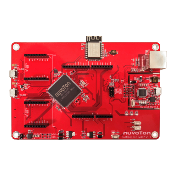
NuMaker-IoT-M467 OVERVIEW The NuMaker-IoT-M467 is an evaluation board for Nuvoton NuMicro M467SJHAN, M467KJHAN, M467JJHAN, M467HJHAN microcontrollers. The NuMaker-IoT-M467 consists of two parts: an M467 target board and an on-board Nu-Link2-Me debugger and programmer. The NuMaker-IoT-M467 is designed for project evaluation, prototype development and validation with power consumption monitoring function. -
Page 8: Features
Online/offline programming – Virtual COM port function – On-board components: 32 Mbits SPI Flash – Thermal sensor (Nuvoton NCT7717U) – User defined LEDs and buttons – 10/100M Ethernet PHY – USB HS OTG and USB FS OTG – Micro SD Card slot –... -
Page 9: Introduction To Numicro Iot Platform
With abstractions API design, the NuMicro IoT platform allows users to focus on application development, not underlying system complexity. For more information on NuMicro IoT platform, please visit NuMicro IoT platform webpage: https://www.nuvoton.com/products/iot-solution/iot-platform/ Nov. 10, 2022 Page 9 of 58... -
Page 10: Hardware Configuration
NuMaker-IoT-M467 HARDWARE CONFIGURATION Front View Arduino UNO Compatible Extension Connectors Wi-Fi Module M467HJHAN RJ-45 Connector mikroBUS Nu-Link2-Me USB FS Connector VCOM Switch ICE USB Connector USB HS Connector ICE Chip: M48SSIDAE ICE Status LED Off-line Program Button User defined LEDs M467 Target Board CAN FD Transceiver Reset Button... -
Page 11: Rear View
Figure 4-2 shows the main components and connectors from the rear side of NuMaker-IoT-M467. The following lists components and connectors from the rear view: Micro SD Card Connector (U5) and SD Card Power LED (SD_PWR) Thermal Sensor (U10, Nuvoton NCT7717U) SPI Flash (U11) Nu-Link2-Me MCUVCC Power Switch (ICEJPR1) –... -
Page 12: Extension Connectors
NuMaker-IoT-M467 Extension Connectors Table 4-1 presents the extension connectors. Connector Description NU1, NU2, NU3, NU4 Arduino UNO compatible pins on the NuMaker-IoT-M467. and NU5 Table 4-1 Extension Connectors 4.3.1 Arduino UNO Compatible Extension Connectors Figure 4-3 shows the Arduino UNO compatible extension connectors. MISO RESET PA.9... -
Page 13: Table 4-2 Arduino Uno Extension Connectors And M467Hjhan Mapping Gpio List
NuMaker-IoT-M467 NuMaker-IoT-M467 NuMaker-IoT-M467 Header Header Compatible to Compatible to GPIO Pin of M467 GPIO Pin of M467 Arduino UNO Arduino UNO NU4.1 PB.2 NU3.6 PB.6 NU4.2 PB.3 NU3.5 PB.7 NU4.3 PC.9 NU3.4 PB.8 NU4.4 PC.10 NU3.3 PB.9 NU4.5 PC.11 NU3.2 PB.0 NU4.6 PC.12... -
Page 14: Mikrobus Tm Interface
NuMaker-IoT-M467 mikroBUS Interface NuMaker-IoT-M467 features a MikroElektronika mikroBUS™ socket which has the smallest number of pins but has maximum expandability. The MikroElektronika mikroBUS™ consists of communications pins including SPI, UART and I C, one PWM pin, one interrupt pin, one analog input pin, one reset pin and one chip select pin, and has 3.3V and 5V power pin. -
Page 15: Power Supply Configuration
NuMaker-IoT-M467 Power Supply Configuration The NuMaker-IoT-M467 is able to adopt multiple power supplies. External power sources include NU1 Vin (7 V to 12 V), V (depending on the target chip operating voltage), and PC through USB connector. By using switches and voltage regulator, multiple power domains can be created on the NuMaker-IoT- M467. -
Page 16: Power Sources
NuMaker-IoT-M467 4.5.3 3.3 V Power Sources Table 4-6 presents the 3.3 V power sources. Voltage 5 V Source Description Regulator ICEUP1 converts USB_HS_VBUS to 3.3 V and ICEUP1 USB_HS_VBUS supplies 3.3 V to M467 target board or ICE chip. UP2 converts FSUSB_VBUS to 3.3 V and supplies 3.3 FSUSB_VBUS V to M467 target board. -
Page 17: Usb Connectors
NuMaker-IoT-M467 4.5.5 USB Connectors Table 4-8 presents the USB connectors. Connector Description ICE USB connector on Nu-Link2-Me for power supply, debugging and ICEJ3 programming from PC. USB FS connector on NuMaker-M467HJ for power supply. USB HS connector on NuMaker-M467HJ for power supply. Table 4-8 USB Connectors 4.5.6 Power Switches... -
Page 18: Figure 4-5 External Power Supply Sources On M467 Target Board
NuMaker-IoT-M467 To use ICEJ3 as external power supply source with Nu-Link2-Me, please follow the steps below: Solder the resistor on ICEJPR1 (MCUVCC) depending on the target chip operating voltage. Solder the resistor on ICEJPR2 (ICEVCC) depending on the ICE chip operating voltage. Connect the external power supply to ICEJ3. -
Page 19: Figure 4-6 Detach The Nu-Link2-Me From Numaker-Iot-M467
NuMaker-IoT-M467 To use JP1 as external power supply source, please follow the steps below: Remove the resistor on ICEJPR1 (MCUVCC). Solder the resistor on ICEJPR2 (ICEVCC) depending on the ICE chip operating voltage. Connect ICEJ3 to PC. Connect the external power supply to JP1. To use Vin or J2 or J3 as external power supply source with Nu-Link2-Me detached from NuMaker-IoT-M467, please follow the steps below: Detach the Nu-Link2-Me from NuMaker-IoT-M467. -
Page 20: Table 4-11 Supply External Power For M467 Target Board
NuMaker-IoT-M467 Table 4-11 presents all power models when supplies external power through M467 target board. The M467 target board external power sources are highlighted in yellow. ICEJPR1 ICEJPR2 Target Chip ICE Chip Model ICEJ3 (MCUVCC) (ICEVCC) Voltage Voltage Selection Selection 7 V ~ 12 V Remove 3.3 V... -
Page 21: External Reference Voltage Connector
NuMaker-IoT-M467 External Reference Voltage Connector Table 4-13 presents the external reference voltage connector. Connector Description Connector for user to connect to the external reference voltage pin of the VREF target chip. User needs to remove the L2 ferrite bead. Table 4-12 External Reference Voltage Connector Ammeter Connector Table 4-13 presents the ammeter connector. -
Page 22: Push Buttons
NuMaker-IoT-M467 Push Buttons Table 4-14 presents the push buttons. Component Description ICESW1 Offline program button to start offline ICP programming the target chip. Reset button to reset the target chip. Table 4-14 Push Buttons Nov. 10, 2022 Page 22 of 58 Rev 1.00... -
Page 23: Leds
NuMaker-IoT-M467 LEDs Table 4-15 presents the LEDs. Component Description Power LED The power LED indicates that the NuMaker-IoT-M467 is powered. Red LED The red LED is connected to the target chip PH.4. Yellow LED The yellow LED is connected to the target chip PH.5. Green LED The green LED is connected to the target chip PH.6. -
Page 24: Status Leds
NuMaker-IoT-M467 4.10.2 Status LEDs Table 4-15 presents the status LEDs patterns for different operation on Nu-Link2-Me. Status LED Operation Status ICES0 ICES1 ICES2 ICES3 Boot Flash x 3 Flash x 3 Flash x 3 Flash x 3 Idle One Nu-Link2-Me is selected to connect Flash x 3 Flash x 3 Flash x 3... -
Page 25: Quick Start
KEIL MDK Nuvoton edition IAR EWARM NuEclipse GCC (for Windows) NuEclipse GCC (for Linux) Nuvoton Nu-Link Driver Installation Download and install the latest Nuvoton Nu-Link Driver. Download and install Nu-Link_Keil_Driver when using Keil MDK. Download and install Nu-Link_IAR_Driver when using IAR EWARM. -
Page 26: Figure 5-2 Nu-Link Usb Driver Installation
NuMaker-IoT-M467 Figure 5-2 Nu-Link USB Driver Installation Nov. 10, 2022 Page 26 of 58 Rev 1.00... -
Page 27: Bsp Firmware Download
NuMaker-IoT-M467 BSP Firmware Download Download and unzip the Board Support Package (BSP). Hardware Setup Open the virtual COM (VCOM) function by changing Nu-Link2-Me VCOM Switch No. 1 and 2 to ON. Figure 5-3 Open VCOM Function Connect the ICE USB connector shown in Figure 5-4 to the PC USB port through a USB cable. -
Page 28: Figure 5-5 Device Manger
NuMaker-IoT-M467 Find the “Nuvoton Virtual COM Port” on the Device Manger as Figure 5-5. Figure 5-5 Device Manger Open a serial port terminal, PuTTY for example, to print out debug message. Set the speed to 115200. Figure 5-6 presents the PuTTY session setting. -
Page 29: Find The Example Project
NuMaker-IoT-M467 Find the Example Project Use the “Template” project as an example. The project can be found under the BSP folder as shown in Figure 5-7. M460_Series_BSP_CMSIS_V3.XX.XXX SampleCode Template Keil Figure 5-7 Template Project Folder Path Execute the Project under Toolchains Open and execute the project under the toolchain. -
Page 30: Figure 5-9 Project File Migrate To Version 5 Format
Make sure the debugger is “Nuvoton Nu-Link Debugger” as shown in Figure 5-10 and Figure 5-11. Figure 5-10 Debugger Setting in Options Window Note: If the dropdown menu in Figure 5-10 does not contain “Nuvoton Nu-Link Debugger” item, please rework section 5.2. Nov. 10, 2022 Page 30 of 58 Rev 1.00... -
Page 31: Figure 5-11 Programming Setting In Options Window
NuMaker-IoT-M467 Figure 5-11 Programming Setting in Options Window Rebuild all target files. After successfully compiling the project, download code to the Flash memory. Click “Start/Stop Debug Section” button to enter debug mode. 1. Rebuild 2. Successfully compile 3. Download 4. Start/Stop Debug Figure 5-12 Compile and Download the Project Nov. -
Page 32: Figure 5-13 Keil Mdk Debug Mode
NuMaker-IoT-M467 Figure 5-13 shows the debug mode under Keil MDK. Click “Run” and the debug message will be printed out as shown in Figure 5-14. User can debug the project under debug mode by checking source code, assembly language, peripherals’ registers, and setting breakpoint, step run, value monitor, etc. -
Page 33: Iar Ewarm
NuMaker-IoT-M467 5.6.2 IAR EWARM This section provides steps to beginners on how to run a project by using IAR EWARM. Double click the “Template.eww” to open the project. Make sure the toolbar contains “Nu-Link” item as shown in Figure 5-15. Note: If the toolbar does not contain “Nu-Link”... -
Page 34: Figure 5-17 Iar Ewarm Debug Mode
NuMaker-IoT-M467 Figure 5-17 shows the debug mode under IAR EWARN. Click “Go” and the debug message will be printed out as shown in Figure 5-18. User can debug the project under debug mode by checking source code, assembly language, peripherals’ registers, and setting breakpoint, step run, value monitor, etc. -
Page 35: Nueclipse
NuMaker-IoT-M467 5.6.3 NuEclipse This section provides steps to beginners on how to run a project by using NuEclipse. Please make sure the filenames and project folder path contain neither invalid character nor space. Double-click “NuEclipse.exe" to open the toolchain. Import the “Template” project by following the steps presented in Figure 5-19 and Figure 5-20. Figure 5-19 Import the Project in NuEclipse M460_Series_BSP_CMSIS_V3.XX.XXX\SampleCode\Template M460_Series_BSP_CMSIS_V3.XX.XXX\SampleCode\Template\GCC) -
Page 36: Figure 5-21 Open Project Properties Window
NuMaker-IoT-M467 Click the “Template” project and find the project properties as shown in Figure 5-21. Make sure the settings are the same as settings in Figure 5-22. Figure 5-21 Open Project Properties Window Figure 5-22 Project Properties Settings Nov. 10, 2022 Page 36 of 58 Rev 1.00... -
Page 37: Figure 5-23 Build Project
NuMaker-IoT-M467 Click the “Template” project and build the project. Figure 5-23 Build Project After the project is built, click the “Template” project and set the “Debug Configuration” as shown in Figure 5-24. Follow the settings presented in Figure 5-25, Figure 5-26 and Figure 5-27 to enter debug mode. -
Page 38: Figure 5-25 Main Tab Configuration
NuMaker-IoT-M467 Note 1: Double-click the “GDB Nuvoton Nu-Link Debugging” to create the sub item. Note 2: After the project is built, the “*.elf” file will be shown in “C/C++ Application” frame. Figure 5-25 Main Tab Configuration Figure 5-26 Debugger Tab Configuration Nov. -
Page 39: Figure 5-27 Startup Tab Configuration
NuMaker-IoT-M467 Note: User must follow those settings highlighted in green, and configure other settings depending on the needs. Figure 5-27 Startup Tab Configuration Nov. 10, 2022 Page 39 of 58 Rev 1.00... -
Page 40: Figure 5-28 Nueclipse Debug Mode
NuMaker-IoT-M467 Figure 5-28 shows the debug mode under NuEclipse. Click “Resume” and the debug message will be printed out as shown in Figure 5-29. User can debug the project under debug mode by checking source code, assembly language, peripherals’ registers, and setting breakpoint, step run, value monitor, etc. -
Page 41: Numaker-Iot-M467 Schematics
NuMaker-IoT-M467 NUMAKER-IOT-M467 SCHEMATICS Nu-Link2-Me Figure 6-1 shows the Nu-Link2-Me circuit. 3.3V ICER1 O f f - page C onnect or 200 1% USB_HS_CAP R0603 ICEC1 ICEC2 0.1u C0603 C0603 SWDH_DAT TICEDAT SWDH_CLK TICECLK SWDH_RST# TICERST ICE_RX_S COM_TX ICE_TX_S COM_RX ICE_RST nRESET ICEVDD VDDIO... -
Page 42: M467 Target Board
NuMaker-IoT-M467 M467 Target Board 6.2.1 Power Source Figure 6-2 shows the power source circuit. AMS1117_5v UNO_VIN LDO_5V UNO_5V SS24A RB060L 10uF/10V TANT-A VDD_MCU HEADER1X4(NC) header1x4 R0603 Power Source LDO_3_3V R0603 HEADER1X4(NC) AMMETER ICE5V FERRITE BEAD header1x4 L0603 HEADER2X1 MCUVCC_DIODE UNO_5V AMS1117_3.3v Power Source FSUSB_VBUS... -
Page 43: M467Hjhan
NuMaker-IoT-M467 6.2.2 M467HJHAN Figure 6-3 shows the M467HJHAN circuit. VDD_MCU HEADER5X2(NC) HEADER5X2 R0603 R0603 ICE_DAT ICE_CLK 0.1u VDD_MCU COM_TX nRESET C0603 COM_RX RESET R0603 ICE SWD & Debug Port 3x6x5 2PIN SMD nRESET SW-2P-SMD C0603 PIN1 EPWM_CH0 PIN89 UNO_D7 RESET PIN2 EPWM_CH1 PIN90... -
Page 44: Spi Flash
NuMaker-IoT-M467 6.2.3 SPI Flash Figure 6-4 shows the SPI Flash circuit. PIN66 PI12 SPIM_SS QSPI0_MISO1 FLASH_nCS PIN67 PI13 SPIM_MISO QSPI0_MOSI1 FLASH_MISO PIN68 PI14 SPIM_D2 QSPI0_SS FLASH_IO2 PIN69 PI15 SPIM_D3 QSPI0_CLK FLASH_IO3 PIN70 SPIM_CLK QSPI0_MISO0 FLASH_CLK PIN71 SPIM_MOSI QSPI0_MOSI0 FLASH_MOSI off-Page Singals SPIM / QSPI Selection... -
Page 45: Full-Speed Usb
NuMaker-IoT-M467 6.2.4 Full-speed USB Figure 6-5 shows the full-speed USB circuit. PIN163 PC14 FSUSB_VBUS_ST PIN164 PB15 FSUSB_VBUS FSUSB_VBUS_EN PIN123 PA12 PIN124 PA13 FSUSB_D- PIN125 PA14 FSUSB_D+ PIN126 PA15 FSUSB_ID off-Page Singals 4.7K R0603 LDO_5V FSUSB_VBUS FSUSB_VBUS_ST FSUSB_VBUS VBUS FSUSB_VBUS_EN Shield EN/EN# R0603 Shield... -
Page 46: High-Speed Usb
NuMaker-IoT-M467 6.2.5 High-speed USB Figure 6-6 shows the high-speed USB circuit. PIN154 PJ12 HSUSB_VBUS_ST PIN155 PJ13 HSUSB_VBUS_EN HSUSB_VDD33 HSUSB_VDD33 PIN133 HSUSB_VDD12_CAP HSUSB_VDD12_CAP PIN127 HSUSB_VRES HSUSB_VRES HSUSB_VBUS PIN128 PIN131 HSUSB_VSS PIN129 200R 1% PIN130 0.1u R0603 HSUSB_D- PIN132 C0603 C0603 FERRITE BEAD HSUSB_D+ PIN134 L0603... -
Page 47: Micro Sd Card
NuMaker-IoT-M467 6.2.6 Micro SD Card Figure 6-7 shows the micro SD card circuit. PIN122 PD13 SD0_nCS SDHC_nCS PIN135 SD0_CMD SDHC_CMD PIN136 SD0_CLK SDHC_CLK PIN137 SD0_DAT3 SDHC_DAT3 PIN138 SD0_DAT2 SDHC_DAT2 PIN139 SD0_DAT1 SDHC_DAT1 PIN140 SD0_DAT0 SDHC_DAT0 off-Page Singals SD_PWR 0805 LED G (綠光) 普亮 8P4R-10K LED0805 8P4RA... -
Page 48: Arduino Uno I/F
NuMaker-IoT-M467 6.2.7 Arduino UNO I/F Figure 6-8 shows the Arduino UNO interface circuit. PIN176 EADC0_CH6 UNO_A0 PIN175 EADC0_CH7 UNO_A1 VREF PIN174 EADC0_CH8 UNO_SCL UNO_A2 I2C_SCL UNO_VIN UNO_3VCC VDD PIN173 EADC0_CH9 UNO_SDA UNO_A3 I2C_SDA PIN10 EADC0_CH0 UNO_A4 VREF PIN9 EADC0_CH1 UNO_5V UNO_A5 UNO_D13 PIN4... -
Page 49: Can Fd Transceiver
NuMaker-IoT-M467 6.2.8 CAN FD Transceiver Figure 6-9 shows the CAN FD transceiver circuit. PIN152 PJ10 CAN0_TX CAN-FD_TX PIN153 PJ11 CAN0_RX CAN-FD_RX off-Page Singals CAN0_TX R0603 CAN0_H CANH CAN0_L CANL CAN0_RX R0603 FAULT TCAN337GD HEADER2X1(2.54mm, male, top) 0.1u 4.7K 0.1u C0603 C0603 R0603 C0603... -
Page 50: Ethernet Phy
NuMaker-IoT-M467 6.2.9 Ethernet PHY Figure 6-10 shows the Ethernet PHY circuit. 4.7K VDD3V3 0.1u FERRITE BEAD R0603 PHY _AVDD3V3 C0603 L0603 0.1u R0603 0.1u C0603 0.01u PHY _VDD3V3 C0603 C0603 R0603 0.01u 0.1u C0603 1000p/2KV C0603 C0603 C1206 LED0 4.7K PHY _VDD3V3 R0603 4.7K... -
Page 51: Thermal Sensor
NuMaker-IoT-M467 6.2.10 Thermal Sensor Figure 6-11 shows the thermal sensor circuit. PIN121 I2C2_SDA I2C2_SDA PIN120 I2C2_SCL I2C2_SCL The 6-axis motion sensor (MPU6500) and thermal sensor (NCT7717U) are shared with same I2C bus (I2C2) off-Page Singals 4.7K 4.7K R0603 R0603 I2C2_SCL I2C2_SDA 0.1u ALERT#... -
Page 52: Leds & Buttons
NuMaker-IoT-M467 6.2.11 LEDs & Buttons Figure 6-12 shows the LEDs and buttons circuit. PIN47 LED_R PIN48 LED_Y PIN49 LED_G PIN43 BTN_0 PIN44 BTN_1 off-Page Singals LEDG LED_G 0805 LED G (綠光) 普亮 R0603 LED0805 LEDY LED_Y BTN0 R0603 BTN1 R0603 3x6x5 2PIN SMD 3x6x5 2PIN SMD BTN_0... -
Page 53: Wi-Fi Module
NuMaker-IoT-M467 6.2.12 Wi-Fi Module Figure 6-13 shows the Wi-Fi module circuit. PIN90 WFIF_RST PIN91 UART2_nRTS WIFI_nCTS PIN92 UART2_nCTS WIFI_nRTS PIN93 UART2_TXD WIFI_TXD PIN94 UART2_RXD WIFI_RXD off-Page Singals ESP-12 10KR R0603 10KR WFIF_RST WIFI_RXD R0603 WIFI_TXD 10KR R0603 IO16 WiFi_IO0 IO14 IO12 WIFI_nCTS WIFI_nRTS... -
Page 54: Mikrobus Tm Interface
NuMaker-IoT-M467 6.2.13 mikroBUS Interface Figure 6-14 shows the mikroBUS interface circuit. PIN19 PD11 EADC1_CH1 MBUS0_AN PIN148 PH11 EPWM0_CH5 MBUS0_PWM PIN99 PG11 MBUS0_RST PIN100 PG12 MBUS0_INT PIN25 I2C1_SCL MBUS0_SCL PIN26 I2C1_SDA MBUS0_SDA PIN29 SPI1_MISO MBUS0_MISO PIN30 SPI1_MOSI MBUS0 MBUS0_MOSI PIN31 SPI1_CLK MBUS0_AN MBUS0_PWM MBUS0_CLK... -
Page 55: 6-Axis Sensor
NuMaker-IoT-M467 6.2.14 6-Axis Sensor Figure 6-15 shows the 6-Axis sensor circuit. PIN121 I2C2_SDA I2C2_SDA PIN120 I2C2_SCL I2C2_SCL PIN119 M_SENSOR_INT The 6-axis motion sensor (MPU6500) and thermal sensor (NCT7717U) are shared with same I2C bus (I2C2) off-Page Singals I2C2_SCL I2C2_SDA MPU6500 0.1uF 10nF 0.1uF... -
Page 56: Pcb Placement
NuMaker-IoT-M467 PCB Placement Figure 6-16 and Figure 6-17 show the front and rear placement of NuMaker-IoT-M467. Figure 6-16 Front Placement Figure 6-17 Rear Placement Nov. 10, 2022 Page 56 of 58 Rev 1.00... -
Page 57: Revision History
NuMaker-IoT-M467 REVISION HISTORY Date Revision Description 2022.11.10 1.00 Initial version. Nov. 10, 2022 Page 57 of 58 Rev 1.00... - Page 58 NuMaker-IoT-M467 Important Notice Nuvoton Products are neither intended nor warranted for usage in systems or equipment, any malfunction or failure of which may cause loss of human life, bodily injury or severe property damage. Such applications are deemed, “Insecure Usage”.
Need help?
Do you have a question about the NuMicro NuMaker-IoT-M467 and is the answer not in the manual?
Questions and answers