Table of Contents
Advertisement
Quick Links
ISL94212EVKIT1Z
Evaluation Kit User Guide
Description
The ISL94212EVKIT1Z is a kit that facilitates use of the
ISL94212
BMS device. The ISL94212 monitors cell voltage and
temperature. It converts the cell voltages and temperatures to
14-bit digital values, provides cell balance control, It provides
significant fault detection. The ISL94212 can operate in a single
device configuration, or multiple kits can be cascaded using a
built-in daisy chain connection. The daisy chain hardware
provides robust, redundant board-to- board communications.
Specifications
This board has been configured and optimized for the following
operating conditions:
• V
= 6V to 60V
BAT
• V
daisy chain = 10V to 60V
BAT
• VC
(for n = 1 to 12) = V(VCn-1) to V(VCn-1) + 5V
n
• CB
(for n = 1 to 9) = V(VCn-1) to V(VCn-1) + 9V
n
• CB
(for n = 10 to 12) = V(VCn) -9V to V(VCn)
n
• External inputs Ext
= 0V to 2.5V
1 -4
• SPI communications refer to
• V
(V
) voltage (rising) typical 5.1V
POR
BAT
ANALOG FRONT END
LEVEL SHIFTING
VOLTAGE MONITOR
TEMP MONITOR
OV, OT DETECTION
OPEN WIRE DETECT
CELL BALANCING
VOLTAGE REGULATOR
ADC
Applications requiring 12 cells or less can operate with a single device as
shown above.
Also the ISL94212 can also operate in a 2 to 14 device configuration (Daisy
Chain). See example to the right.
FIGURE 1. SINGLE DEVICE CONFIGURATION
UG048 Rev 0.00
August 26, 2015
ISL94212
datasheet
MICROCONTROLLER
CURRENT MONITORING
SPI
COMMUNICATION
POWER FET CONTROL
PACK CAPACITY MONITOR
FET DRIVER
CURRENT
Key Features
• Supports both stand alone and daisy chained configurations
• Daisy chaining with both connector only or wire jumper
options
• GUI provided export option for generation of detailed
register and/or SPI communications log files.
• USB dongle runs HID firmware for driver-less enumeration
and communications with Windows platforms
• GUI add-in chart generation tool supports real-time
graphing, zoom and export of captured data.
• Software provides checksum requirements associated with
daisy chain communications.
• Kit includes "Battery Emulation" board(s) for cell voltages
generation.
References
ISL94212
web page
ISL94212
datasheet
Ordering Information
PART NUMBER
ISL94212EVKIT1Z
ISL94212EVZ
NOTE: See "What is inside" on
SYSTEM
ELECTRONICS
USER'S MANUAL
August 26, 2015
DESCRIPTION (Note)
ISL94212 master
ISL94212 slave/daisy chain kit to be
used as either "middle" or "top" device(s)
page 2
for kit details.
MICRO-
CONTROLLER
FIGURE 2. DAISY CHAIN CONFIGURATION
Page 1 of 24
UG048
Rev 0.00
Advertisement
Table of Contents

Related Manuals for Renesas ISL94212EVKIT1Z


Summary of Contents for Renesas ISL94212EVKIT1Z
- Page 1 Rev 0.00 August 26, 2015 Description Key Features The ISL94212EVKIT1Z is a kit that facilitates use of the • Supports both stand alone and daisy chained configurations ISL94212 BMS device. The ISL94212 monitors cell voltage and • Daisy chaining with both connector only or wire jumper temperature.
-
Page 2: Document Overview
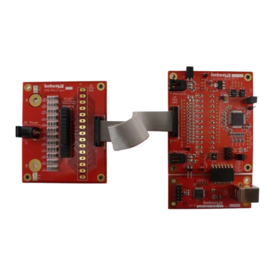
ISL94212EVKIT1Z Document Overview What is inside The following are three key portions of this document: The ISL94212EVKIT1Z (Master) evaluation kit contains: • ISL94212EV1Z evaluation board Software Installation • MCB_PS2_Z multicell power supply test board The software is necessary to use this evaluation kit. This section guides you through the installation and verification of both the •... -
Page 3: Pcb Layout Guidelines
ISL94212EVKIT1Z As mentioned in the “Quick Hardware Setup Guide” on page while each board is operation in 60V range, total voltage across multiple packs can be dangerous. PCB Layout Guidelines The ISL94212 layout has been optimized for electrical and protection during hot plug conditions. - Page 4 CMSSel2 = 0 ISL94212 Enable CMRSel0 = 1 6V to 60V CMRSel1 = 1 (Not used in single board application) CMRSel MCB_PS2_Z BOARD MCB_MICRO_EVZ FIGURE 3. ISL94212EVKIT1Z SINGLE BOARD SETUP UG048 Rev 0.00 Page 4 of 24 August 26, 2015...
-
Page 5: Daisy Chain
ISL94212EVKIT1Z FIGURE 4. ISL94212EVZ Step 10: Open the ISL94212 GUI software, select the “BMS a battery installation, where the ground of one board is Evaluation Board Connected” in the “Select Option” box the VBAT of another, but it easily facilitates testing of as seen in step one. - Page 6 ISL94212EVKIT1Z Step 7: Check the jumpers and switches on the board. Since Step 9: Turn on the power to the supply and notice that there is this is a daisy chain configuration, the boards should be a green LED (VDD) on each board, indicating the LDO configured as follows: regulators on the ISL94212 are operating.
- Page 7 CONNECTION 6V to 60V DAISY NORMAL DAISY CHAIN CONNECTION 6V to 60V TO PC FIGURE 5. ISL94212EVZ IN 36-CELL DAISY CHAIN CONFIGURATION (SHOWN 1 ISL94212EVKIT1Z (MASTER) AND 2 ISL94212EV1Z (SLAVES) UG048 Rev 0.00 Page 7 of 24 August 26, 2015...
- Page 8 ISL94212EVKIT1Z Quick GUI Setup Guide (Using the Step 5: The “Device Commands” buttons along the bottom of the main tab are commands sent to all boards in the GUI) system. So, selecting “Scan Volts” then “Read Volts” causes all boards to read the cell voltages,...
-
Page 9: Chart Window
ISL94212EVKIT1Z Chart Window At the end of a sample period, the captured data can be exported to a file that can be loaded into Excel for further analysis by The charting function of the GUI provides real time viewing of the clicking on the “Export”... -
Page 10: Monitor Tab
ISL94212EVKIT1Z Monitor Tab At this time, it is not possible to select the results for any other boards in the stack. Individual boards can be monitored in the The monitor tab shows the voltages and status of the first 4 main window, one board at a time. -
Page 11: Fault Tab
ISL94212EVKIT1Z Fault Tab To clear a bit, click on the bit that is set (or write a 0 in the box at the right to reset all bits.) Then, click on the “Write” button at the The fault tab shows the status of the fault register of the selected end of each fault register, or click on the “Write Group”... -
Page 12: Command Tab
ISL94212EVKIT1Z Command Tab command. This command can then be sent to the chosen device. The image in Figure 10 shows the command for SLEEP. The command tab allows individual commands to be sent to any device in the stack (or all devices, if device 15 is chosen.) This tab NOTE: This screen shows a selection for ISL78600 and includes a raw message sender and CRC4 calculator. - Page 13 ISL94212EVKIT1Z ISL94212 Evaluation Board FIGURE 11. TOP SIDE FIGURE 12. BOTTOM SIDE UG048 Rev 0.00 Page 13 of 24 August 26, 2015...
- Page 14 Schematic SCK600 CS600 DHI10 DLO10 SW DPDT SLIDE DGND DGND DGND 600 Fail Place vias on board at these locations CB10 DREADY 100n FAULT DGND 100n ComRate0 ComRate1 100n ISL94212 ComSel1 ComSel2 100n Base 100n 100n V2P5 100n VREF 100n ISL94212ANZ 100n VRef...
- Page 15 Schematic (Continued) 330k C112 100/1W NDS0605 YELLOW YELLOW NDS7002A C106 100/1W 330k 330k C111 100/1W NDS0605 YELLOW YELLOW NDS7002A C105 100/1W 330k 330k C110 NDS0605 100/1W YELLOW YELLOW NDS7002A C104 100/1W 330k 100/1W 100/1W YELLOW YELLOW NDS7002A NDS7002A C109 C103 330k 330k 100/1W...
- Page 16 Schematic (Continued) 94212 Daisy Chain Place vias on board at these locations UPHI DHI20 220pF/1000V DLO2 UPHI DLO2 82pF 82pF DHI2 82pF 82pF DHI2 UPLO Dai syUp DLO20 220pF/1000V UPLO Place vias on board at these locations DWNHI DHI10 220pF/1000V DLO1 DWNHI DLO1...
-
Page 17: Bill Of Materials
Bill of Materials REFERENCE DESIGNATOR DESCRIPTION MANUFACTURER CAP, SMD, 1812, 0.18µF, 100V, 10%, X7R, ROHS MURATA C14, C15, C54, C56 CAP, SMD, 0805, 220pF, 1kV, 5%, C0G, ROHS VISHAY/VITRAMON C17-C20, C40a, C42a, C101-C112 CAP, SMD, 0603, 0.01µF, 16V, 1 0%, X7R, ROHS VENKEL C2-C13, C16 CAP, SMD, 0603, 0.1µF, 16V, 10%, X7R, ROHS... - Page 18 Bill of Materials (Continued) REFERENCE DESIGNATOR DESCRIPTION MANUFACTURER R23-R26 RES, SMD, 0603, 40.2k, 1/10W, 1%, TF, ROHS YAGEO R27-R30 THERMISTOR-NTC, SMD, 0603, 10k, 1%, - 40 +125°C, ROHS MURATA R3, R19, R96, R97 RES, SMD, 0603, 470Ω,1/10W, 1%, TF, ROHS ROHM RES, SMD, 1206, 100Ω, 1/4W, 1%, TF, ROHS STACKPOLE...
- Page 19 ISL94212EVKIT1Z Layout FIGURE 16. TOP LAYER FIGURE 17. MIDDLE LAYER 1 FIGURE 18. MIDDLE LAYER 2 FIGURE 19. BOTTOM LAYER UG048 Rev 0.00 Page 19 of 24 August 26, 2015...
- Page 20 ISL94212EVKIT1Z Layout (Continued) FIGURE 20. SILK TOP LAYER FIGURE 21. SILK BOTTOM LAYER UG048 Rev 0.00 Page 20 of 24 August 26, 2015...
-
Page 21: Default Configuration Settings
This identifies the point of communication failure. It could be a • The primary ISL94212EVKIT1Z kit is set for non-daisy chain bad daisy chain cable or some problem with that operation. -
Page 22: Typical Performance Curves
ISL94212EVKIT1Z Typical Performance Curves Unless noted: V 24V or 48V as designated = +25°C. Curves provided below are Batt based on exported data from the ISL94212 GUI software. Measurements are captured from three ISL94212 devices operating in daisy chain mode. -
Page 23: Voltage Inputs
ISL94212EVKIT1Z Voltage Inputs 47.970 24.010 24.000 47.965 23.990 47.960 23.980 47.955 23.970 47.950 23.960 47.945 23.950 47.940 23.940 47.935 23.930 TIME (MINUTES) TIME (MINUTES) FIGURE 26. V DEVICE TO DEVICE 24V FIGURE 27. V DEVICE TO DEVICE 48V VCell1-1 VCell1-1 2.004... - Page 24 10. It is the responsibility of the buyer or distributor of Renesas Electronics products, or any other party who distributes, disposes of, or otherwise sells or transfers the product to a third party, to notify such third party in advance of the contents and conditions set forth in this document.
- Page 25 Power Management IC Development Tools Click to view products by manufacturer: Renesas Other Similar products are found below : EVAL-ADM1168LQEBZ EVB-EP5348UI MIC23451-AAAYFL EV MIC5281YMME EV DA9063-EVAL ADP122-3.3-EVALZ ADP130- 0.8-EVALZ ADP130-1.2-EVALZ ADP130-1.5-EVALZ ADP130-1.8-EVALZ ADP1714-3.3-EVALZ ADP1716-2.5-EVALZ ADP1740-1.5- EVALZ ADP1752-1.5-EVALZ ADP1828LC-EVALZ ADP1870-0.3-EVALZ ADP1871-0.6-EVALZ ADP1873-0.6-EVALZ ADP1874-0.3- EVALZ ADP1882-1.0-EVALZ ADP199CB-EVALZ ADP2102-1.25-EVALZ ADP2102-1.875EVALZ ADP2102-1.8-EVALZ ADP2102-2-...
Need help?
Do you have a question about the ISL94212EVKIT1Z and is the answer not in the manual?
Questions and answers