Advertisement
ISL97671/2/3/4IRZ-EVAL
ISL97671/2/3/4IRZ-EVAL Quick Start Guide
This quick start guide pertains to the
ISL97671/2/3/4IRZ-EVAL Evaluation Board. This board
comes populated with 72 LEDs in a 6P12S
configuration to simplify evaluation and testing. Please
install the Sunlight ISL97670 GUI from Intersil's
website, which will be used to control ISL97671/3/4
2
parts via I
C. Note the slave address on the ISL97671,
Isl97673 and ISL97674 is hexadecimal 58; see Figure
1. Please refer to "ISL97671" on page 1, "ISL97672"
on page 2, "ISL97673" on page 2 and "ISL97674" on
page 3, for jumper settings and power-up instructions.
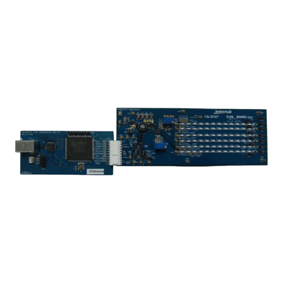
2
FIGURE 2. I
AN1581 Rev 0.00
August 3, 2010
FIGURE 1. EXAMPLE OF GUI INTERFACE
C INTERFACE BOARD CONNECTED TO ISL97671IRZ-EVAL EVALUATION BOARD
USER'S MANUAL
ISL97671
1. Jumpers JP7B, JP8B, JP9, JP10, JP11, JP12 and
JP13 should be inserted for LED's in 6P12S
configuration.
2. Jumpers in line 1, plus JP14, JP15, JP16, JP17,
JP18 and JP19 should be inserted for LED's in
6P10S configuration.
3. Jumper JP5A, JP3A and JP6A are inserted.
2
4. Connect the I
C interface board to the
ISL97671/2/3/4IRZ-EVAL Evaluation Board as
shown in Figure 2 for I
AN1581
Rev 0.00
August 3, 2010
2
C control.
Page 1 of 7
Advertisement
Table of Contents

Related Manuals for Renesas ISL97671IRZ-EVAL


Summary of Contents for Renesas ISL97671IRZ-EVAL
- Page 1 3, for jumper settings and power-up instructions. ISL97671/2/3/4IRZ-EVAL Evaluation Board as shown in Figure 2 for I C control. FIGURE 1. EXAMPLE OF GUI INTERFACE FIGURE 2. I C INTERFACE BOARD CONNECTED TO ISL97671IRZ-EVAL EVALUATION BOARD AN1581 Rev 0.00 Page 1 of 7 August 3, 2010...
- Page 2 6. Apply input voltage to the V and GND post on the should be inserted for LED's in 6P12S configuration. top left corner of the ISL97671IRZ-EVAL Evaluation 2. Jumpers in line 1, plus JP14, JP15, JP16, JP17, JP18 Board. and JP19 should be inserted for LED's in 6P10S 7.
- Page 3 ISL97671/2/3/4IRZ-EVAL 5. JP1 should be inserted only if the input fault MOSFET 13.The LED current is calibrated to 20mA/channel Q1 is not used. which can be changed by measuring current across JP7B and varying POT R by Equation 5: 6. Apply input voltage to the V and GND post on the top left corner of the ISL97673IRZ-EVAL Evaluation ...
- Page 4 ISL97671/2/3/4IRZ-EVAL FIGURE 4. I C INTERFACE BOARD CONNECTED TO ISL97674IRZ-EVAL EVALUATION BOARD 5. Jumper JP3 should be in the left position and 10.The LED current is calibrated to 20mA/channel En/PWM signal from function generator connected which can be changed by measuring current across to PWMI jumper, J6.
- Page 5 ISL97671/2/3/4IRZ-EVAL ISL97671/2/3/4IRZ-EVAL Evaluation Board Schematic J10(Vout) Vout JP7B J1(Vin) SS25 VIN = 4.75 ~26V 10uH JP8B JP10 JP11 JP12 JP13 FDMA530PZ LED1 LED26 LED27 LED52 LED53 LED78 HDR1 C3 ~ C6 are X7R 50V rated ceram ic caps ISL97671~4 C4~C6 are reserved pads JP14 JP15 JP16...
- Page 6 ISL97671/2/3/4IRZ-EVAL ISL97671/2/3/4IRZ-EVAL Evaluation Board Layout (Continued) FIGURE 6. BOTTOM LAYER AN1581 Rev 0.00 Page 6 of 7 August 3, 2010...
- Page 7 10. It is the responsibility of the buyer or distributor of Renesas Electronics products, or any other party who distributes, disposes of, or otherwise sells or transfers the product to a third party, to notify such third party in advance of the contents and conditions set forth in this document.
Need help?
Do you have a question about the ISL97671IRZ-EVAL and is the answer not in the manual?
Questions and answers