Table of Contents
Advertisement
Quick Links
ISL94202EVKIT1Z
Evaluation Kit
The ISL94202EVKIT1Z is a kit that facilitates testing of the
ISL94202
Li-ion battery pack monitor and control ICs. The
ISL94202 monitors cell voltage, current, and temperature. It
converts the cell voltages, pack current, and temperatures to
12-bit digital values, provides cell balance control, and
provides complete stand-alone battery pack operation.
Default stand-alone operation of the ISL94202 can be
overridden by an external microcontroller. The PC based
Graphical User Interface (GUI) includes functions to monitor
stand-alone operation and to demonstrate operation with an
external microcontroller.
Specifications
This board has been configured and optimized for the following
operating conditions:
• Configurable to 3 to 8 cells, default 3 cells
• Standard cell voltage range 2.699V to 4.250V
• OV/UV delay times 1 and 4 seconds respectively
• CB maximum delta voltage 0.501
• CB maximum/minimum voltage 4.032V and 3.100V
DC POWER
SUPPLY
-
MCB_PS_Z
UG106 Rev.1.0
Apr 13, 2021
ISL94202IRZ
TEMP
SENSE
ISL94202EVAL1Z
FIGURE 1. BASIC EVALUATION TEST SETUP BLOCK DIAGRAM
USER'S MANUAL
NOTE: Consult programming options for full listing of programmable
parameters and ranges.
Key Features
• Status LEDs monitor RGO, EOC, SD, and PSD conditions
• Jumper configuration single or split path applications
• Wakeup push button for "Exit Sleep" control
• FETs off push button for quick all FETs off condition
• Cell balance LEDs for MCB process observation
• PCB layout accommodates "solder braid" addition for high
current evaluation
• Software enables real time observation and data collection
of 14 analog measurements and 27 digital status indicators
Ordering Information
PART NUMBER
ISL94202EVKIT1Z
Evaluation kit for the ISL94202
P+
ISLI2CCABLE1Z
ISL94203INTFACE2Z
GND
UG106
Rev.1.0
Apr 13, 2021
DESCRIPTION
USB 2.0
PC
CABLE
Page 1 of 35
Advertisement
Table of Contents

Related Manuals for Renesas ISL94202EVKIT1Z


Summary of Contents for Renesas ISL94202EVKIT1Z
- Page 1 ISL94202EVKIT1Z UG106 Evaluation Kit Rev.1.0 Apr 13, 2021 The ISL94202EVKIT1Z is a kit that facilitates testing of the NOTE: Consult programming options for full listing of programmable parameters and ranges. ISL94202 Li-ion battery pack monitor and control ICs. The ISL94202 monitors cell voltage, current, and temperature. It...
-
Page 2: What Is Inside
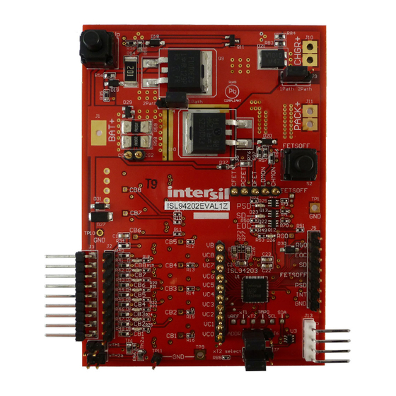
Connect the I C cable from the • Wires to connect power supply to MCB_PS_Z board ISL94202INTFACEKIT1Z board to the ISL94202EVKIT1Z board (J13). • Precision multimeter (optional) Step 9: Open the ISL94202 GUI software. Use the software to • Oscilloscope (optional) read the cell voltages. - Page 3 ISL94202EVKIT1Z FIGURE 2. ISL94202EVAL1Z TOP OF BOARD FIGURE 3. ISL94202EVAL1Z BOTTOM OF BOARD UG106 Rev.1.0 Page 3 of 35 Apr 13, 2021...
- Page 4 FETSOFF MANUAL CONTROL 6V TO 38V C PORT TO USB-I2C BOARD CELL BALANCE LEDs SET xT2 THERMISTOR TO FET OR TO CELL SET I C ADDR FIGURE 4. ISL94202EVKIT1Z BOARD SETUP UG106 Rev.1.0 Page 4 of 35 Apr 13, 2021...
- Page 5 ISL94202EVKIT1Z Quick GUI Setup Guide Step 1: Once the board is powered up and connected to the PC through the USB cable, start the GUI program. Then click on the dropdown box. FIGURE 5. MAIN GUI START-UP WINDOW UG106 Rev.1.0...
- Page 6 ISL94202EVKIT1Z Step 2: Click on “Read Voltages (Single).” This updates all the Step 4: Review the operation of the GUI features in the cell voltage, temperature and current readings, and following sections. updates the status indicators. Step 3: Click on “Read Pack Settings.” This returns the configuration parameters set in the device.
-
Page 7: Using The Gui
ISL94202EVKIT1Z Using the GUI indicators (bottom right of the screen). These indicators come directly from the device status bits. Common Screen Below the CellMIN and CellMAX readings are three boxes that show additional voltage values. The top box contains the sum of The right side of the GUI shows the status of the ISL94202. - Page 8 ISL94202EVKIT1Z changed using the GUI by clicking the “TGAIN” button in the The gain setting is important only for determining the voltage temperature box in the bottom left of the screen (below the tabs). applied at the input xTn pin.
-
Page 9: Current Readings
The default value is 1Ω, because that is the value on the ISL94202EVKIT1Z board. If the resistor value changes, then this value can be changed in the GUI (but the default cannot be changed in this revision of the GUI). - Page 10 ISL94202EVKIT1Z Above the FET control bits are some controls to change the This box also has the selection for the TGAIN bit. Clicking on the operation of the device. These controls are “PCFET enable”, TGAIN box changes the TGAIN bit in the device, updates all of the “CFET on during OV”, and “DFET on during UV”.
- Page 11 ISL94202EVKIT1Z FIGURE 20. INTERNAL MUX AND AD FORM An important first step is to select an internal Mux Channel that is going to be measured. By making a selection (clicking on a Mux selection button, see Figure 21), data collection/graphing will automatically start and after a few seconds, “Auto Range”...
- Page 12 ISL94202EVKIT1Z FIGURE 22. REGISTER 0x85 A real-time display of the register contents is displayed in Figure 23 FIGURE 23. REGISTER CONTENT Therefore, this selection programs the “MUX” blocks connected to the input of the internal AD. FIGURE 24. ANALOG MUX UG106 Rev.1.0...
- Page 13 ISL94202EVKIT1Z MAIN AD FORM TOOLS FIGURE 25. MEASUREMENT SCREEN 1. Actual Dual Byte Hex value of AD reading 19. PGA gain selected when making a current measurement 2. Calculated value based on channel selected 20. Checking will append latest collection of readings to a file 3.
- Page 14 To quit the program, click on “Quit”. FIGURE 26. INTERNAL AD UTILITY...
- Page 15 ISL94202EVKIT1Z Tab Controls As shown in Figure 27, hovering the mouse pointer over the address of a register returns a description of the register. Also, the registers are color coded to match the datasheet and to ISL94202 Memory Access group like registers. For example, in...
- Page 16 ISL94202EVKIT1Z ISL94202 ISL94202 ISL94202 MAIN SCREEN GUI RAM TAB RAM MEMORY NOTE: “Read Voltages (Single)” or “Read Status Bits” operation execution steps are numbered. “Write All RAM” writes to the ISL94202 RAM memory, then updates the Main Screen. FIGURE 28. ISL94202 GUI RAM UPDATE OPERATION (READ OPERATION NUMBERED) UG106 Rev.1.0...
-
Page 17: Configuration Memory
ISL94202EVKIT1Z CONFIGURATION MEMORY To write to individual bytes of the RAM part of the Configuration Memory, set the “RAM Access” in the Memory access box. Each The Configuration Memory consists of two parts, the EEPROM byte in RAM can be written separately. -
Page 18: User Memory
ISL94202EVKIT1Z USER MEMORY memory. The user can keep these values or load other data in the GUI boxes. To write the data to the ISL94202 User EEPROM The user memory area is different from the Configuration requires individual writes (click the “EEPROM Memory Access”... - Page 19 ISL94202EVKIT1Z PACK SETTINGS TAB The Pack Settings tab also includes a “Write EEPROM” button. This is a convenience, since it does the same function as the The Pack Settings tab (see Figure 31) provides access to the button in the EEPROM Tab. However, in the Pack Settings tab, it contents of the Configuration RAM, but with “real world”...
- Page 20 ISL94202EVKIT1Z ISL94202 GUI ISL94202 GUI ISL94202 DEVICE ISL94202 DEVICE PACK SETTINGS TAB EEPROM TAB CONFIGURATION RAM EEPROM MEMORY (EEPROM SHADOW MEMORY) (NO USER SHADOW RAM) TRANSLATE COPY COPY COPY FIGURE 32. ISL94202 GUI PACK SETTINGS TAB MEMORY OPERATIONS UG106 Rev.1.0...
-
Page 21: Voltage Limits
ISL94202EVKIT1Z VOLTAGE LIMITS CURRENT LIMITS The upper left section of the Pack Settings tab contains the To the right of the voltage settings are the current limits for voltage thresholds and delay times (see Figure 33). The voltages discharge overcurrent, charge overcurrent, and discharge can be set from 0V to 4.8V. -
Page 22: Number Of Cells
ISL94202EVKIT1Z NUMBER OF CELLS The “# of Cells” box (Figure 36) specifies the number of cells connected to the pack. The number in the box can be lower than the number of cells connected to the pack. This value is a direct representation of the number of cells, it is not the value stored in memory. -
Page 23: Power Control
ISL94202EVKIT1Z CELL BALANCE ENABLE When the TGAIN bit changes from “0” to “1” or “1” to “0”, the GUI rewrites the values of the temperature limits in the EEPROM tab Part of the Cell balance settings are the Cell Balance controls for... - Page 24 ISL94202EVKIT1Z INDIVIDUAL VOLTAGE MONITORING When measuring the current, the gain of the amplifier can be manually set prior to the ADC read by using the drop down box The GUI or an external µC can force a read of any voltage and “W”...
- Page 25 ISL94202EVKIT1Z MICROCONTROLLER DOES... µC CELL BALANCE The next set of controls (Figure 45) allows the GUI (or The GUI/µC can manually control the cell balance operation, microcontroller) to take over several functions of the device. The overriding the internal automatic balancing. Set the “µC Does most general is the “µC Does Scan”...
- Page 26 ISL94202EVKIT1Z FIGURE 48. ISL94202 GUI - DEMO TAB CURRENT DIRECTION DEMO • The device sees that there is no load and no charger, so it clears the fault condition. The “Force Charge Indicator” or “Force Discharge Indicator” controls force the device to indicate a charge or discharge •...
- Page 27 ISL94203EVAL1Z NDS7002A test purposes. 330k - Change resistor values for R83, R84 to ROHS xTH1 Therm1 Size Number Revsion reduce current. ISL94203EVAL1Z XH103F Date: Nov 12, 2013 Sheet 1 of ROHS File: ISL94203EVAL1Z Drawn by: FIGURE 51. ISL94202EVKIT1Z HARDWARE DESIGN...
-
Page 28: Bill Of Materials
ISL94202EVKIT1Z Bill of Materials REFERENCE QTY UNIT DESIGNATOR DESCRIPTION MANUFACTURER MANUFACTURER PART C13-C21 CAP, SMD, 0603, 47nF, 100V, 10%, X7R, ROHS VENKEL C0603X7R101-473KNE C2, C25, C26 CAP, SMD, 0603, 1µF, 50V, 10%, X5R, ROHS C1608X5R1H105K C1, C22, C23 CAP, SMD, 0603, 4700pF, 100V, 10%, X7R, ROHS... - Page 29 IC-MULTI-CELL, LI-ION MONITOR, 48P, QFN, 6x6, ROHS INTERSIL ISL94202IRTZ IC-TVS, ESD PROTECTOR, SMD, 6P, SOT-23-6L, 3pF, 6V, ROHS USBLC6-2SC6 MICROELECTRONICS PWB-PCB, ISL94202EVKIT1Z, REVD, ROHS CONNECTORS/HEADERS CONN-HEADER, 4PIN, 2.54mm, RIGHT-ANGLE, ROHS MOLEX 22-05-2041 CONN-HEADER, 1x9, FLAT BRK-AWAY, 2.54mm, R/A, ROHS MOLEX...
- Page 30 ISL94202EVKIT1Z Layout FIGURE 52. TOP LAYER FIGURE 53. MIDDLE LAYER 1 FIGURE 54. MIDDLE LAYER 2 FIGURE 55. BOTTOM LAYER UG106 Rev.1.0 Page 30 of 35 Apr 13, 2021...
-
Page 31: Hardware Overview
If a balance FET with lower Jumpers gate voltage requirements is desired, reduce the value of the There are three user selectable options on the ISL94202EVKIT1Z gate resistor. board. The evaluation board uses 100Ω cell balance resistors, so it ADDR balances about 40mA of current. -
Page 32: Protection Circuits
ISL94202EVKIT1Z Protection Circuits LED Indicators The board contains several protection components that should There are four LED indicators on the board. The LEDs are not be on any application. required in a real application, they are used here to provide quick monitoring of the system. - Page 33 VCELL7 VCELL6 VCELL6 VCELL6 VCELL5 VCELL5 VCELL5 VCELL4 VCELL4 VCELL4 VCELL3 VCELL3 VCELL3 VCELL2 VCELL2 VCELL2 VCELL1 VCELL1 VCELL1 VCELL0 VCELL0 VCELL0 FIGURE 57. BATTERY CONNECTION OPTIONS USING THE ISL94202EVKIT1Z BOARD UG106 Rev.1.0 Page 33 of 35 Apr 13, 2021...
- Page 34 ISL94202EVKIT1Z Errata/Q&A • Soldering the board to the PCB can change the stresses on the package from what they were during device 1. When I power the board, the device does not power up calibration. This can change the value of the voltage correctly.
-
Page 35: Revision History
ISL94202EVKIT1Z FET Gate Drive Rise/Fall Characteristics Verify basic digital logic, analog interface, level shifters, and charge pump operation. TIME (100µs/DIV) TIME (1ms/DIV) FIGURE 58. DFET RISE FIGURE 59. DFET FALL TIME (100µs/DIV) TIME (100µs/DIV) FIGURE 61. CFET FALL FIGURE 60. CFET RISE... -
Page 36: Corporate Headquarters
Renesas' products are provided only subject to Renesas' Terms and Conditions of Sale or other applicable terms agreed to in writing. No use of any Renesas resources expands or otherwise alters any applicable warranties or warranty disclaimers for these products.
Need help?
Do you have a question about the ISL94202EVKIT1Z and is the answer not in the manual?
Questions and answers